Programming Primary Phone Number using Onboard Keypad:
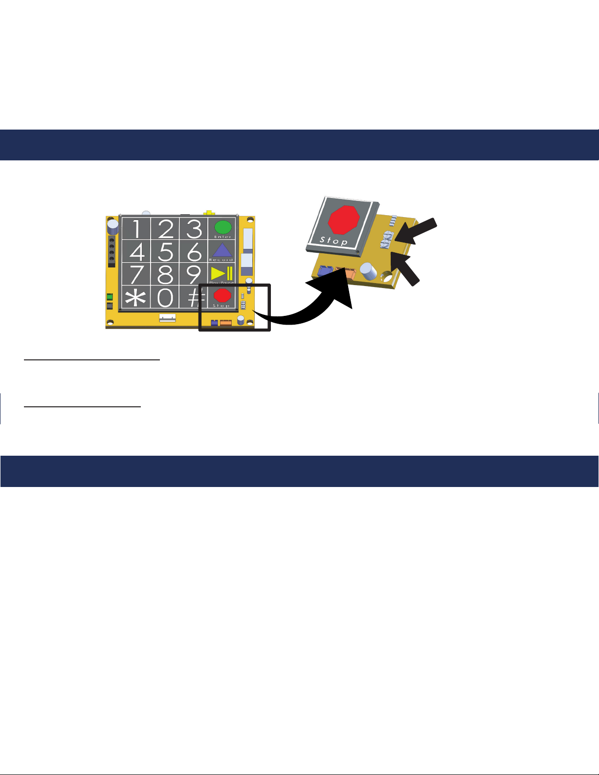
1. Press ENTER on the keypad to begin programming
2. Press 1, ENTER, the number you want the phone to dial, STOP
3. Press and hold STOP for 3 seconds
Note: In situations where a delay is needed, such as needing an 8 or 9 to dial
out, use the PLAY/PAUSE button on the keypad. The button can be pressed
multiple times for a longer delay. One PAUSE = 1 second.
Programming Secondary Phone Numbers using Onboard Keypad:
1. Press ENTER on the keypad to begin programming
2. Press 2, ENTER, the number you want the phone to dial, STOP
Note: 2100 Series VoIP Phones can call up to 5 numbers. Repeat the steps above for subsequent numbers.
Substitute 2 with 3, 4, or 5 depending on the order you want the numbers to be dialed.
Example: To dial the third number, press 3, ENTER, phone number, STOP.
3. Press and hold STOP for 3 seconds to exit programming
Programming Location Message using Onboard Keypad:
2100 Series VoIP Phones can play a location message when the call is answered. This feature is used when the
phone is calling a phone number that cannot identify where the call is coming from by caller ID or needs more
location information than the caller ID can provide. This feature is turned on by default. Perform the following steps
to program the location message feature.
Page 4
7. Enter SIP Server information into VoIP Phone
a. Click on FSX PORT tab under the menu options
on the top of the screen
b. Enter IP Address of SIP Server in Primary SIP
Server box
c. Scroll down and enter SIP Extension ID in SIP
User ID box
d. Enter Authentication ID in Authenticate ID box
(can be the same as the SIP Extension ID)
e. Enter Authentication Password in Authenticate
Password box
f. Fill in the Name locations as it will appear on the
phone
g. Click Apply at the bottom of the page
h. Scroll back down to bottom of the page and click
Reboot to restart unit and save changes
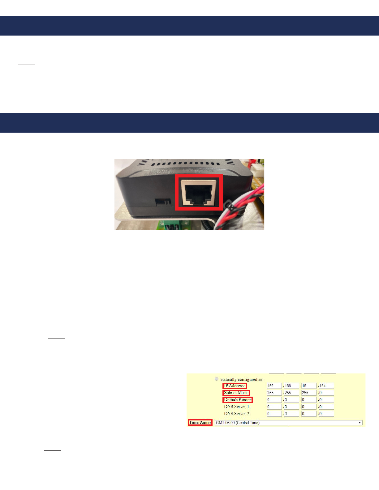
8. Change the IP address of the PC to match the new
address scheme of the VoIP Phone (follow
instructions listed in step 3).
9. Log back into the VoIP Phone in the web browser
using the new IP address of the phone
10. Verify device registration
a. In STATUS tab locate Port Status
b. Device should show Registered under
Registration
Phone Programming
Authentication
Registration
Keypad