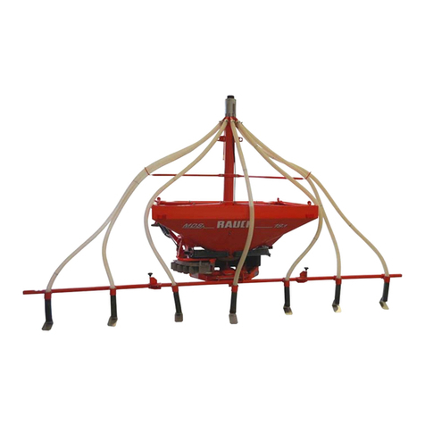
Rauch Kuhn RV 2M 1 User manual

Montageanleitung
Assembly Instruction
Notice de Montage
R
Re
ei
ih
he
en
ns
st
tr
re
eu
uv
vo
or
rr
ri
ic
ch
ht
tu
un
ng
g
R
RV
V
2
2M
M
1
1
D
Di
is
sp
po
os
si
it
ti
if
f
d
d'
'é
ép
pa
an
nd
da
ag
ge
e
s
su
ur
r
2
2
b
ba
an
nd
de
es
s
R
RV
V
2
2M
M
1
1
R
RV
V
2
2M
M
1
1
R
Ro
ow
w
S
Sp
pr
re
ea
ad
di
in
ng
g
U
Un
ni
it
t
Urządzenie do wysiewu rzędowego RV 2M 1
Vor Inbetriebnahme sorgfältig lesen! Für künftige Verwendung aufbewahren!
Diese Betriebs- Montageanleitung ist ein Teil der Maschine. Lieferanten von Neu- und Gebrauchtmaschinen sind gehalten, schriftlich zu
dokumentieren, dass die Betriebs- Montageanleitung mit der Maschine ausgeliefert und dem Kunden übergeben wurde.
A lire attentivement avant utilisation! A conserver pour toute utilisation ultérieure!
Cette notice doit être considérée comme une partie de la machine. Les fournisseurs de machines neuves ou d’occasion sont tenus de
documenter par écrit que la notice d’instructions a été fourni avec la machine au client.
Please read carefully before using the machine! Store carefully for future use!
This Operator Manual / Assembly Instruction is a part of the machine. Suppliers of new and second-hand machines are obliged to indicate
in writing that the Operator Manual / Assembly Instruction is delivered with the machine and given to the customer.
Przeczytaćdokładnie przed uruchomieniem! Zachowaćdo przyszłego użytku!
Niniejsza instrukcja obsługi i montażu stanowi integralnączęść maszyny. Dostawcy nowych i używanych maszyn zobowiązani sądo
pisemnego udokumentowania, że dostarczyli maszynęwraz z niniejsząinstrukcjąobsługi i montażu i że przekazali jąklientowi.
5900193-b-de/fr/en/pl-0311
RE0043TL B

Montageanleitung Reihenstreuvorrichtung RV 2M 1
Notice de Montage
Assembly instructions
5900193-b-de/fr/en-0311 2 R.K.
Wichtig
Sicherheitshinweise
Diese Anleitung enthält wichtige Informationen über den sicheren Betrieb und der
Funktionsweise des Zubehörs. Sie ist deshalb ein wichtiger Bestandteil Ihrer Mas-
chinenunterlagen. Vor Inbetriebnahme die Anleitung sorgfältig durchlesen und zur
künftigen Verwendung aufbewahren. Beachten Sie neben den Hinweisen in dieser
Anleitung auch alle Hinweise in der Betriebsanleitung Ihrer Maschine.
( >Kapitel: Sicherheits- und Unfallverhütungsvorschriften ; >Kapitel: Betriebs –
und Verkehrsicherheit )
Sollten Sie zu dieser Maschine noch weiteres Zubehör besitzen, so beachten Sie auch
die Hinweise in diesen Anleitungen.
Important
Consignes de sécurité
La présente notice contient les informations importantes relatives au fonctionnement
de l'équipement et à son utilisation en toute sécurité. Elle est de ce fait une compo-
sante essentielle de la documentation relative à la machine. Lire attentivement la no-
tice et la conserver soigneusement. Respecter les recommandations de la présente
notice ainsi que celles de la notice de votre machine (Consignes de sécurité pour
l'utilisation et le transport sur route)
Si vous possédez d'autres équipements, respectez également les recommandations
qui s'y rapportent.
Important
Safety notice
This operator manual contains important information concerning the safe operation and
correct use of this accessory. It is therefore considered an important addition to the
general operational information of the implement. This manual should be thoroughly
read and understood before operation commences and carefully stored for future use.
Along with the information and safety recommendations given in this manual also note
all information and safety instructions in the operator manual of your machine.
(>Section : Accident, prevention and safety issues ; >Section : Operational safety
and public road safety)
Should you have another accessory to this machine, please also note the details in this
assembly instructions.
Ważne
Wskazówki dotyczące bezpieczeństwa
Niniejsza instrukcja zawiera ważne informacje o bezpieczeństwie użytkowania i
sposobie działania wyposażenia dodatkowego. Dlatego teżjest ona ważnączęścią
składowądokumentacji Państwa maszyny. Przed uruchomieniem urządzenia starannie
przeczytaćtęinstrukcjęi przechowywaćjądo przyszłego użytku. Oprócz wskazówek
znajdujących sięw niniejszej instrukcji obsługi należy przestrzegaćwszystkich
wskazówek zawartych w instrukcji obsługi Państwa maszyny.
( >rozdział: Przepisy dotyczące bezpieczeństwa i higieny pracy ; >rozdział:
Bezpieczeństwo eksploatacji i ruchu )
Jeśli mająPaństwo jeszcze inne wyposażenie dodatkowe do tej maszyny, proszę
przestrzegaćtakże wskazówek zawartych w jego instrukcjach obsługi.
Montageanleitung
Reihenstreuvorrichtung RV 2M 1
5900193-b-de/fr/en-0311 3 R.K.
Montage der Reihenstreuvorrichtung RV 2M 1
Reihenstreuvorrichtung mit der Halterung verschrauben.
Abb. 1
Bei Streuern mit Grenzstreueinrichtung muss die Reihenstreuvorrichtung an der
"Nase des Führungsbleches" eingehängt werden (siehe Abb. 2).
Abb.2

Montageanleitung
Reihenstreuvorrichtung RV 2M 1
5900193-b-de/fr/en-0311 4 R.K.
Reihenstreuvorrichtung in der Lasche des Zugmauls mit dem Splint abstecken.
Abb. 3
Die Reihenstreuvorrichtung ist so ausgelegt, dass je eine rechts und links des
Streuers liegende Reihe (Reihenabstand: 2-5m) mit einem ca.1m breiten Streifen
bestreut wird.
Durch Verschieben der Bleche (Abb. 3; Nr. 1) kann der Reihenabstand eingestellt
werden.
Reihenabstand

Montageanleitung
Reihenstreuvorrichtung RV 2M 1
5900193-b-de/fr/en-0311 5 R.K.
Die zu bestreuende Streifenbreite kann durch Verstellen der Seitenbleche
(Abb. 5) eingestellt werden.
Abb. 5
Wegen der kleinen Streubreite dürfen die Wurfflügel nur auf die Stellung A1 - A1
eingestellt werden. Auf keinen Fall dürfen die Wurfflügel herausgezogen werden,
da sie an der Reihenstreuvorrichtung anstehen.
Nach Montage der Reihenstreuvorrichtung die Scheiben mind. einmal von Hand
durchdrehen.
Durch höheren oder tieferen Anbau des Streuers können kleine Korrekturen zwi-
schen den Abstufungen der Einstellung erzielt werden.
Die Streumenge ist von der vorhandenen Streutabelle prozentual auf die effektive
Streubreite von 2 Meter umzurechnen.
Beispiel:
Fahrgeschwindigkeit (km/h) x 2 (m) x Ausbringmenge (kg/ha) = Sollauslaufmenge (kg/min)
600
Die entsprechende Öffnungsstellung muss durch eine Abdrehprobe ermittelt werden.

Montageanleitung
Reihenstreuvorrichtung RV 2M 1
5900193-b-de/fr/en-0311 6 R.K.
Montage der Reihenstreuvorrichtung RV 2M 1 an den Geräten
MDS 732 / 932
Reihenstreuvorrichtung mit der Halterung verschrauben.
Abb. 1
Reihenstreuvorrichtung an der "Nase des Führungsbleches" einhängen (siehe
Abb. 2).
Abb.2

Montageanleitung
Reihenstreuvorrichtung RV 2M 1
5900193-b-de/fr/en-0311 7 R.K.
Reihenstreuvorrichtung in der Lasche des Zugmauls mit dem Splint abstecken.
Abb. 3
Die Reihenstreuvorrichtung ist so ausgelegt, dass je eine rechts und links des
Streuers liegende Reihe (Reihenabstand: 2-5m) mit einem ca.1m breiten Streifen
bestreut wird.
Durch Verschieben der Bleche (Abb. 3; Nr. 1) kann der Reihenabstand eingestellt
werden.
Reihenabstand

Montageanleitung
Reihenstreuvorrichtung RV 2M 1
5900193-b-de/fr/en-0311 8 R.K.
Die zu bestreuende Streifenbreite kann durch Verstellen der Seitenbleche
(Abb. 5) eingestellt werden.
Abb. 5
Wegen der kleinen Streubreite dürfen die Wurfflügel nur auf die Stellung A1 - A1
eingestellt werden. Auf keinen Fall dürfen die Wurfflügel herausgezogen werden,
da sie an der Reihenstreuvorrichtung anstehen.
Nach Montage der Reihenstreuvorrichtung die Scheiben mind. einmal von Hand
durchdrehen.
Durch höheren oder tieferen Anbau des Streuers können kleine Korrekturen zwi-
schen den Abstufungen der Einstellung erzielt werden.
Die Streumenge ist von der vorhandenen Streutabelle prozentual auf die effektive
Streubreite umzurechnen.
Beispiel:
Fahrgeschwindigkeit (km/h) x 2 (m) x Ausbringmenge (kg/ha) = Sollauslaufmenge (kg/min)
600
Die entsprechende Öffnungsstellung muss durch eine Abdrehprobe ermittelt werden.

Notice de Montage
Dispositif d'épandage sur 2 bandes RV 2M 1
5900193-b-de/fr/en-0311 9 R.K.
Montage du dispositif d'épandage sur 2 bandes RV 2M 1
Visser le dispositif d'épandage sur 2 bandes au support.
Fig. 1
Pour épandre avec le dispositif d'épandage en bordure, le dispositif d'épandage
sur 2 bandes doit être accroché à la « pointe de la tôle de guidage » (voir Fig. 2).
Fig. 2

Notice de Montage
Dispositif d'épandage sur 2 bandes RV 2M 1
5900193-b-de/fr/en-0311 10 R.K.
Fixer le dispositif d'épandage sur 2 bandes dans le timon de la chape d'attelage
avec la goupille.
Fig. 3
Le dispositif d'épandage sur 2 bandes est conçu de manière à ce qu'un rang à
droite et à gauche de l'épandeur (écart entre les rangs : 2 à 5 m) soit épandu en
bande d'environ 1 m de largeur.
En décalant les tôles (Fig. 3 ; n° 1), l'écart entre les rangs peut être réglé.
Écart entre les rangs

Notice de Montage
Dispositif d'épandage sur 2 bandes RV 2M 1
5900193-b-de/fr/en-0311 11 R.K.
La largeur de bande à épandre peut être réglée en déplaçant les
(Fig. 5) tôles latérales.
Fig. 5
En raison de la faible largeur d'épandage, les ailettes de projection doivent être
mises à la position A1 - A1 seulement. Les ailettes de projection ne doivent en
aucun cas être retirées, sachant qu'elles sont en contact avec le dispositif
d'épandage sur 2 bandes.
Après le montage du dispositif d'épandage sur 2 bandes, tourner entièrement les
disques au moins une fois à la main.
Pour apporter de petites corrections entre les niveaux de réglage, augmenter ou
réduire la hauteur d'attelage de l'épandeur.
La qualité épandue doit être convertie proportionnellement à largeur d'épandage
effective de 2 mètres à partir du tableau d'épandage existant.
Exemple :
Vitesse (km/h) x 2 (m) x dose (kg/ha) = débit théorique (kg/min)
600
Le degré d'ouverture approprié doit être déterminé à l'aide d'un contrôle de débit.

Notice de Montage
Dispositif d'épandage sur 2 bandes RV 2M 1
5900193-b-de/fr/en-0311 12 R.K.
Montage du dispositif d'épandage sur 2 bandes RV 2M 1 sur
les appareils MDS 732 / 932
Visser le dispositif d'épandage sur 2 bandes au support.
Fig. 1
Accrocher le dispositif d'épandage sur 2 bandes à la « pointe de la tôle de gui-
dage » (voir Fig. 2).
Fig. 2

Notice de Montage
Dispositif d'épandage sur 2 bandes RV 2M 1
5900193-b-de/fr/en-0311 13 R.K.
Fixer le dispositif d'épandage sur 2 bandes dans le timon de la chape d'attelage
avec la goupille.
Fig. 3
Le dispositif d'épandage sur 2 bandes est conçu de manière à ce qu'un rang à
droite et à gauche de l'épandeur (écart entre les rangs : 2 à 5 m) soit épandu en
bande d'environ 1 m de largeur.
En décalant les tôles (Fig. 3 ; n° 1), l'écart entre les rangs peut être réglé.
Écart entre les ran
g
s

Notice de Montage
Dispositif d'épandage sur 2 bandes RV 2M 1
5900193-b-de/fr/en-0311 14 R.K.
La largeur de bande à épandre peut être réglée en déplaçant les
(Fig. 5) tôles latérales.
Fig. 5
En raison de la faible largeur d'épandage, les ailettes de projection doivent être
mises à la position A1 - A1 seulement. Les ailettes de projection ne doivent en
aucun cas être retirées, sachant qu'elles sont en contact avec le dispositif
d'épandage sur 2 bandes.
Après le montage du dispositif d'épandage sur 2 bandes, tourner entièrement les
disques au moins une fois à la main.
Pour apporter de petites corrections entre les niveaux de réglage, augmenter ou
réduire la hauteur d'attelage de l'épandeur.
La qualité épandue doit être convertie proportionnellement à largeur d'épandage
effective à partir du tableau d'épandage existant.
Exemple :
Vitesse (km/h) x 2 (m) x dose (kg/ha) = débit théorique (kg/min)
600
Le degré d'ouverture approprié doit être déterminé à l'aide d'un contrôle de débit.

Assembly Instructions
RV 2M 1 Row Spreading Unit
5900193-b-de/fr/en-0311 15 R.K.
Fitting the RV 2M 1 Row Spreading Unit
Bolt the row spreading unit to its mounting bracket.
Photo 1
When spreading with the boundary spreading mechanism the row spreading unit
must be clipped over the "nose of the guide plate" (see photo 2).
Photo 2

Assembly Instructions
RV 2M 1 Row Spreading Unit
5900193-b-de/fr/en-0311 16 R.K.
Place the row spreading unit between the drawbar yoke flanges and secure with
the linchpin.
Photo 3
The row spreading unit is designed so that one row, on both the left- and right-
hand sides (row width: 2-5m), is covered with an approx. 1m wide spreading
band.
By moving the plate (Photo 3, No. 1) the row width distance can be adjusted.
Row width distance

Assembly Instructions
RV 2M 1 Row Spreading Unit
5900193-b-de/fr/en-0311 17 R.K.
The width of the spreading band can be changed by adjusting the side plate (Pho-
to 5).
Photo 5
Due to the small spreading width the disc vanes must only be set in position A1 -
A1. Under no circumstances should the disc vanes be extended, otherwise they
will foul the row spreading unit.
After fitting the row spreading unit revolve the discs by hand to make sure nothing
fouls.
Raising and lowering the unit will produce small variations in the width settings
available on the row spreading unit.
Application rates can be proportionally calculated from data in the spreading chart
to suit the effectivespreading width of 2 meters.
Example:
Driving speed (km/h) x 2 (m) x application rate (kg/ha) = nominal discharge quantity (kg/min)
600
The metering slide opening has to be determined by a calibration test.

Assembly Instructions
RV 2M 1 Row Spreading Unit
5900193-b-de/fr/en-0311 18 R.K.
Fitting the RV 2M 1 row spreading unit onto
MDS 732 / 932 models
Bolt the row spreading unit to its mounting bracket.
Photo 1
Clip the row spreading unit over the "nose of the guide plate" (see photo 2).
Photo 2

Assembly Instructions
RV 2M 1 Row Spreading Unit
5900193-b-de/fr/en-0311 19 R.K.
Place the row spreading unit between the drawbar yoke flanges and secure with
the linchpin.
Photo 3
The row spreading unit is designed so that one row, on both the left- and right-
hand sides (row width: 2-5m), is covered with an approx. 1m wide spreading
band.
By moving the plate (Photo 3, No. 1) the row width distance can be adjusted.
Row width distance

Assembly Instructions
RV 2M 1 Row Spreading Unit
5900193-b-de/fr/en-0311 20 R.K.
The width of the spreading band can be changed by adjusting the side plate (Pho-
to 5).
Photo 5
Due to the small spreading width the disc vanes must only be set in position A1 -
A1. Under no circumstances should the disc vanes be extended otherwise they
will foul the row spreading unit.
After fitting the row spreading unit revolve the discs by hand to make sure nothing
fouls.
Raising and lowering the unit will produce small variations in the width setting
available on the row spreading unit.
Application rates can be proportionally calculated from data in the spreading chart
to suit effective spreading widths.
Example:
Driving speed (km/h) x 2 (m) x application rate (kg/ha) = nominal discharge quantity (kg/min)
600
The metering slide opening has to be determined by a calibration test.
Table of contents
Languages:
Other Rauch Farm Equipment manuals

Rauch
Rauch AXENT 90.1 User manual

Rauch
Rauch MDS Series User manual

Rauch
Rauch MDS.2 Q/W User manual

Rauch
Rauch AXIS EMC ISOBUS User manual

Rauch
Rauch AERO 32.1 User manual

Rauch
Rauch RFZ 7 User manual

Rauch
Rauch Kuhn AXIS AXMAT Series User manual

Rauch
Rauch AXIS-M 30.2 User manual

Rauch
Rauch TELIMAT T 1 User manual

Rauch
Rauch MDS 8.2 User manual

Rauch
Rauch UKS 150 User manual

Rauch
Rauch QUANTRON-I User manual

Rauch
Rauch Kuhn Axis AP-Drive User manual

Rauch
Rauch AXIS-M 20.2 EMC User manual

Rauch
Rauch AXIS-H EMC Series User manual

Rauch
Rauch AERO GT 60.1 User manual

Rauch
Rauch TAXON 25.1 User manual

Rauch
Rauch AERO GT 60.1 User manual

Rauch
Rauch KUHN AP 19 User manual