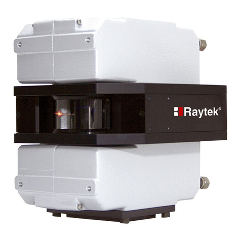
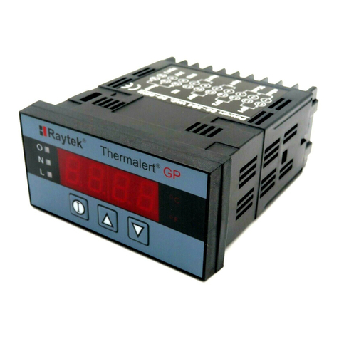
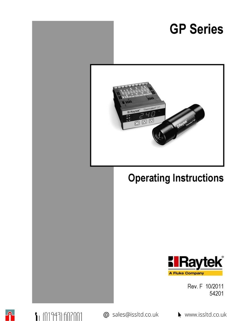
RayTek Thermalert ET Series User manual

Thermalert®
ET™Series
Operator’s Manual
Rev. J
3/96
55203-1

Thermalert ET Series Operator’s Manual Table of Contents
Table of Contents
1.0 DESCRIPTION .....................................................................................................1-1
1.1 Specifications .......................................................................................................1-3
1.1.1 Optical................................................................................................................1-3
1.1.2 Output Ranges..................................................................................................1-4
1.1.3 Operational .......................................................................................................1-5
1.1.4 Electrical ............................................................................................................1-5
1.1.5 Physical..............................................................................................................1-6
2.0 INSTALLATION...................................................................................................2-1
2.1 Preparation...........................................................................................................2-1
2.1.1 Distance and Spot Size ....................................................................................2-1
2.1.2 Ambient Temperature......................................................................................2-2
2.1.3 Atmospheric Quality .......................................................................................2-2
2.1.4 Electrical Interference......................................................................................2-2
2.1.5 Wiring................................................................................................................2-3
2.1.6 Multiple Sensors...............................................................................................2-3
2.2 Mechanical Installation ......................................................................................2-4
2.2.1 Sensor (standard) .............................................................................................2-4
2.2.2 Sensor (Air/Water-Cooled Housing)............................................................2-5
2.2.3 Air Purge Collar ...............................................................................................2-5
2.2.4 ThermoJacket....................................................................................................2-6
2.2.5 Right Angle Mirror ..........................................................................................2-7
2.2.6 Sighting Viewer Tool........................................................................................2-7
2.3 Electrical Installation ..........................................................................................2-8
2.3.1 Thermocouple Output Models.......................................................................2-9
2.3.2 Current Output Models.................................................................................2-10
3.0 OPERATION..........................................................................................................3-1
3.1 Theory of Operation ...........................................................................................3-1
3.2 Controls ................................................................................................................3-2
3.2.1 Temperature Range..........................................................................................3-3
3.2.2 Emissivity Setting.............................................................................................3-4
3.2.3 Peak Hold..........................................................................................................3-4
3.2.4 Averaging Filter................................................................................................3-4

Table of Contents Thermalert ET Series Operator’s Manual
4.0 MAINTENANCE..................................................................................................4-1
4.1 Troubleshooting Minor Problems.....................................................................4-1
4.2 Fail-safe Operation..............................................................................................4-1
4.3 Cleaning the Lens................................................................................................4-2
4.4 Customer Service.................................................................................................4-2
APPENDIX A: OBJECT EMISSIVITY..........................................................................A-1
How to Determine Object Emissivity.............................................................................A-1
Typical Emissivity Values ................................................................................................A-1
APPENDIX B: CE CONFORMITY FOR THE EUROPEAN COMMUNITY..........B-1
GLOSSARY OF TERMS

TWO YEAR LIMITED WARRANTY
Raytek warrants this product to be free from defects in material and workmanship under normal use and
service for a period of two years from date of purchase except as hereinafter provided. This warranty
extends only to the original purchaser (a purchase from Raytek or Raytek’s licensed distributors is an origi-
nal purchase). This warranty shall not apply to fuses or batteries. Factory calibration is warranted for a
period of one year. The warranty shall not apply to any product which has been subject to misuse, neglect,
accident, or abnormal conditions of operation or storage. Should Raytek be unable to repair or replace the
product within a reasonable amount of time, purchaser’s exclusive remedy shall be a refund of the purchase
price upon return of the product.
In the event of failure of a product covered by this warranty, Raytek will repair the instrument when it is
returned by the purchaser, freight prepaid, to an authorized Service Facility within the applicable warranty
period, provided Raytek’s examination discloses to its satisfaction that the product was defective. Raytek
may, at its option, replace the product in lieu of repair. With regard to any covered product returned within
the applicable warranty period, repairs or replacement will be made without charge and with return freight
paid by Raytek, unless the failure was caused by misuse, neglect, accident, or abnormal conditions of opera-
tion or storage, in which case repairs will be billed at a reasonable cost. In such a case, an estimate will be
submitted before work is started, if requested.
THE FOREGOING WARRANTY IS IN LIEU OF ALL OTHER WARRANTIES, EXPRESSED OR IMPLIED,
INCLUDING BUT NOT LIMITED TO ANY IMPLIED WARRANTY OF MERCHANTABILITY, FITNESS,
OR ADEQUACY FOR ANY PARTICULAR PURPOSE OR USE. RAYTEK SHALL NOT BE LIABLE FOR
ANY SPECIAL, INCIDENTAL OR CONSEQUENTIAL DAMAGES, WHETHER IN CONTRACT, TORT,
OR OTHERWISE.
WORLDWIDE
Raytek, Inc.
Billing: Box 1820, Santa Cruz, CA 95061-1820
Shipping: 1201 Shaffer Road, Santa Cruz, CA 95060
Phone: (408) 458-1110 (800) 227-8074 FAX: (408) 458-1239
EUROPE
Raytek GmbH
Arkonastrasse 45-49, D-13189 Berlin, Germany
Phone: 030/47 80 08-42 030/47 80 08-0 FAX: 030/47 10 25-1
JAPAN
Raytek Japan, Inc.
Sumitomo Marine Bldg., 2-27-15, Hon-Komagome, Bunkyo-ku, Tokyo 113, Japan
Phone: 03-5976-1531 FAX: 03-5976-1530
CHINA
Raytek China Company
Zhong Fa Investment Bldg., Ste. 221, 12 Jiu Xian Qiao Road, Chao Yang District, Beijing 100016 China
Phone: 86-10/6437-0284 FAX: 86-10/6437-0285
GREAT BRITAIN
Raytek UK Ltd.
P.O. Box 120, Milton Keynes, Buckinghamshire, MK1 1ZU, United Kingdom
Phone: 441-908/630800 FAX: 441-908/630900
BRASIL
Raytek do Brasil
Subsidiária da Raytek, Inc.
R. Francisco Paula Aquino, 13, Sorocaba – SP – Brasil CEP 18013 - 200
Phone: (0152) 27,6556 FAX: (0152) 27,1091
Raytek and Thermalert are registered trademarks and 3 is a trademark of Raytek Corporation
© Raytek Corporation 1996

Thermalert ET Series Operator’s Manual 1-1
1.0 DESCRIPTION
The Thermalert®ET™series of instruments are noncontact infrared temperature mea-
surement systems. They are energy transducers designed to measure accurately and
repeatedly the amount of heat energy emitted from an object and to convert that ener-
gy into a measurable electrical signal.
Each model operates as an integrated temperature measurement subsystem consist-
ing of optical elements, spectral filters, integrated detector, digital electronics and a
NEMA-4 (IEC 529, IP 65) housing. They are built to operate on a 100 percent duty
cycle in industrial environments. Outputs consist of standardized thermocouple or
current signals commonly available for use with controllers, recorders, alarms or A/D
interfaces.
Table 1-1: Models
Note: When reviewing this manual, inquire of possible exceptions resulting from customized
features. Check with your sales representative whenever a parameter is critical or oper-
ation seems abnormal.

1-2 Thermalert ET Series Operator’s Manual
Accessories and Options
A full range of accessories and options for mounting and operating in particularly
harsh environments are available.
Air/water cooled housing 15m, 30m, 60m (50’, 100’, 200’) cable
Sighting Viewer ThermoJacket
Right Angle Mirror – Mounting Flange
Air Purge Collar – Mounting Bracket
Mounting Nut – Sighting Tube Mounting Flange
Fixed Bracket – Sighting Tube, 305mm (12 in)
Adjustable Bracket – Ceramic Sighting Tube, 305mm (12in)
Swivel Bracket – Adjustable Pipe Adapter Accessory
110/220 to 12 VAC power supply – Blast Gate Accessory
Figure 1-1: Accessories and Options

Thermalert ET Series Operator’s Manual 1-3
1.1 SPECIFICATIONS
1.1.1 Optical
Nominal optical resolution values are stated at minimum 90% energy. Distance to
size (D:S) ratios represent nominal values.
2LT, 3LT
Standard Focus 2LT, 3LT
Close Focus
2P7, 3P7
Standard Focus 2HT, 3HT
Standard Focus
2HT, 3HT
Close Focus 2G5, 3G5
Standard Focus

1-4 Thermalert ET Series Operator’s Manual
1.1.2 Output Ranges
Measurement Range
Thermocouple Output 2LT -18 to 760°C (0 to 1400°F), Type J
0 to 870°C (32 to 1600°F), Type K
2P7 10 to 360°C (50 to 650°F), Type J
2G5 260 to 1650°C (500 to 3000°F), Type R
2HT 500 to 1700°C (1000 to 3000°F), Type R
Current Output (switch selectable)
3LT Range Setting °F Version °C Version
10 to 200 0 to 100
2 0 to 400 0 to 200
3 0 to 800 0 to 400
4 0 to 1400 0 to 800
3P7 Range Setting °F Version °C Version
150 to 350 10 to 110
2 50 to 650 10 to 360
3G5 Range Setting °F Version °C Version
1500 to 1500 260 to 815
2 500 to 3000 260 to 1650
3HT Range Setting °F Version °C Version
11000 to 2000 500 to 1000
2 1000 to 3000 500 to 1700
Spectral Response LT Versions 8 to 14 microns
P7 Versions 7.9 microns (nominal)
G5 Versions 5.0 microns (nominal)
HT Versions 2.2 microns (nominal)
Accuracy ± 1% of reading or 1.4°C (2.5°F) @ 25°C (77°F)
whichever is greater
Repeatability ± 0.5% of Reading, ± 1 digit °C or °F

Thermalert ET Series Operator’s Manual 1-5
1.1.3 Operational
Response Time • 300 msec, 100 msec option (95% response)
• 80 msec is standard on HT (2.2µm) versions
Emissivity • 0.10 to 0.99, in 0.01 increments
Peak Hold • 0.1 sec decay time to 50% of peak value
(with no peak hold)
• 14°C (25°F) per second (nominal decay rate)
(with maximum peak hold)
Averaging • 0.3 sec response time (with no averaging)
• 5 sec response time (with maximum averaging)
Fail Safe • Full scale (20.3 mA) when under or over
range or subrange
1.1.4 Electrical
Power 12 VAC nominal (10.5 to 16 VAC), 100 mA, 50 to 60 Hz
Outputs Thermocouple Versions
2LT Type J or K
2P7 Type J
2G5 Type R
2HT Type R
Current Versions
• all ranges: 4-20 mA
• under or over specified
operating temperature
ranges: 20 mA
• loop impedance, Max: 300 ohms
Interconnection 5-pin DIN connector, 4.5 m (15 ft.) cable standard

1-6 Thermalert ET Series Operator’s Manual
1.1.5 Physical
Environmental Rating NEMA 4, (IEC 529, IP 65)
Rated with conduit and compression fitting
(which prevents liquid from entering through
the connector)
Ambient Operating Temp 0 to 50°C (32 to 120°F)
• with air cooling 0 to 120°C (32 to 250°F)
• with water cooling 0 to 175°C (32 to 350°F)
• with ThermoJacket 0 to 315°C (32 to 600°F)
Storage Temperature -40 to 65°C (-40 to 150°F)
Environmental Rating NEMA-4 (IEC 529, IP 65) with conduit and
compression fitting
Vibration MIL STD 810D (IEC 68-2-6)
3G’s, any axis, 11 to 200 Hz
Shock MIL STD 810D (IEC 68-2-27)
50G’s, 11 mSec, any axis
Dimensions
• Length Standard: 178.3mm (7.02 in)
Water-cooled housing: 178.3mm (7.02 in)
• Diameter Standard: 56.8mm (2.24 in)
Water-cooled housing: 75.7mm (2.98 in)
• Weight Standard: 500 g (1.2 lbs)
Water-cooled housing: 800 g (1.7 lbs)

Thermalert ET Series Operator's Manual 2-1
2.0 INSTALLATION
The installation process consists of the following:
• Preparation
• Mechanical Installation
• Electrical Installation
The most important part in the installation process is preparation. Please read Section
2.1, Preparation, thoroughly before proceeding with the mechanical and electrical
installation sections.
2.1 PREPARATION
Sensor location and configuration depends on the application. Before deciding on a
location, you need to be aware of the ambient temperature of the location, the atmos-
pheric quality of the location, and the possible electromagnetic interference in that
location. You need to be aware of the spot size on your target and how far away the
sensor needs to be mounted. Also, if you plan to use air purging and/or air or water
cooling, you need to have air and water connections available. The following subsec-
tions cover topics to consider before you install the sensor.
2.1.1 Sensor Location
The desired spot size to be measured on the target will determine the maximum
working distance and appropriate focus model. The target spot size must contain the
entire field of view of the sensor (Figure 2-1). It must be the same as or smaller than
the desired spot size.
Figure 2-1: Sensor Placement

2-2 Thermalert ET Series Operator's Manual
Proper sensor placement is important for accurate temperature measurements. The
sensor must have a clear view of the target. There can be no obstructions, either on
the lens, window, or in the atmosphere. Do not mount the sensor at angles greater
than 45° from the target.
2.1.2 Ambient Temperature
The sensor is designed to operate in ambient temperatures between 0°C (32°F) and
50°C (120°F). In ambient conditions above 50°C (120°F), an air/water-cooled housing
option is available, which extends the operating range to 120°C (250°F), with air cool-
ing, and 175°C (350°F), with water cooling. When using water cooling, it is strongly
recommended to also use the air purge collar to avoid condensation on the lens. Also
available is a ThermoJacket accessory, which allows use of the sensing head in ambi-
ent temperatures up to 315°C (600°F).
2.1.3 Atmospheric Quality
It is important to maintain cleanliness of the lens at all times to prevent erroneous
readings and damage to the lens. An air purge collar is available and recommended
to protect the lens from smoke, fumes, dust, and other contaminants.
2.1.4 Electrical Interference
To minimize electrical or electromagnetic interference or "noise," follow these precau-
tions:
• Mount the sensor as far away as possible from potential sources of electrical
interference (e.g., motorized equipment that produce large step load changes).
• Make sure the shield wire in the sensor cable is earth grounded.
• For additional protection, use conduit for the AC power lines and for any
external connections. Note that solid conduit is better than flexible conduit in
high noise environments.
• Do not run AC power for other equipment in the same conduit.

Thermalert ET Series Operator's Manual 2-3
2.1.5 Wiring
Sensor power will connect to 12 VAC, which should be as “noise free” as possible. Do
not ground the secondary of the transformer.
CAUTION
When routing the interface cable, avoid paths running near sources of
interference such as large electric motors, welders and generators.
Note that when using thermocouple output models, be sure to use the appropriate
thermocouple wire.
2.1.6 Multiple Sensors
There are two types of interfacing to consider when connecting more than one sensor
to a controller (or other device): differential and single-ended. Differential configura-
tions are preferred over single-ended since they are less susceptible to noise. This
advantage, of course, must be weighed against the disadvantage of using additional
input positions. See Figure 2-2 for thermocouple outputs; the longer the cable, the
more likely differential hook-ups should be used.
Figure 2-2: Multiple Sensors

2-4 Thermalert ET Series Operator's Manual
2.2 MECHANICAL INSTALLATION
Use the following as a reference for installing the sensors and accessories, as well as
the air and water connections.
2.2.1 Sensor (standard)
All sensors are supplied with a fixed bracket and mounting nut. Alternatively, the
sensor may be mounted through a hole or may be mounted using a customer-sup-
plied bracket or other accessories. See Section 1.0 for a description of accessories and
options for the sensor.
Figure 2-3: Sensing Head
Figure 2-4: Fixed Mounting Bracket
Figure 2-5: Adjustable Mounting Bracket

2.2.2 Sensor (Air/Water-Cooled Housing)
The Air/Water-Cooled Housing option allows the sensor to be used in ambient tem-
peratures up to 120°C (250°F) for air-cooled, and 175°C (350°F) for water-cooled. It is
supplied with two 3.2 mm (1/8”) NPT brass fittings. Air flow should be 0.1 to 1.5
cmm (3 to 5 cfm). Water flow should be approximately 2 liters (0.5 gallons) per
minute, and water temperature should be 10 to 27°C (50 to 80°F) for efficient cooling.
Chilled water below 10°C (50°F) is not recommended. To avoid condensation and
lens damage, use of the Air Purge Collar with the Water-Cooled Housing is required.
Thermalert ET Series Operator's Manual 2-5
Figure 2-6: Sensing Head with Air/Water-Cooled Housing
Figure 2-7: Air Purge Collar
2.2.3 Air Purge Collar
The Air Purge Collar accessory is used to keep dust, moisture, airborne particles, and
vapors away from the lens. It may be installed before or after the bracket (see acces-
sories drawing in Section 1.0) and screwed in fully. Air flows into the 3.2 mm (1/8”)
NPT brass fitting and out the front aperture. Air flow should be a maximum of 0.5 to
1.5 liters/sec (1 to 3 cfm). Clean or “instrument” air is recommended to avoid conta-
minants from settling on the lens.

2-6 Thermalert ET Series Operator's Manual
2.2.4 ThermoJacket
The ThermoJacket accessory allows use of sensing heads in ambient temperatures up
to 315°C (600°F). The ThermoJacket’s rugged cast aluminum housing completely
encloses the head and provides water cooling and air purging in one unit. Sensing
heads can be easily installed or removed from the mounted ThermoJacket housing.
Figure 2-8: ThermoJacket and Accessories

Thermalert ET Series Operator's Manual 2-7
2.2.5 Right Angle Mirror
The Right Angle Mirror is used to get a perpendicular view of a target when space is
limited or when you need to avoid excessive radiation to the sensor. It must be
installed after the bracket or after the Air Purge Collar, if used, and screwed in fully.
In dusty or contaminated environments, connect air to the mirror’s nipple to keep the
first surface mirror clean. If used in conjunction with the Air Purge Collar, both the
Right Angle Mirror and the Air Purge Collar must be air purged.
Figure 2-9: Right Angle Mirror
IMPORTANT
When using the Right Angle Mirror, adjust emissivity settings downward by 5%
(e.g., for an object with an emissivity of 0.95, use 0.90; for an object with 0.80 use
0.76; for 0.65 use 0.62. This corrects for infrared energy losses due to the mirror.
2.2.6 Sighting Viewer Tool
The Sighting Viewer Tool accessory is used to aid in the alignment of the sensor. It is
often used when the object is small and far from the sensor as well as in situations
when obtaining a direct in-line sighting is difficult. It can be used both with and
without the Air Purge Collar but not with the Right Angle Mirror. For best results,
first secure the sensor to the bracket using the mounting nut or Air Purge Collar and
then screw on the Sighting Viewer Tool fully. Next, position and secure the bracket,
being sure to remove the Sighting Viewer Tool when alignment is complete.
Figure 2-10: Sighting Viewer Tool

2-8 Thermalert ET Series Operator's Manual
2.3 ELECTRICAL INSTALLATION
A standard 4.5 m (15 ft.) cable is supplied with each sensor. It consists of a factory-
installed 5-pin DIN connector on one end and four leads plus shield on the other end.
Note: Thermocouple and current output models have different cables. It is important to use
the appropriate cables to maintain accuracy.
When using protective conduit, consider the following:
• Use a double-hex water tight compression coupling designed for 19 mm (3/4
inch) EMT thin walled conduit.
•To avoid undue stress on the housing during installation, attach the coupling
first to the conduit and then to the sensor. Do NOT suspend the conduit from
the sensor, or the sensor from the conduit.
When powered by a transformer, the unit may be susceptible to line noise. Line noise
can be eliminated by the addition of capacitors on the secondary of the stepdown
transformer. Note that any stepdown transformer shipped with the unit includes the
necessary capacitors. Customer supplied transformers will require the modifications
shown in the following illustration.
Note: Use 0.01µF/250 VAC capacitors for C1 and C2. An example is Sprague p/n125LS10
Ceramic Disk Capacitor.
Figure 2-11: Stepdown Transformer Modifications

Thermalert ET Series Operator's Manual 2-9
2.3.1 Thermocouple Output Models
These sensors provide simulated thermocouple outputs. They are calibrated thermo-
couple equivalent signals that may be interfaced to any controller, data logger, indica-
tor, computer I/O, etc., requiring a specific type of thermocouple input.
Electrical Connections
Color Connector Pin Function
Brown 1 12 VAC supply
Brown 2 12 VAC supply
Red 3 (-) Thermocouple
output
White, Yellow,
Black 4 (+) Thermocouple
output, J, K, R-type
Uninsulated None Cable shield to earth
ground
CAUTION
Always use thermocouple wire on pins 3 and 4. Note that Red is
minus. For all color coding of thermocouples, ANSI standards are
used; these standards vary considerably by country.
Installation Checklist
1. The “power on” LED should be lit when power is supplied.
2. The Average and Peak Hold controls should be turned fully counter-clockwise.
3. Connect a thermocouple meter to the output: white, yellow or black (+), red (-).
Make sure the emissivity is less than 1.00.
4. Aim the sensor at objects with different temperatures. The thermocouple meter
will respond to changes.

2-10 Thermalert ET Series Operator's Manual
Electrical Connections
Color Connector Pin Function
Red 1 12 VAC supply
Black 2 12 VAC supply
Green 3 (-) 4-20 mA output
White 4 (+) 4-20 mA output
Uninsulated None Cable shield to earth
ground
2.3.2 Current Output Models
These sensors provide a 4-20 milliamp linear current output. These calibrated signals
may be interfaced to any controller, data logger, indicator, computer I/O, etc., requir-
ing a 4-20 mA linear current input. Note that four (4) wires are required: two (2) for
the calibrated linear signal and two (2) for the power supply.
Installation Checklist
1. The “power on” LED should be lit when power is supplied.
2. The Average and Peak Hold controls should be turned fully counter-clockwise.
3. Set a digital voltmeter to measure at least 20 mA and connect it to the output
(white [+], green [-]), and make sure the emissivity is less than 1.00.
4. Aim the sensor at objects with different temperatures. The meter will respond to
these changes.
This manual suits for next models
8
Table of contents
Other RayTek Measuring Instrument manuals
Popular Measuring Instrument manuals by other brands

Novalynx
Novalynx 110-WS-16RC instruction manual

Mountz
Mountz TorqueMate Plus Operation manual

Renishaw
Renishaw SFP1 Installation and user guide

Louroe Electronics
Louroe Electronics ASK-4 Installation and operating instructions

Thommen
Thommen CM20 Installation and operating manual

Bushnell
Bushnell NEO GHOST user manual