manuals.online logo
Brands
  1. Home
  2. •
  3. Brands
  4. •
  5. Siemens
  6. •
  7. Measuring Instrument
  8. •
  9. Siemens 7LQ3 353 User manual

Siemens 7LQ3 353 User manual

1
Measuring current transformer
Intended use
Measuring current transformers 7LQ3 353 are preferably used for
the monitoring of power supply in medically used areas. There
they measure the load current and convert it into a signal usable
for evaluating devices.
Safety information
Installation, connection and commissioning of electrical equip-
ment shall only be carried out by qualified electricians:
Particular attention shall be paid to:
●the current safety regulations and
●the general safety instructions for SIEMENS products.
Function
Measuring current transformers 7LQ3 353 measure the load cur-
rent of a phase for the supply of medically used areas.
Evaluating devices for 7LQ3 353 are for example insulation moni-
toring devices 7LQ3 350.
Installation and connection
Installation
The measuring current transformers is intended for screw fixing.
Install the measuring current transformer by means of screws M3
to a suitable place. Avoid an installation in the proximity of strong
magnetic fields.
For the measuring current transformer 7LQ3 353 alternatively
also DIN rail mounting acc. to IEC 60715 is possible. :
1. Install first the associated mounting angle to the adapter
for DIN rail.
2. Screw then the measuring current transformer 7LQ3 353
to the mounting angle.
3. Mount the adapter on the DIN rail.
Consider also the manual or the instruction leaflet of the evalua-
ting device (e.g. instruction leaflet 7LQ3 350).
Prior to installation and before work activities are
carried out on the connecting cables, make sure that
the mains power is disconnected.
Failure to comply with this safety information may
cause electric shock to personnel.
Furthermore, substantial damage to the electrical in-
stallation and destruction of the device might occur.
Messstromwandler
Bestimmungsgemäße Verwendung
Messstromwandler 7LQ3 353 werden vorzugsweise zur Überwa-
chung der Spannungsversorgung in medizinisch genutzten Räu-
men eingesetzt. Dort erfassen sie den Laststrom und setzen ihn in
ein für auswertende Geräte nutzbares Signal um.
Sicherheitshinweise allgemein
Montage, Anschluss und Inbetriebnahme nur durch Elektrofach-
kraft!
Beachten Sie unbedingt:
●die bestehenden Sicherheitsvorschriften und
●die allgemeinen sicherheitstechnischen Hinweise für SIE-
MENS-Produkte.
Funktionsbeschreibung
Messstromwandler 7LQ3 353 überwachen den Laststrom einer
Phase zur Speisung von medizinisch genutzten Räumen.
Auswertende Geräte für 7LQ3 353 sind beispielsweise Isolations-
wächter 7LQ3 350.
Montage und Anschluss
Montage
Der Messstromwandler ist zur Schraubbefestigung vorgesehen.
Montieren Sie den Messstromwandler mittels Schrauben M3 an
einen geeigneten Ort. Vermeiden Sie eine Montage in der Nähe
von starken Magnetfeldern.
Für den Messstromwandler 7LQ3 353 besteht wahlweise auch
die Möglichkeit zur Befestigung auf Hutschiene:
1. Montieren Sie zuerst den zugehörigen Montagewinkel an
den Rastfuß.
2. Schrauben Sie dann den Messstromwandler 7LQ3 353 an
den Montagewinkel.
3. Klemmen Sie den Rastfuß auf die Hutschiene.
Beachten Sie auch das Handbuch oder den Beipackzettel des aus-
wertenden Gerätes (z.B. Beipack 7LQ3 350).
Stellen Sie vor Einbau des Gerätes und vor Arbeiten
an den Anschlüssen des Gerätes sicher, dass die An-
lage spannungsfrei ist.
Wird dies nicht beachtet, so besteht für das Personal
die Gefahr eines elektrischen Schlages.
Außerdem drohen Sachschäden an der elektrischen
Anlage und die Zerstörung des Gerätes.
7LQ3 353
2514304108a (K210004) / 10.2004
Deutsch English
22514304108a (K210004) / 10.2004
7LQ3 353
Dimension diagram
Figure 1: Way of mounting 1 (all dimensions in mm)
Figure 2: Way of mounting 2 (all dimensions in mm)
A adapter for DIN rail
Bmountingangle
C Sheet metal screw 3x8
D Cylinder head screw M3x6
E Connecting plug
Connection
1. Install the measuring current transformer by connecting
the two wires to the evaluating device under considera-
tion of information in the instruction leaflet of the evalua-
ting device and the technical data (in particular the cable
lengths) in this instruction leaflet.
2. Short-circuit the transformers which are not being used by
connecting the contacts S1 (k) and S2 (l) to PE.
3. Pass the conductors to be monitored at a right angle
through the measuring current transformer.
Maßbild
Abb. 1: Montagevariante 1 (alle Maße in mm)
Abb. 2: Montagevariante 2 (alle Maße in mm)
A Rastfuß
BMontagewinkel
CBlechschraube3x8
D Zylinderschraube M3x6
E Anschlussstecker
Anschluss
1. Schließen Sie den Messstromwandler mit zwei Anschluss-
drähten an das auswertende Gerät an. Beachten Sie dabei
die Angaben in dem Beipackzettel des auswertenden
Gerätes und die technischen Daten (insbesondere die Lei-
tungslängen) dieses Beipackzettels.
2. Schließen Sie nicht benutzte Messstromwandler kurz. Ver-
binden Sie dazu die Kontakte S1 (k) und S2 (l) mit PE.
3. Führen Sie den zu überwachenden Leiter möglichst sym-
metrisch und rechtwinklig durch den Messstromwandler.
7LQ3 353
B
C
A
20.2
33.1
38
13
38.0
58.0
64.0
D
E
P1(K)
S2 (l)
S1(k)
74,7
69.5
74.7
7LQ3 353
B
C
A
D
E
P1 (K)
S1 (k)
S2 (l)
3
2514304108a (K210004) / 10.2004
7LQ3 353
Cable routing through the measuring current transformer
Figure 3: Cable routing
P1 (K) from power supply
P2 (L) to the load
S1 (k), S2 (l) Connections of measuring current transformer
Commissioning
Prior to commissioning, check proper connection of the transfor-
mer
Standards
DIN EN 60044-1:2001-11
Measuring current transformers - Part 1: Current transformers
(IEC 60044-1:1999 + A1:2000); German version DIN EN 60044-
1:2001-11
Technical data
Insulation coordination acc. to IEC 60664-1
Rated voltage UmAC 720 V
Rated impulse voltage Uisol 2,5 kV
Measuring circuit
Rated transformation ratio kn50/0.05 A
Rated burden 65 Ω
Max. rated primary current 50 A
Min. rated primary current 0.5 A
Nominal power 2 VA
Nominal frequency 50 ... 400 Hz
Internal resistance 23 Ω
Accuracy class 1
Rated continuous thermal current 60 A
Rated short-time thermal current (1 s) 300 A
Dynamic rated current (30 s) 600 A
General data
Standard IEC60044-1
Shock resistance acc. to IEC 60068-2-27 (built-in) 15 g / 11 ms
Bumping IEC60068-2-29 (during transport) 40 g / 6 ms
Vibration resistance IEC 60068-2-6 (built-in) 1 g / 10 ... 150 Hz
Vibration resistance IEC 60068-2-6 (Device out of service) 2g / 10 ... 150 Hz
Consider the current indication of the evaluating
devices.
Mögliche Leitungsführung durch den Messstromwandler
Abb. 3: Leitungsführung
P1 (K) von Spannungsversorgung
P2 (L) zur Last
S1 (k), S2 (l) Messstromwandler-Anschlüsse
Inbetriebnahme
Kontrollieren Sie vor der Inbetriebnahme den ordnungsgemäßen
Anschluss des Messstromwandlers.
Normen
DIN EN 60044-1:2001-11
Messwandler - Teil 1: Stromwandler (IEC 60044-1:1999 +
A1:2000); Deutsche Fassung DIN EN 60044-1:2001-11
Technische Daten
Isolationskoordination nach IEC 60044-1
Bemessungsspannung UmAC 720 V
Bemessungs-Stoßspannung Uisol 2,5 kV
Messkreis
Nennübersetzungsverhältnis kn50/0,05 A
Nennbürde 65 Ω
Primärnennstrom max 50 A
Primärnennstrom min. 0,5 A
Nennleistung 2 VA
Nennfrequenz 50 ... 400 Hz
Innenwiderstand 23 Ω
Genauigkeitsklasse 1
Thermischer Bemessungs Dauerstrom 60 A
Thermischer Bemessungs Kurzzeitstrom (1 s) 300 A
Dynamischer Bemessungsstrom (30 s) 600 A
Allgemeine Daten
Norm IEC60044-1
Schockfestigkeit IEC60068-2-27 (Eingebaut) 15 g / 11 ms
Dauerschocken IEC60068-2-29 (Transport) 40 g / 6 ms
Schwingungsbeanspruchung IEC 60068-2-6 (Eingebaut) 1 g / 10 ... 150 Hz
Schwingungsbeanspruchung IEC 60068-2-6 (Gerät außer Betrieb) 2g / 10 ... 150 Hz
Beachten Sie die Stromanzeige der auswertenden
Geräte.
S1 (k)
S2 (l)
P2 (L)P1 (K)
42514304108a (K210004) / 10.2004
7LQ3 353
SIEMENS AG • Electrical Installation Technology Tel.: +49 (0)941 790-01 E-Mail: [email protected]
Siemensstraße 10 • 93055 Regensburg Support Web: http://www.siemens.de/installationstechnik
Postfach 100953 • 93009 Regensburg Tel.: +49 (0)180-5050-222
Fax: +49 (0)180-5050-223
Alle Rechte vorbehalten.
Nachdruck und Vervielfältigung
nur mit Genehmigung des Herausgebers.
Technische Änderungen vorbehalten!
All rights reserved.
Reprinting and duplicating
only by permission of publisher.
Right to technical modifications reserved!
©2004 SIEMENS Germany
Ambient temperature, during operation 0 °C ... +85 °C
Ambient temperature, during storage -40 °C ... +85 °C
Climatic category acc. to DIN IEC60721-3-3 3K5
Operating mode continuous operation
Position any position
Connection Faston plug 6.3 x 0.8 mm
Type of connection to the measuring current transformer
Single wires ≥ 0.75 mm2up to 1 m
Single wires, twisted ≥ 0.75 mm2up to 10 m
Screened cable ≥ 0.6 mm2 (single-ended connection to PE) e.g. JY(ST)Y 2 x 0.6 up to 40 m
Screw mounting M3
Flammability class UL94V-0
Ordering details
Umgebungstemperatur, bei Betrieb 0 °C ... +85 °C
Umgebungstemperatur, bei Lagerung -40 °C ... +85 °C
Klimaklasse nach DIN IEC60721-3-3 3K5
Betriebsart Dauerbetrieb
Einbaulage beliebig
Anschlussart Fastonstecker 6,3 x 0,8 mm
Anschlussleitung zum Messstromwandler
Einzeldrähte ≥0,75 mm² bis 1 m
Einzeldrähte verdrillt ≥0,75 mm² bis 10 m
Schirmleitung ≥0,6 mm² (Schirm einseitig an PE) z.B. JY(ST)Y 2 x 0,6 bis 40 m
Schraubbefestigung M3
Entflammbarkeitsklasse UL94V-0
Bestellangaben
Typ /Type
Innendurchmesser
Internal diameter
(mm)
7LQ3 353 13

Other Siemens Measuring Instrument manuals

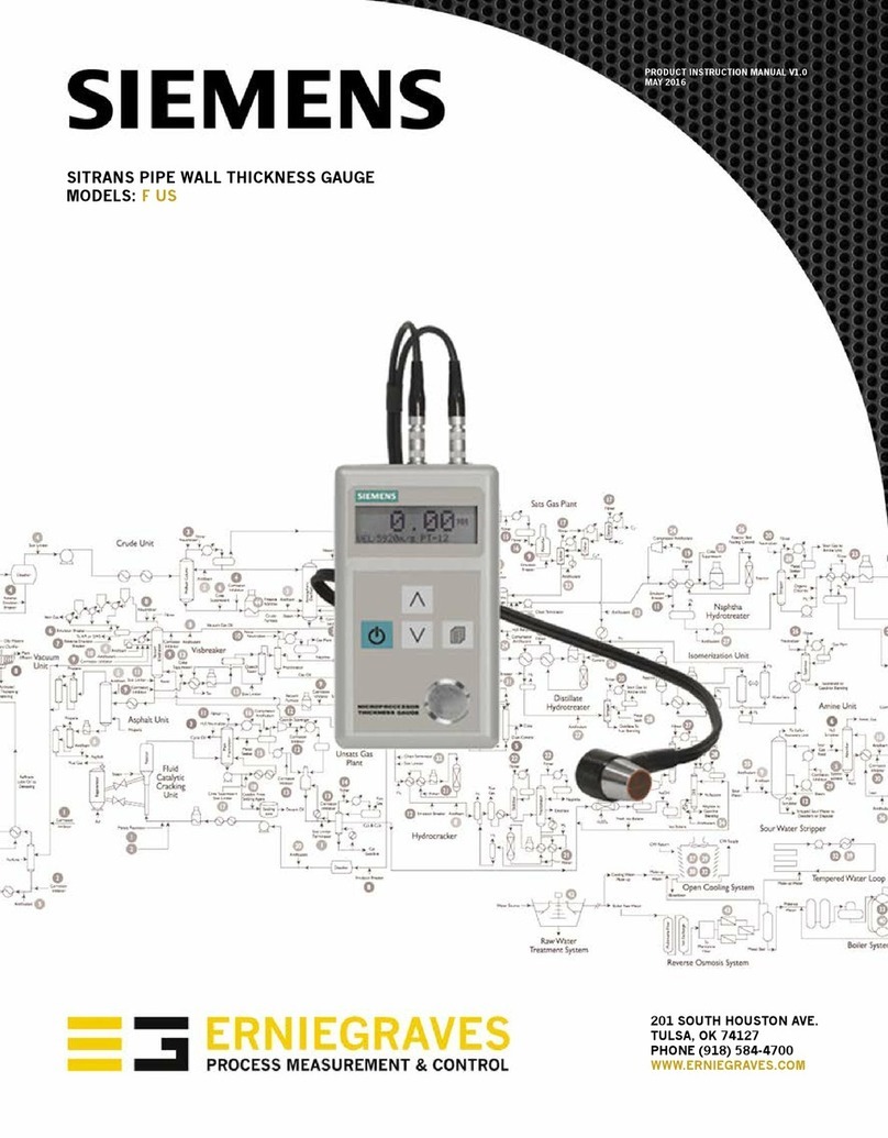
Siemens SITRANS F US User manual

Siemens

Siemens SITRANS F US User manual

Siemens 9330 series User manual

Siemens

Siemens 9330 series User manual

Siemens SICAM MMU User manual

Siemens

Siemens SICAM MMU User manual

Siemens SICAM Q200 7KG97 User manual

Siemens

Siemens SICAM Q200 7KG97 User manual

Siemens SITRANS SCM IQ User manual

Siemens

Siemens SITRANS SCM IQ User manual

Siemens SITRANS F M MAG 3100 Operating and maintenance instructions

Siemens

Siemens SITRANS F M MAG 3100 Operating and maintenance instructions

Siemens Set CEM CERT User manual

Siemens

Siemens Set CEM CERT User manual

Siemens SITRANS F US SONOFLO SONOKIT User manual

Siemens

Siemens SITRANS F US SONOFLO SONOKIT User manual

Siemens 3WN1 Guide

Siemens

Siemens 3WN1 Guide

Siemens SITRANS TDL User manual

Siemens

Siemens SITRANS TDL User manual

Siemens LDS 6 User manual

Siemens

Siemens LDS 6 User manual

Siemens BTC-BR User manual

Siemens

Siemens BTC-BR User manual

Siemens SITRANS FS230 User manual

Siemens

Siemens SITRANS FS230 User manual

Siemens sitrans PROBE LU User manual

Siemens

Siemens sitrans PROBE LU User manual

Siemens FS20 Guide

Siemens

Siemens FS20 Guide

Siemens SITRANS F M MAG 3100 User manual

Siemens

Siemens SITRANS F M MAG 3100 User manual

Siemens SITRANS F M MAG 1100 User manual

Siemens

Siemens SITRANS F M MAG 1100 User manual

Siemens Sitrans F Series User manual

Siemens

Siemens Sitrans F Series User manual

Siemens as-interface ANALYSER 3RK1 904-3AB01 User manual

Siemens

Siemens as-interface ANALYSER 3RK1 904-3AB01 User manual

Siemens Cerberus CS1140 User manual

Siemens

Siemens Cerberus CS1140 User manual

Siemens SIPROCESS UV600 User manual

Siemens

Siemens SIPROCESS UV600 User manual

Siemens SITRANS F User manual

Siemens

Siemens SITRANS F User manual

Siemens milltronics ILE-37 User manual

Siemens

Siemens milltronics ILE-37 User manual

Siemens DCA Vantage Manual

Siemens

Siemens DCA Vantage Manual

Popular Measuring Instrument manuals by other brands

Synrad Firestar TI Series quick start guide

Synrad

Synrad Firestar TI Series quick start guide

ERL tesla lite quick start guide

ERL

ERL tesla lite quick start guide

CARLO GAVAZZI EM24 DIN manual

CARLO GAVAZZI

CARLO GAVAZZI EM24 DIN manual

Spectrum 3415F user manual

Spectrum

Spectrum 3415F user manual

AEMC 193-24-BK user manual

AEMC

AEMC 193-24-BK user manual

DeWalt DW03050-XJ user manual

DeWalt

DeWalt DW03050-XJ user manual

VERIS INDUSTRIES, INC. E31E Series installation guide

VERIS INDUSTRIES, INC.

VERIS INDUSTRIES, INC. E31E Series installation guide

BASI BUFM660 Series manual

BASI

BASI BUFM660 Series manual

Orno OR-DC-633 instruction manual

Orno

Orno OR-DC-633 instruction manual

Agilent Technologies 4349B manual

Agilent Technologies

Agilent Technologies 4349B manual

WEBTEC FlowHUB Series user manual

WEBTEC

WEBTEC FlowHUB Series user manual

SATO KEIRYOKI PC-5400TRH instruction manual

SATO KEIRYOKI

SATO KEIRYOKI PC-5400TRH instruction manual

TPI 777 quick start guide

TPI

TPI 777 quick start guide

Fuji Electric ZaFe instruction manual

Fuji Electric

Fuji Electric ZaFe instruction manual

MIB Flowmax 242i operating manual

MIB

MIB Flowmax 242i operating manual

Planar IT-081 operating manual

Planar

Planar IT-081 operating manual

Radiodetection C.A.T3V and Genny3 user guide

Radiodetection

Radiodetection C.A.T3V and Genny3 user guide

VOLTCRAFT BS-2.0/1m operating instructions

VOLTCRAFT

VOLTCRAFT BS-2.0/1m operating instructions

manuals.online logo
manuals.online logoBrands
  • About & Mission
  • Contact us
  • Privacy Policy
  • Terms and Conditions

Copyright 2025 Manuals.Online. All Rights Reserved.