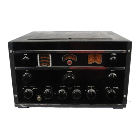
GENERAL PURPOSE COMMUNICATIONS
RECEIVER
MODEL
CR-91
TECHNICAL
SUMMARY
Electricel
Characterist
ics
Frequency
Range-tou!
6 bands
..
....
..
.....
.
....
..
.....
... ...
.
....
. . .
..
. . . . • . . . .
Band 1
....
. . .
...........
.
....
·
....
. ·
··
...•
·
··
···•
·
·.·•·
· · · ·
··
·
·•
· · ·
··
·
·· ··
Band 2
...
.
..
. . . . .
....
..
..
~
..
. . . .
....
. •
..
.
...
.
..
.
..
.. ..
..
..
.•
.
....
•. .
..
. .
...
Ba
nd
3 . .
...
.. ..
"
..
,
...•
,
..
..
.
•.
....•
'
..•
• . . • . . .
..
. .
•..
• . • . •
...
• . ' . ' .
....
.
Band 4. .
..
.
..................
.
......
. . .
..........
.
...
• . •
..
. . • . . • . . . . .
....
.
Ba
nd S
...
..
....
..
...
.
......
.
.....
..
....
..
..
.
..
,
··
...
.
··
..
. •
.. ..
.
..
....
.
...
Band 6
..
... ...
....
.. ..
....
. .
..
..
. .
.. ..
....
... ...
..
. • . . . . . .
...
•
..
.
.. ..
....
.
Maximum
Undist
o
ned
Ou
tp
ut
-
ap
proxim
ate-2.5
watts
Out
put
Impedance-2
.5
ohm
s and 600 ohm
s.
Power
Supply Requiremenb
7l
to :;0,500 kc
73 to 205 KC
195 to
55
0 kc
1,480 to 4,4
00
kc
4,250 to 12,150 kc
11
,900 to 19,500 kc
19,0
00
to
:iO
,500 kc
Line
Ratin
g
..
.
..
.
.. ..
. .
.. ..
. .
..
..
.
..
. 100·r17, 117·135
,135·1
65
,190·23
0,2
00·260
vo
lts, 50/ 60 cycles
.or
&t
te
rie,s
. .
....
...
....
.
....
.
.....
.
...
.
..
...
.
..
6 volt
"A
" ba
tt
ery and 250
[0
l
OO
volt
"B"
b
att
ery.
or
Vibrat
or
Po
w
er
Supply
Un
it .
...
....
..
..
. .
..
..
. .
MI
·8319.
Power
Co
ns
um
pti
on- l00
watt
s.
Tube
Complement
R·P a
nd
I-F A mp
lifi
er
s. .
..
..
.
..
.
..
•..
....
........
........
. .
•.
.....
. .
....
.. ..
1st
Dete
ctor
(c
on
ve
rte
r)
......
.
.•
. • . .
..
•..
• . . .
..
. •
..
. •• . • .
...
• . . . .
...
....
..
.
Oscillator . . .
...
"
..
. . , . .
..
. ,
•.
, . . • .
..
,.
,
..
. . .
..
. .
.•
. . .
.•
. . , . • . • •.
..
...•
. . ,
2n
d
Dete
cto
r·
.
..
.
.. ..
. .
..
.
..
.
•.
.
.. ..
•..•.
. . . •.
.•
.•..
..
.....
•
....•
. .
..
. . • .·
..
N·
L'
.
Olse:
Im
ltu
. . . . . . .
.....
.
...••
. .
•••
• . • • • • • • • ·
..
• •
•.
• . . ·
••
• .
····
• .
•.
.•
· •
··.
A·p
Am
p
li
fier
.....
...
, . .
.. ..
• . .
•.
•
...
. • . . . . • , . . ,
•.
• . • •. • . .
•.
• . . • •
..•
..
• .
..
Power Amplifier .
..
.
..
.
.. ..
. .
..
.
.. ..
.•..
. . •
....
. . .
.•
...
. •
..
..•
..
. . . ,
...
..
. .
Beat
Freq
uency
Osc
illator . .
...
..
•..
. . • .
..
• . . ,
...
..•
...
.
•....
.
..
...
..
. . •.
....
R
ec
tiner
..........
.
.....
.
..
.
•.
, • . . , '
•..
. . • . . . ,
..
•..
.••
......
,
...
•..
.
••.
, . . .
Voltage Regulator
....
.. ..
. .
..
. • . • . .
.. ..
..
.
..
, .
..
....
..
....
..
....
. . .
...
..
. . .
MeCMnicel
Spe.cific:ations
5 RCA·6SG7
1
RCA
-6SA7
1 RCA.6J5
1
RCA
·6
H6
1 RC
A·
6H6
1
RC
A
·6S
]7
1
RCA
6V6GTIG
1 RCA·6J5
1 RCA
·5
Y3GT/ G
1
RCA-VR·15
0
Ov
erall
Dime
nsi
ons
....
.
..
.
..
.
.....
..
....
..
....
. 19l,4 inc
hes
wide x
11
inches
high
x 191
/
..
inc
hes
d
ee
p
TABLE
I-
PERFORMANCE
DATA
(Appr
oximate
Values--Taken
on
Sample
Recei
ver)
Sens
itivity
Anten
na
Input
in
Ant
enna
Inpu
t in
Band
in M
ic
rovolts Mic
rov
olts for :20
DB
Microvolts f
or
20
DB
Image
N
o.
M
e:
gacycJes
for
0.5 waU Signal·Noi
r.e
Ratio Signal·Noire
Ra
tio
Ra
tio
1 .077
.5
1.8 10.0
.1
40 .5
1.
8 10.0 Great
e:
r
th
an
.190
.5
1.8 10.0 1,000,000
2 .205
.6
1.0 7.0
,375
••
1.
0 8.0 G reater
th
an
.5
00
••
1.5
10.0 1,000,000
3 •
I.
• .5
1.5
11.0 1,000,0
00
3.0 .7 1.3 1
0.
0
4.0
.5
1.3 1
0.
0 25,
000
,
4.5
••
2.0 12.0 500,000
1
1.
0
••
1.5
10.0 9,000
5 12.4 1.0 2.0 n.o 15,000
19.0
.5
2.0 12.0 3,5
00
6 20.0
2.0
2.0 11.0 3,5
00
30.0
1.
0 2.0
13
,0
600
• . .
I-F
reje
ctIOn
at
1600
kc IS
800.
000
. 4
.
