4
www.ReallyRightStuff.com
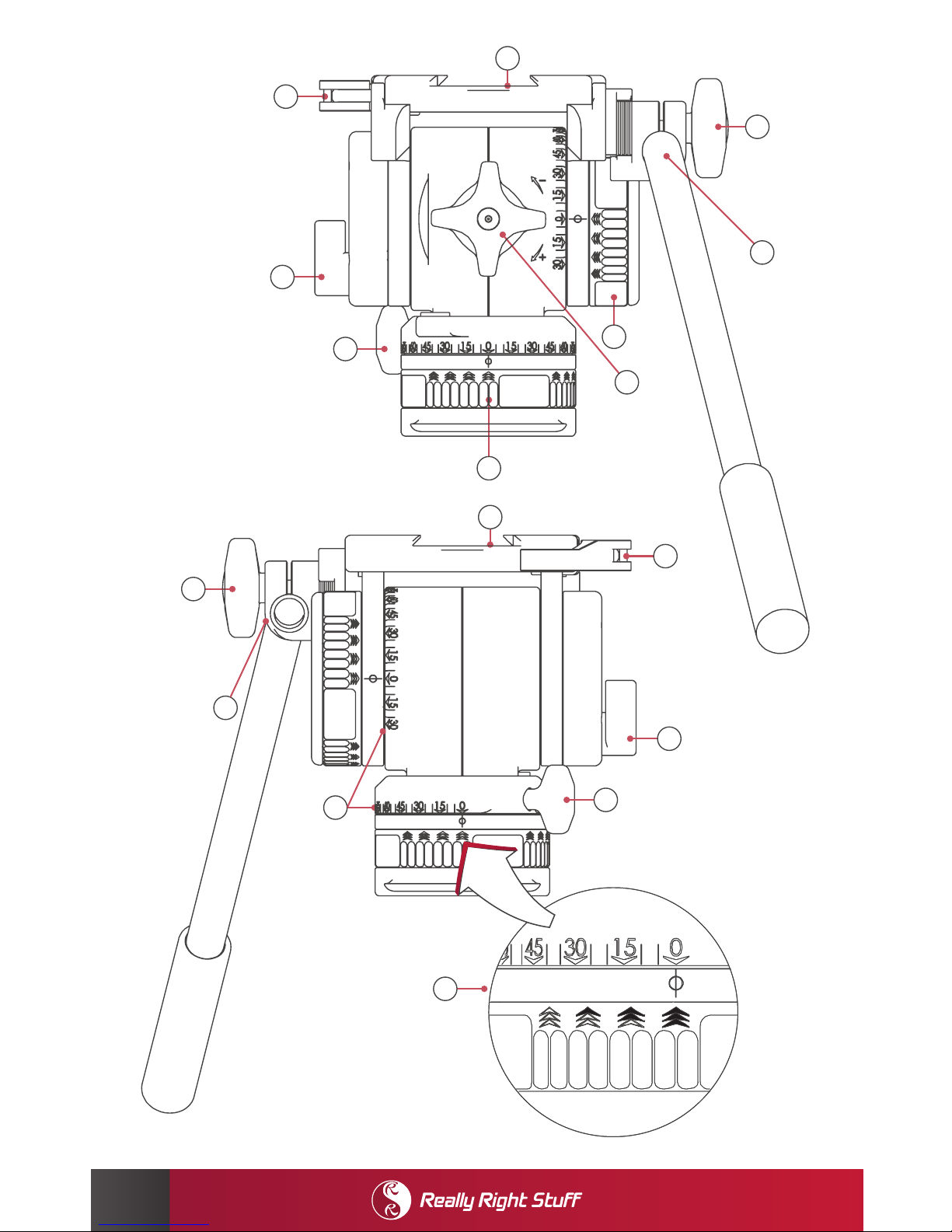
KEY FEATURES
1. Multi-Lock Swivel — Patent Pending swappable Handle & Multi-Lock Swivel deliver solid
control for your fluid head. Loosening the Multi-Lock Swivel allows you to position your
handle precisely where you want it, then lock it down by tightening the Handle Lock Knob.
This gives you the flexibility and reliability conventional toothed designs cannot.
2. Handle — The 15 inch aluminum Handle with grip can be installed on either side of the
fluid head. No tools required; rotate Handle Lock Knob to release Multi-Lock Swivel, then
swap sides and tighten in place.
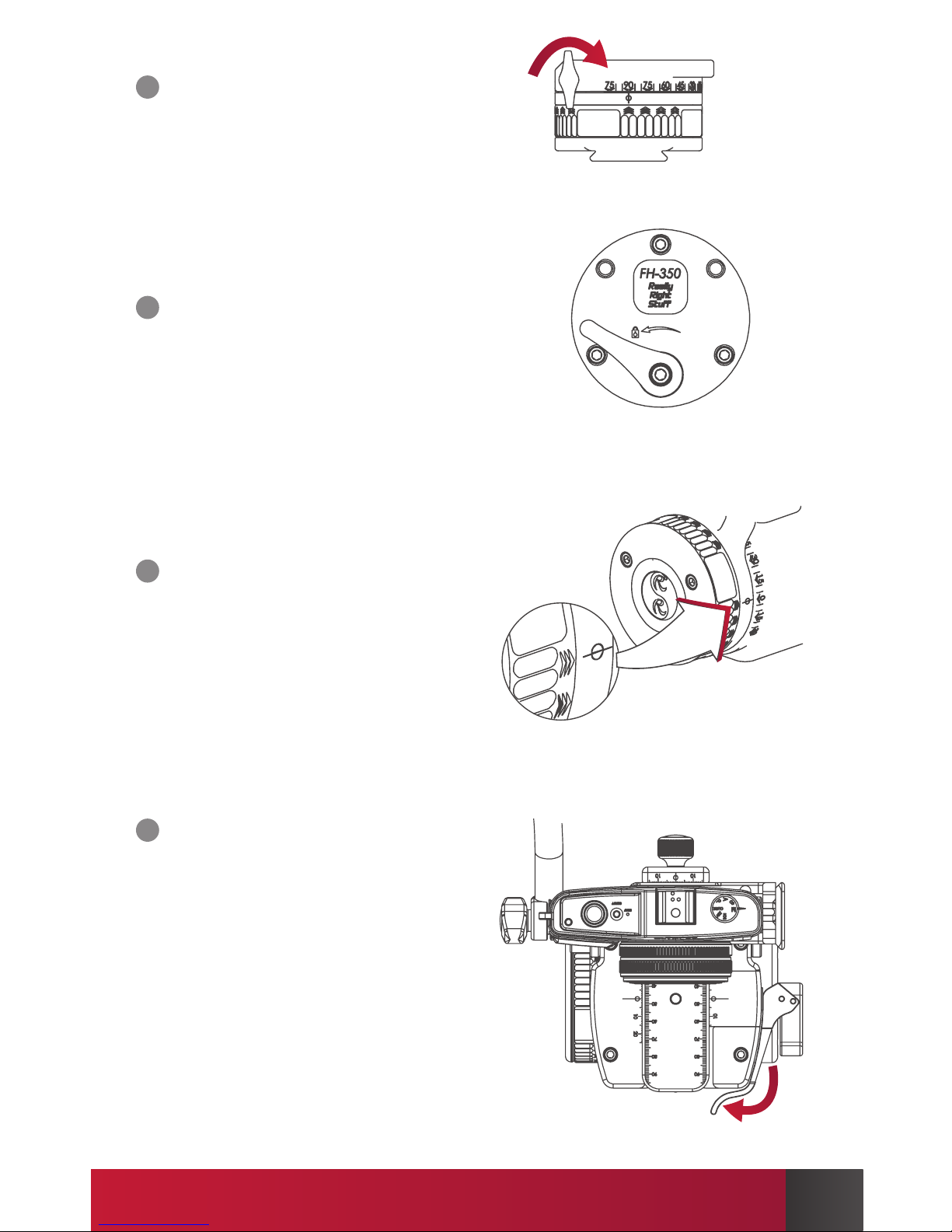
3. Tilt Damping Adjustment Wheel — Rotate wheel to adjust tilt damping. Chevrons
align with index mark in four positions to deliver: O (empty chevrons), Low, Medium,
and High (filled chevrons) levels of fluid damping. Note that there is no damping between
the chevron marks.
4. Counterbalance Adjustment Knob — Rotate the Counterbalance Adjustment Knob
clockwise to increase the counterbalance restoring torque. Decrease the counterbalance
restoring torque by rotating the knob in the counter-clockwise direction.
5. Pan Damping Adjustment Wheel — Similar to Tilt-Damping Adjustment Wheel, rotate
the Pan Damping Adjustment Wheel to change the level of fluid damping. There are no
intermediate settings between the chevron marks.
6. Pan Lock Knob — Rotate the Pan Lock Knob clockwise to tighten the panning base and
prevent rotation. Rotate a single turn counter-clockwise in order to loosen the panning base.
Partially engaging the pan lock is not recommended. Note that the knob can be removed
for replacement by continuing to turn the knob counterclockwise.
7. Tilt Lock Lever — Rotate the Tilt Lock Lever toward the direction of the Lock symbol on the
arrow to lock the head’s tilt axis at any position. Loosen the tilt axis by rotating the lever the
opposite direction. Note that the lever is captive and is factory-set with the proper amount
of clamping force. User adjustment is not required.
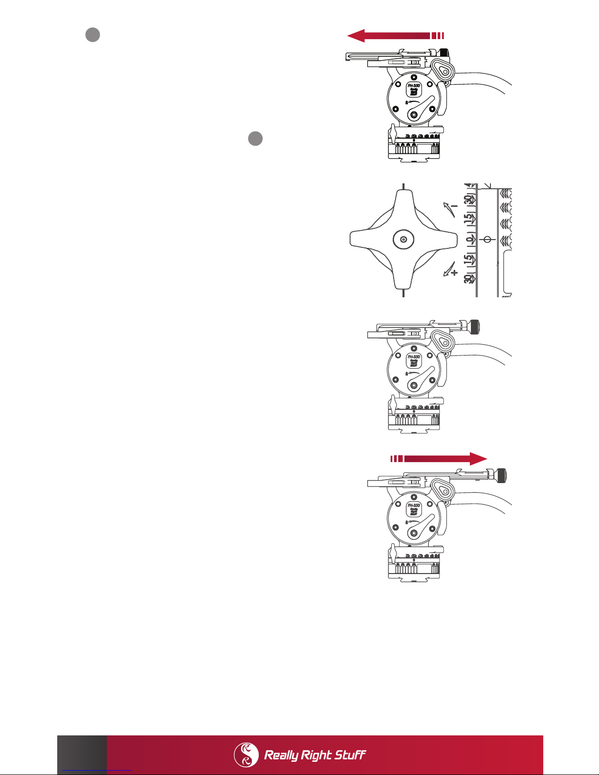
8. Clamp Lever — The clamp lever incorporates a Release Latch. To open the lever, first press
the Release Latch, then swing lever open 90°; this is the fully open position. The clamp is
fully closed and locked on the quick-release plate when the lever is firmly closed back to its
original position. Rotate the lever 45° to the half-open position to enable rail to slide fore & aft.
9. Quick-Release Clamp — Lever-release clamp* accepts all Really Right Stu-compatible
plates and rails. Clamp jaws are laser engraved in 1mm increments from (+)25- 0 - (-)25 on
center. Dual index marks aid positioning.
10. Precision Laser Markings — Use precision laser markings on the pan and tilt axes to
produce repeatable positioning of the fluid head. Tilt axes are laser engraved in 5° increments;
numbers and chevrons are lasered in 15° increments.
11. Circular Spirit Level— (not visible at le) Use the spirit level to ensure the pan axis is level
with the horizon. Center the bubble in the circle marked on the top of the spirit level. Tilting
the head forward, locking it at 45°, and viewing the bubble directly downward will produce
the most accurate bubble reading.
* Clamp automatically adjusts to accept all Arca-Swiss style plates except Arca-Swiss P0 (“PZero”) Slidefix
plates or plates made by Novoflex.