manuals.online logo
Brands
  1. Home
  2. •
  3. Brands
  4. •
  5. red lion
  6. •
  7. Control Unit
  8. •
  9. red lion ICM4 User manual

red lion ICM4 User manual

1
zALLOWS COMMUNICATIONS BETWEEN RS232 CONTROL
EQUIPMENT AND PRODUCTS WITH RS485 SERIAL
COMMUNICATIONS
zWIDE DC INPUT POWER RANGE (+9 to 32 VDC)
zHALF DUPLEX (RS485) AND FULL DUPLEX (RS422)
zLED INDICATION FOR RXD, TXD, and POWER
zUNIVERSAL MOUNTING FOOT FOR DIN RAIL INSTALLATION
DESCRIPTION
The ICM4 Serial Converter Module provides the capability of interfacing
equipment with RS485 serial communications to equipment with RS232
communications. Data format of the RS232 and RS485 equipment must be
the same.
For full duplex (RS422), the DIP switch on the side of the module must be in
the RS422 position. For half duplex (RS485), the DIP switch must be in the
RS485 position. In half duplex mode, the RS485 driver is enabled using the
leading edge of the first character transmitted (RXD input). After the last
character transmits, the converter waits one character time (at 9600 baud) to
disable the RS485 driver.
There are 3 LED’s that can be viewed from the front of the converter module.
A green power LED indicates power is on, a red RS232 TXD LED flashes when
the module is transmitting, and a green RS232 RXD LED flashes when the
module is receiving.
An external DC power source (+9 to 32 VDC) is required to power the ICM4.
The external power source and serial communications connections are made via
a 12 position removable terminal block located on the front of the module.
The unit is equipped with a universal mounting foot for attachment to
standard DIN style mounting rails, including top hat profile rail according to
EN50022 - 35 x 7.5 and 35 x 15, and G profile rail according to EN50035 - G32.
SAFETY SUMMARY
All safety related regulations, local codes and instructions that appear in the
manual or on equipment must be observed to ensure personal safety and to
prevent damage to either the instrument or equipment connected to it. If
equipment is used in a manner not specified by the manufacturer, the protection
provided by the equipment may be impaired.
SPECIFICATIONS
1. POWER: +9 to 32 VDC @ 75 mA maximum. Above 26 VDC, derate max.
operating temperature to 40°C. Power supply must be Class 2 or SELV rated.
2. RS232 VOLTAGES:
Receive Data Pin: ± 30 VDC max.
Mark Condition: ≤ 0.8 VDC
Space Condition: ≥ 2.4 VDC
Transmit Data Pin:
Mark Condition: −8 VDC (typ.)
Space Condition: +8 VDC (typ.)
3. RS485 VOLTAGES:
Differential Output Voltage: ± 5 VDC max. under no load
Differential Input Voltage: ± 5 VDC max.
Mark Condition: ≤ −0.2 VDC
Space Condition: ≥ +0.2 VDC
RS485 Drive Capability: Up to 32 RS485 receivers connected in parallel.
RS485 Drive Disable Time: 4 msec. max.
4. MAXIMUM CABLE LENGTH:
RS232: 50 feet
RS485: 4000 feet
5. BAUD RATE: 9600 min., 19200 max.
6. CERTIFICATIONS AND COMPLIANCES:
SAFETY
UL Recognized Component, File #E179259, UL3101-1, CSA C22.2 No.
1010-1
Recognized to U.S. and Canadian requirements under the Component
Recognition Program of Underwriters Laboratories, Inc.
IECEE CB Scheme Test Certificate # US/5141B/UL,
CB Scheme Test Report # 01ME11540-0702001
Issued by Underwriters Laboratories, Inc.
IEC 61010-1, EN 61010-1: Safety requirements for electrical
equipment for measurement, control and laboratory use, Part 1.
ELECTROMAGNETIC COMPATIBILITY
Refer to EMC Installation Guidelines for additional information.
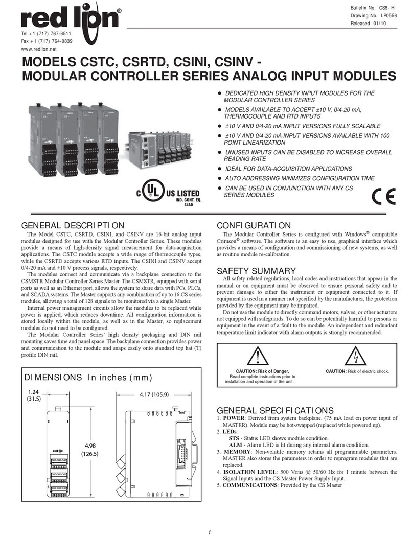
MODEL ICM4 - SERIAL CONVERTER MODULE (RS232C/RS485)
DIMENSIONS In inches (mm)
CAUTION: Risk of Danger.
Read complete instructions prior to
installation and operation of the unit.
Bulletin No. ICM4-D
Drawing No. LP0416
Released 3/07
Tel +1 (717) 767-6511
Fax +1 (717) 764-0839
www.redlion.net
UL Recognized Component,
File # E179259
900 MHz ± 5 MHz
Immunity to EN 50082-2
200 Hz, 50% duty cycle
Electrostatic discharge EN 61000-4-2 Level 2; 4 Kv contact
Level 3; 8 Kv air
Electromagnetic RF fields EN 61000-4-3 Level 3; 10 V/m
80 MHz - 1 GHz
Fast transients (burst) EN 61000-4-4 Level 4; 2 Kv I/O
Level 3; 2 Kv power
RF conducted interference EN 61000-4-6 Level 3; 10 V/rms
150 KHz - 80 MHz
Simulation of cordless telephone ENV 50204 Level 3; 10 V/m
Emissions to EN 50081-1
RF interference EN 55022 Enclosure class B
2
SPECIFICATIONS (Cont’d)
7. ENVIRONMENTAL CONDITIONS:
Operating Temperature Range: 0 to 50°C. Derate max. operating
temperature to 40°C above 26 VDC.
Storage Temperature: -40 to + 75°C
Operating and Storage Humidity: 85% max.relative humidity
(non-condensing) from 0 to 50°C
Altitude: Up to 2000 meters
8. CONSTRUCTION: Case body is black, high impact plastic. Installation
Category I, Pollution Degree 2.
9. MOUNTING: Standard DIN rail top hat (T) profile rail according to
EN50022- 35 X 7.5 and 35 X 15
10. WEIGHT: 3.2 oz. (90.7 g)
EMC INSTALLATION GUIDELINES
Although this unit is designed with a high degree of immunity to
ElectroMagnetic Interference (EMI), proper installation and wiring methods
must be followed to ensure compatibility in each application. The type of
electrical noise, source or coupling method into the unit may be different for
various installations. In extremely high EMI environments, additional measures
may be needed. Cable length, routing and shield termination are very important
and can mean the difference between a successful or a troublesome installation.
Listed below are some EMC guidelines for successful installation in an
industrial environment.
1. DC power to the unit should be relatively clean and within the specified
limits. Connecting power to the unit from circuits that power inductive loads
that cycle on and off, such as contactors, relays, motors, etc., should be
avoided. This will reduce the chance of noise spikes entering the DC power
connection and affecting the unit.
2. The shield (screen) pigtail connection should be made as short as possible.
The connection point for the shield depends somewhat upon the application.
Listed below are the recommended methods of connecting the shield, in
order of their effectiveness.
a. Connect the shield only at the unit to earth ground (protective earth).
b. Connect the shield to earth ground at both ends of the cable, usually when
the noise source frequency is above 1 MHz.
c. Connect the shield to common of the unit and leave the other end of the
shield unconnected and insulated from earth ground.
3. Never run Signal cables in the same conduit or raceway with AC power lines,
conductors feeding motors, solenoids, SCR controls, and heaters, etc. The
cables should be run in metal conduit that is properly grounded. This is
especially useful in applications where cable runs are long and portable two-
way radios are used in close proximity or if the installation is near a
commercial radio transmitter.
4. Signal cables within an enclosure should be routed as far away as possible
from contactors, control relays, transformers, and other noisy components.
5. In extremely high EMI environments, the use of external EMI suppression
devices, such as ferrite suppression cores, is effective. Install them on Signal
cables as close to the unit as possible. Loop the cable through the core several
times or use multiple cores on each cable for additional protection.
Install line filters on the power input cable to the unit to suppress power line
interference. Install them near the power entry point of the enclosure. The
following EMI suppression devices (or equivalent) are recommended:
Ferrite Suppression Cores for signal cables:
Fair-Rite # 0443167251 (RLC #FCOR0000)
TDK # ZCAT3035-1330A
Steward #28B2029-0A0
Line Filters for input power cables:
Schaffner # FN610-1/07 (RLC #LFIL0000)
Schaffner # FN670-1.8/07
Corcom #1VR3
Note: Reference manufacturer’s instructions when installing a line filter.
6. Long cable runs are more susceptible to EMI pickup than short cable runs.
Therefore, keep cable runs as short as possible.
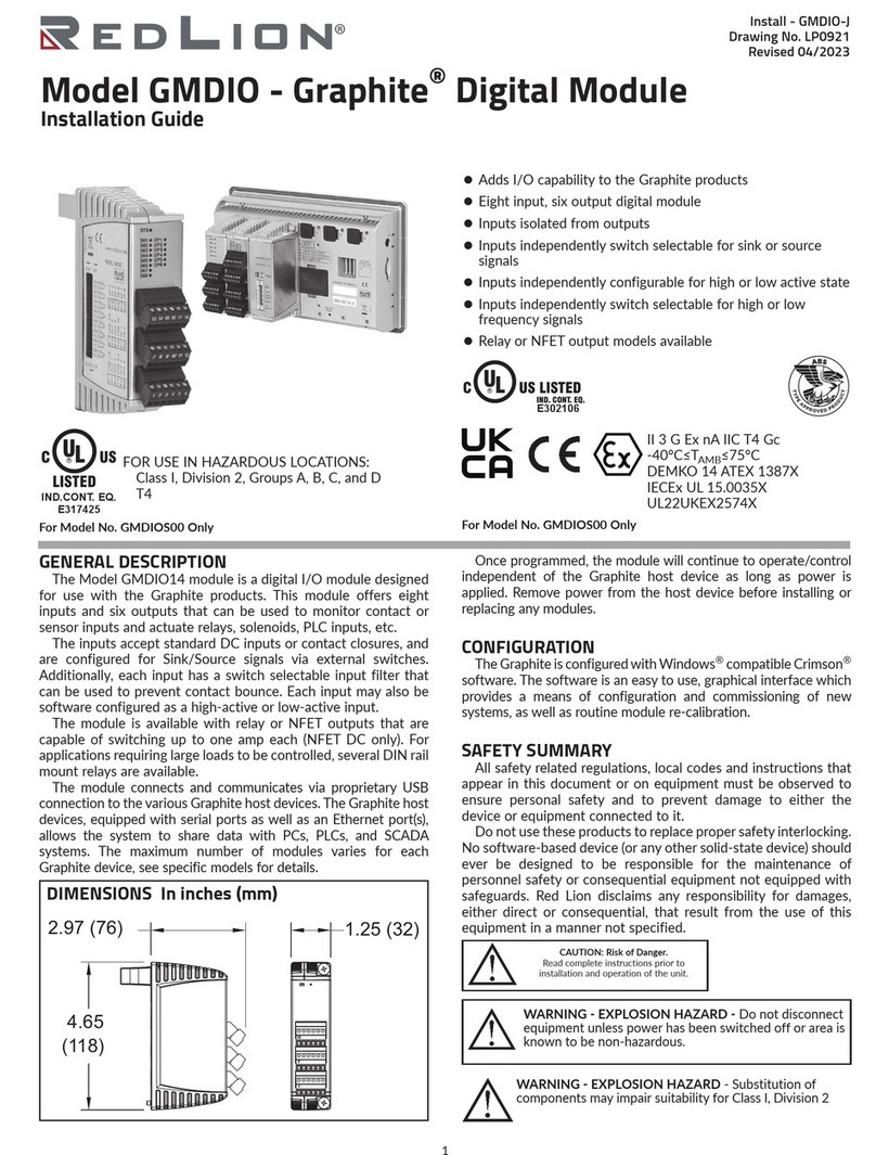
TYPICAL RS422 CONNECTIONS
Notes:
1. Connect shield drain wire to earth ground.
2. Place DIP switch on the side of the ICM4 in the 422 position.
3. RS422 polarity: Terminal “A” is negative with respect to Terminal “B” in
the mark (logic 1) condition.
SIDE VIEW OF ICM4
3
TYPICAL CONNECTION FOR MULTIPLE UNITS
TYPICAL CONNECTION FOR SINGLE UNIT
TYPICAL RS485 CONNECTIONS
Notes:
1. Connect shield drain wire to earth ground.
2. Place DIP switch on the side of the ICM4 in the 485 position.

3. The transmit and receive data lines of the ICM4 should be wired together.
TYPICAL RS232 CONNECTIONS
LIMITED WARRANTY
The Company warrants the products it manufactures against defects in materials and workmanship
for a period limited to two years from the date of shipment, provided the products have been stored,
handled, installed, and used under proper conditions. The Company’s liability under this limited
warranty shall extend only to the repair or replacement of a defective product, at The Company’s
option. The Company disclaims all liability for any affirmation, promise or representation with
respect to the products.
The customer agrees to hold Red Lion Controls harmless from, defend, and indemnify RLC against
damages, claims, and expenses arising out of subsequent sales of RLC products or products
containing components manufactured by RLC and based upon personal injuries, deaths, property
damage, lost profits, and other matters which Buyer, its employees, or sub-contractors are or may be
to any extent liable, including without limitation penalties imposed by the Consumer Product Safety
Act (P.L. 92-573) and liability imposed upon any person pursuant to the Magnuson-Moss Warranty
Act (P.L. 93-637), as now in effect or as amended hereafter.
No warranties expressed or implied are created with respect to The Company’s products except those
expressly contained herein. The Customer acknowledges the disclaimers and limitations contained
herein and relies on no other warranties or affirmations.
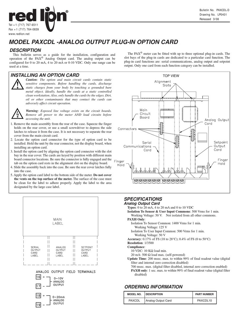
G Rail Installation
To install the ICM4
on a “G” style DIN
rail, angle the module
so that the upper
groove of the “foot”
catches under the lip of
the top rail. Push the
module toward the rail
until it snaps into
place. To remove a
module from the rail,
push up on the bottom
of the module while
pulling out away from
the rail.
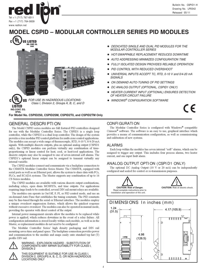
T Rail Installation
To install the
ICM4 on a “T” style
rail, angle the module
so that the top groove
of the “foot” is
located over the lip of
the top rail. Push the
module toward the
rail until it snaps into
place. To remove a
module from the rail,
insert a screwdriver
into the slot on the
bottom of the “foot”,
and pry upwards on
the module until it
releases from the rail.
INSTALLATION
The unit is equipped with a universal mounting foot for attachment to standard DIN style mounting rails, including G profile rail according to EN50035
- G32 , and top hat (T) profile rail according to EN50022 - 35 x 7.5 and 35 x 15. The unit should be installed in a location that does not exceed the maximum
operating temperature and provides good air circulation. Placing the unit near devices that generate excessive heat should be avoided.
TROUBLESHOOTING
For further technical assistance, contact technical support at the
appropriate company numbers listed.
ORDERING INFORMATION
MODEL NO. DESCRIPTION PART NUMBER
ICM4 RS232/RS485 Converter Module ICM40030
Red Lion Controls
20 Willow Springs Circle
York PA 17406
Tel +1 (717) 767-6511
Fax +1 (717) 764-0839
Red Lion Controls AP
31, Kaki Bukit Road 3,
#06-04/05 TechLink
Singapore 417818
Tel +65 6744-6613
Fax +65 6743-3360
Red Lion Controls BV
Printerweg 10
NL - 3821 AD Amersfoort
Tel +31 (0) 334 723 225
Fax +31 (0) 334 893 793

This manual suits for next models

1

Other red lion Control Unit manuals

red lion ITMA DC User manual

red lion

red lion ITMA DC User manual

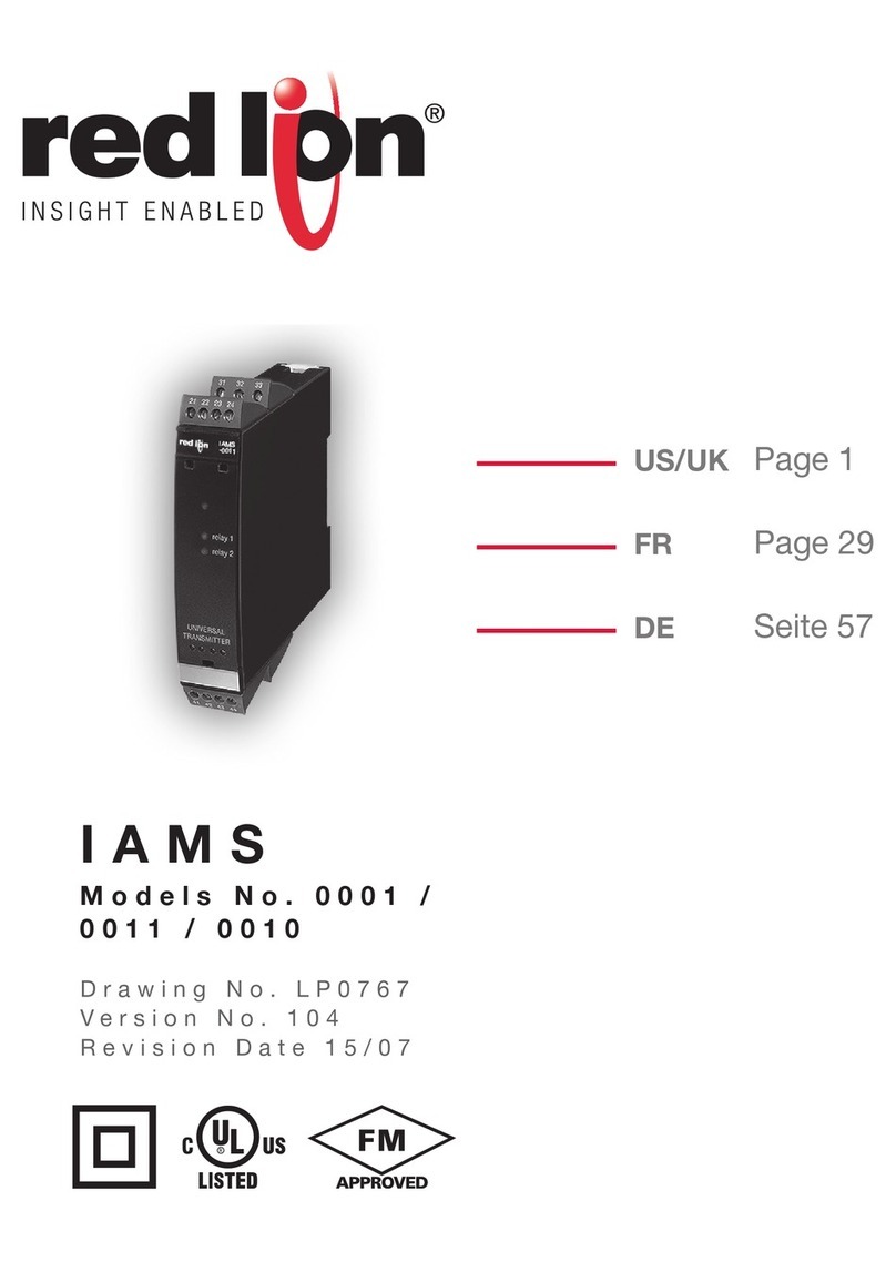
red lion IAMS 0001 User manual

red lion

red lion IAMS 0001 User manual

red lion XCPB Manual

red lion

red lion XCPB Manual

red lion ITMA User manual

red lion

red lion ITMA User manual

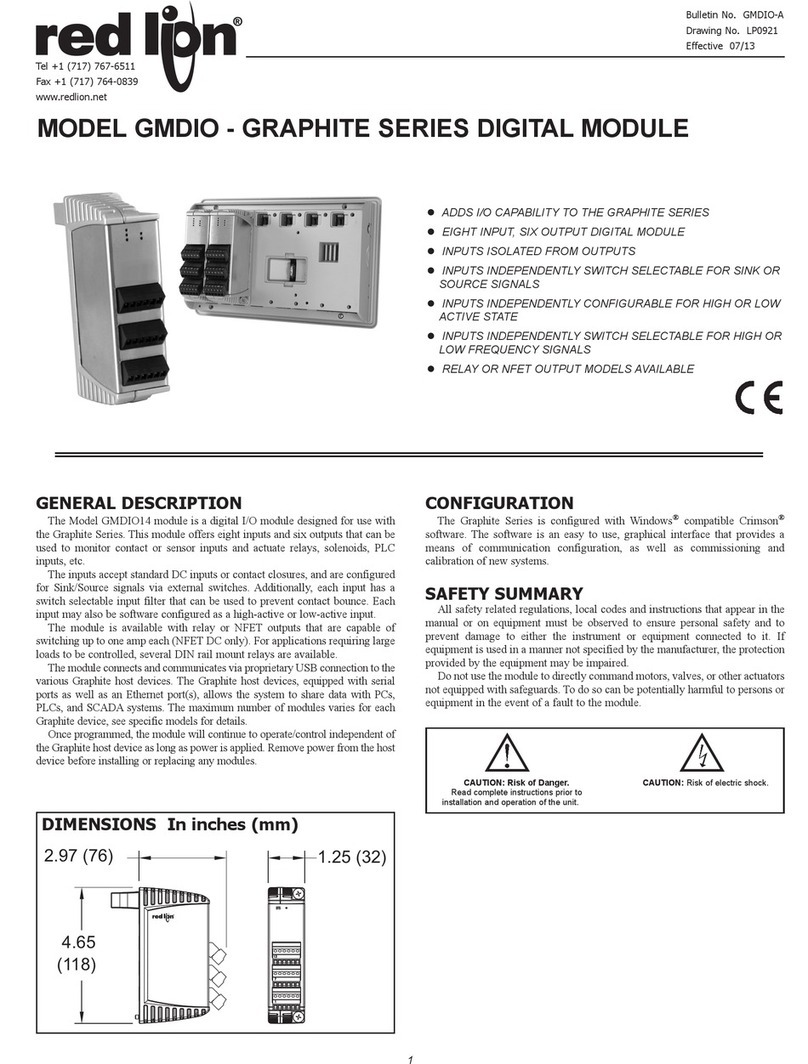
red lion Graphite GMDIO User manual

red lion

red lion Graphite GMDIO User manual

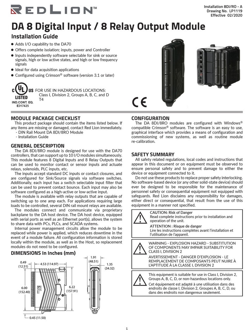
red lion DA Series User manual

red lion

red lion DA Series User manual

red lion ICM5 User manual

red lion

red lion ICM5 User manual

red lion DA 4G LTE CAT4 User manual

red lion

red lion DA 4G LTE CAT4 User manual

red lion ITMS4037 User manual

red lion

red lion ITMS4037 User manual

red lion GMDIO Series User manual

red lion

red lion GMDIO Series User manual

red lion MODULAR CONTROLLER SERIES User manual

red lion

red lion MODULAR CONTROLLER SERIES User manual

red lion PM-50 User manual

red lion

red lion PM-50 User manual

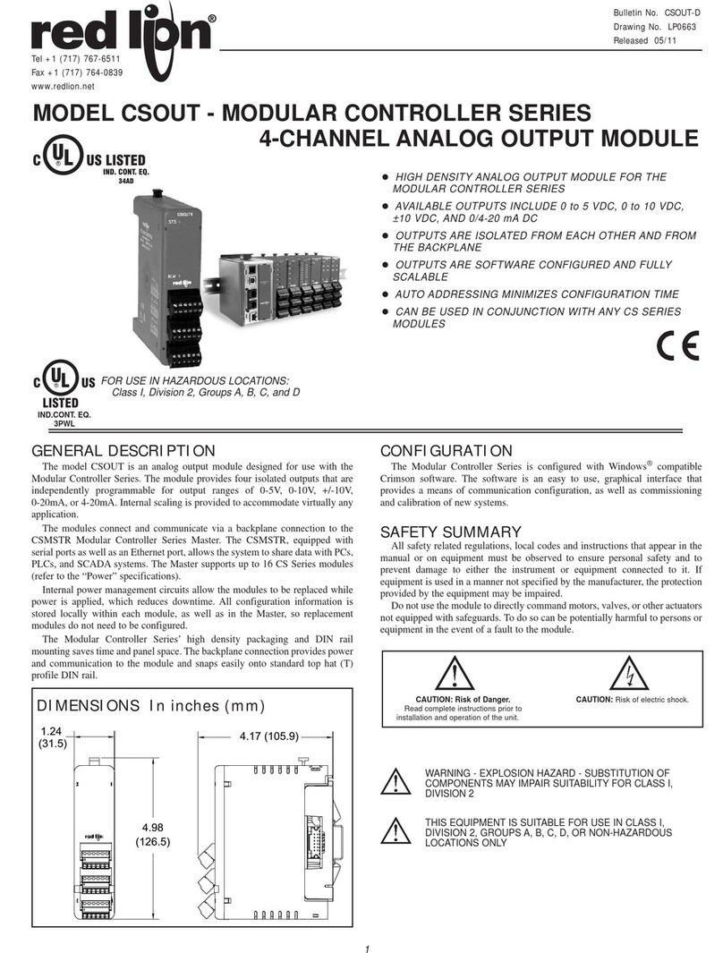
red lion CSOUT User manual

red lion

red lion CSOUT User manual

red lion PX2FCA User manual

red lion

red lion PX2FCA User manual

red lion IRMA DC User manual

red lion

red lion IRMA DC User manual

red lion IRMA User manual

red lion

red lion IRMA User manual

red lion Graphite Series Operating and maintenance instructions

red lion

red lion Graphite Series Operating and maintenance instructions

red lion Graphite GMUIN4 User manual

red lion

red lion Graphite GMUIN4 User manual

red lion Graphite GMSG1 User manual

red lion

red lion Graphite GMSG1 User manual

red lion Graphite GMJ1939 User manual

red lion

red lion Graphite GMJ1939 User manual

red lion CSTC User manual

red lion

red lion CSTC User manual

red lion CR3000 User manual

red lion

red lion CR3000 User manual

red lion Gemini 5200 User manual

red lion

red lion Gemini 5200 User manual

red lion PAXCDL User manual

red lion

red lion PAXCDL User manual

Popular Control Unit manuals by other brands

P.A. VS 1200 FL instructions

P.A.

P.A. VS 1200 FL instructions

Telit Wireless Solutions E922-3GR Series Hardware user's guide

Telit Wireless Solutions

Telit Wireless Solutions E922-3GR Series Hardware user's guide

Samson 3354 Mounting and operating instructions

Samson

Samson 3354 Mounting and operating instructions

Vag Figures 250-D Installation, operation and maintenance manual

Vag

Vag Figures 250-D Installation, operation and maintenance manual

Immotec iSafePro 360 VEXT-4 technical information

Immotec

Immotec iSafePro 360 VEXT-4 technical information

SMC Networks AV2000~5000-A Series instruction manual

SMC Networks

SMC Networks AV2000~5000-A Series instruction manual

Nibe SMO S40 user manual

Nibe

Nibe SMO S40 user manual

Burkert 8691 quick start

Burkert

Burkert 8691 quick start

Digital Equipment Pro-face GP-377R Series user manual

Digital Equipment

Digital Equipment Pro-face GP-377R Series user manual

Avidsen COMBO Kit SS1 manual

Avidsen

Avidsen COMBO Kit SS1 manual

Makel Energy Saver Assembly Diagram

Makel

Makel Energy Saver Assembly Diagram

vistaCNC iMachIII P1A-S manual

vistaCNC

vistaCNC iMachIII P1A-S manual

EisSound Audio Control Unit Installation & user manual

EisSound

EisSound Audio Control Unit Installation & user manual

ENERVEX MEC 18 Installation & operating manual

ENERVEX

ENERVEX MEC 18 Installation & operating manual

Festo VYKB-F10 operating instructions

Festo

Festo VYKB-F10 operating instructions

Mitsubishi Electric MELSEC iQ-R Series Safety guide

Mitsubishi Electric

Mitsubishi Electric MELSEC iQ-R Series Safety guide

EL.MO. Spa SCMAS5 Technical manual

EL.MO. Spa

EL.MO. Spa SCMAS5 Technical manual

Mitsubishi Electric CC-Link IE-NZ2GNSS2-8D user manual

Mitsubishi Electric

Mitsubishi Electric CC-Link IE-NZ2GNSS2-8D user manual

manuals.online logo
manuals.online logoBrands
  • About & Mission
  • Contact us
  • Privacy Policy
  • Terms and Conditions

Copyright 2025 Manuals.Online. All Rights Reserved.