manuals.online logo
Brands
  1. Home
  2. •
  3. Brands
  4. •
  5. Red Valve
  6. •
  7. Control Unit
  8. •
  9. Red Valve Tideflex Series User manual

Red Valve Tideflex Series User manual

IMPORTANT
Please take a moment to review this manual. Before performing any maintenance on the valve be sure that the pipeline has been depressurized. The improper
installation or use of this product may result in personal injury, product failure, or reduced product life. Tideex® can accept NO liability resulting from the improper
use or installation of this product. If you have any questions or problems, please call the customer service hotline at (412) 279-0044. We appreciate your comments.
Thank you for choosing Tideex®.
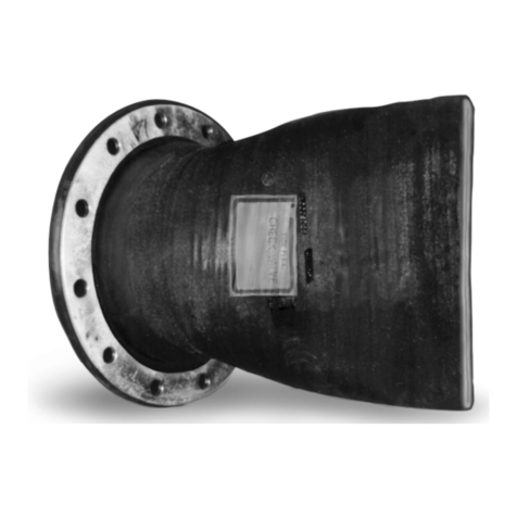
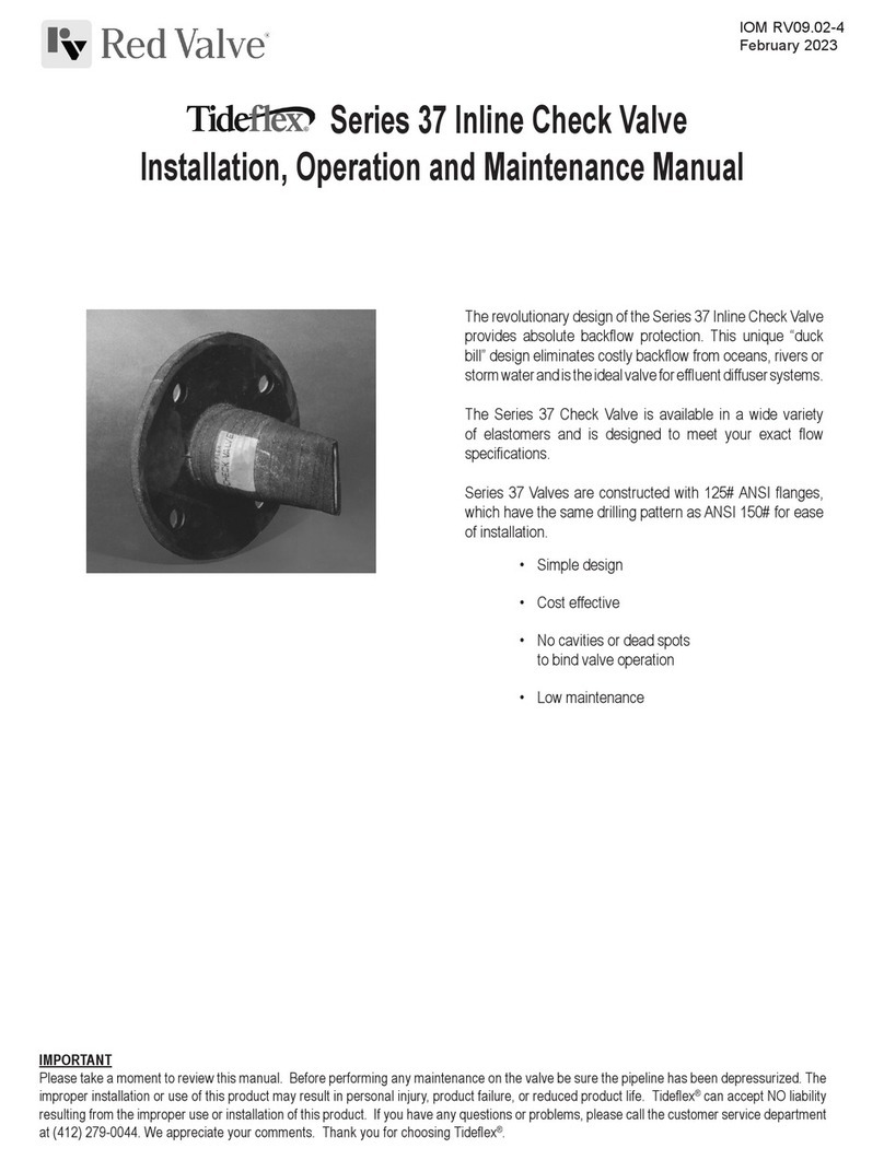
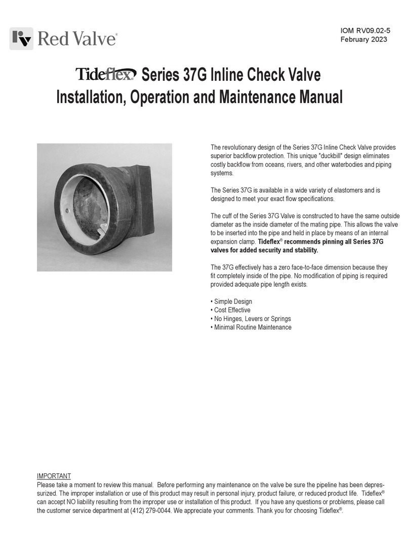
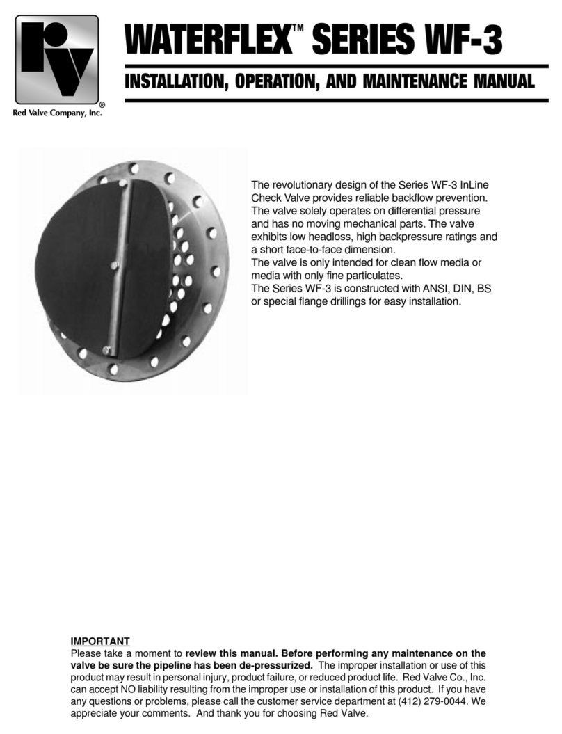
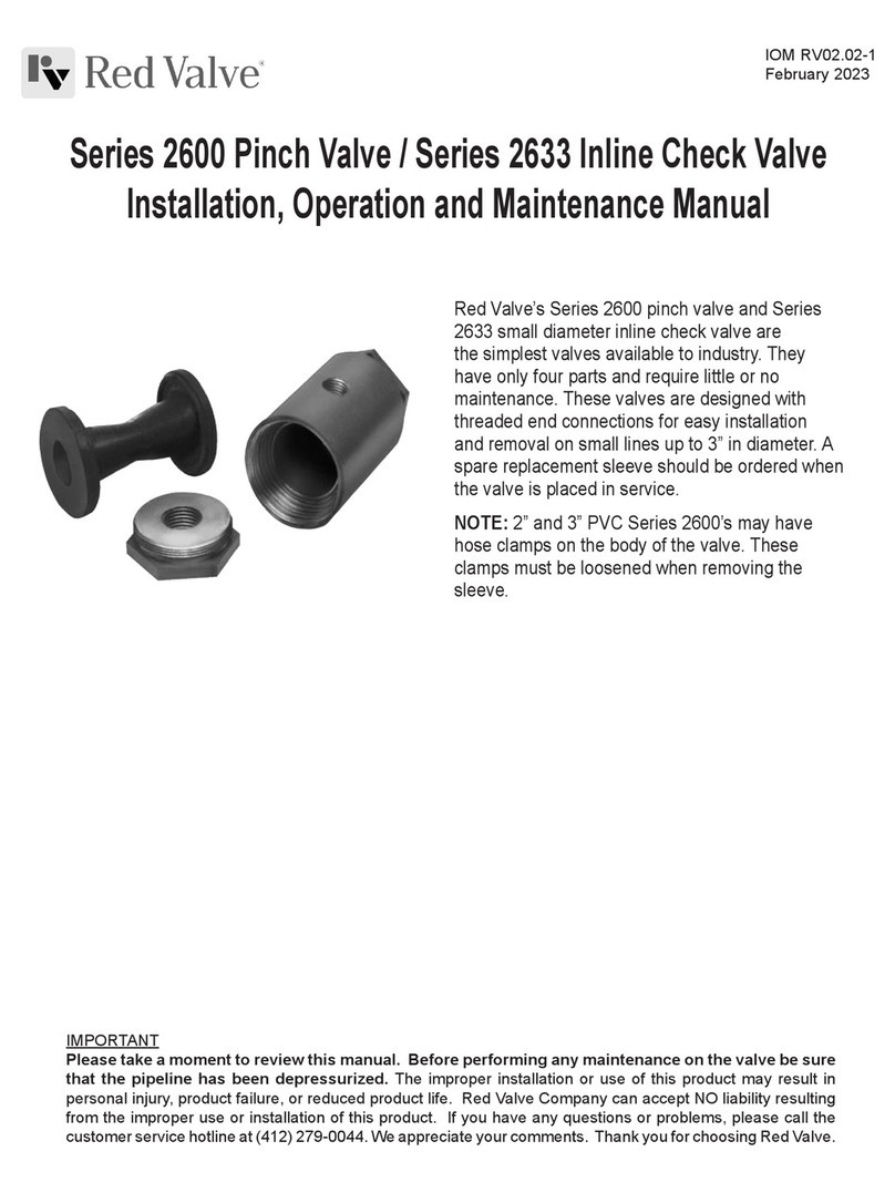
The revolutionary design of the Tideex® Series 39F Inline
Check Valve provides superior backow prevention. This
unique “duck bill” design eliminates costly backow from
oceans, rivers and streams and is the ideal valve for pump
stations.
The Series 39F uses proven Tideex®Check Valve
technology that provides low cracking pressures, low
headloss and the ability to operate in the harshest of
conditions. The exible rubber check valve resists
clogging and buildup of debris and it is available in several
different elastomers. The Series 39F will not slam, thereby
minimizing noise and vibration.
The Series 39F is more economical than other large-
diameter check valve designs because there are no moving
parts that require routing maintenance.
• Simple Design
• Cost Effective
• Low Maintenance
• No Seats
• No Hinges
Series 39F Inline Check Valve
Installation, Operation and Maintenance Manual
IOM RV09.02-7
February 2023
INSTALLATION
1. INSPECTION OF VALVE:
Inspect the body and mating anges for signs of damage. Check
all inspection and drain plugs to ensure that they are securely in
place. The mating upstream and downstream pipes should be
plumb and square to the 39F.
2. GASKETS:
The Series 39F contains a gasket between the body anges.
This gasket is formed from 1/8" thick rubber and seals the area
between the ID of the body ange and the inside of the bolt circle.
The body anges are serrated. Should the valve need to be
dismantled, new 1/8" thick gasket material must be obtained and
installed between the body ange ID and inside of the bolt circle.
There is a large inspection port at the top of the valve that is either
plugged or blind anged at the factory, and two drain ports at the
bottom of the valve, also plugged at the factory.
Pipe tape is used to ensure a tight seal. Gasket for the mating
upstream and downstream ange is supplied by others.
1. INSTALLING FLANGE BOLTS:
Insert the bolts and tighten in a star pattern. Tighten all bolts
uniformly so as to distribute pressure evenly around the ange.
2. VALVE ORIENTATION:
When the Series 39F is installed in a horizontal pipeline, the bill of
the internal Tideex
®
valve should be vertical.
3. EXTERNAL VALVE SUPPORT:
Valve supports must be supplied at the locations and dimensions
shown on the submittal drawing. The supports ensure the valve
and mating pipe are not exposed to excessive stress due to the
weight of the valve and water in it. Note, the support shown is cas
concrete, but support weldments are suitable provided they are
manufactured to the dimensions shown on the submittal drawing.
OPERATION
The Series 39F operates solely on differential pressure. Forward
differential pressure will cause the Tideex
®
Valve to open and discharge
the ow media. Reverse differential pressure with cause the Tideex
®
Valve to close preventing backow. The Series 39F Check Valve is a
self-contained check valve for use in gravity fed and pumped systems
provided the pressure conditions are within what was supplied when the
valve was ordered. The Tideex
®
check valve sleeve is fabricated based
on the maximum line and backpressure. Backpressure in excess of
the supplied backpressure may damage or invert the sleeve and cause
failure. Should the conditions for which the valve has been designed
be altered or changed in any way, it could affect the normal operation
of the valve. Consult the factory with the new system specications to
determine if the valve will operate properly.
Tideex®
Upstream Body
Body
Flange Clamps
Upstream
Flange
Body
Flange
Lifting
Lug
Drain Plugs
MAINTENANCE
1. INSPECTION:
The valve should occasionally be inspected for damage and wear.
The inspection period should be determined by the severity of the
service and environment. If the valve is periodically inspected and
preventative maintenance done, the valve will last longer and operate
better.
CAUTION: DO NOT REMOVE ANY PARTS WITH PRESSURE IN
THE PIPELINE.
There is a large inspection port
located at the top of the valve and
two drain plugs located at the
bottom of the valve. The internal
Tideex
®
check valve should be
periodically inspected for damage,
wear, or entrapped solids in the bill. All pressure must be removed
and the valve body should be drained prior to removing the
inspection plug. Following inspection of the valve, reinstall the
inspection plug (use pipe joint compound or tape) and tighten.
Downstream
Flange
Lifting
Lug
120o
Red Valve • 750 Holiday Drive, Suite 400, Pittsburgh, PA 15220 • 412-279-0044 • [email protected] • RedValve.com
© 2023 Red Valve Company
2.ELASTOMER SLEEVE REPLACEMENT
1. If the Tideex
®
valve needs to be replaced in the valve, the
following steps should be performed:
A. Remove internal pressure and drain water.
B. Remove bolts from mating anges.
C. Remove valve from the line and place on a solid, at surface
capable of supporting its weight.
D. Secure the upstream body half by suspending it from above. A
sling should be used around the pipe stub. DO NOT connect wire
or chain to the ange bolt holes, as this may damage the ange.
E. Slide the upstream body half and body out of the downstream half.
Place it on wood beams or another soft surface with the upstream
ange resting on the wood beams and the Tideex
®
valve pointing
vertically upward. Take care not to damage the ange.
CAUTION: The internal Tideex
®
check valve is clamped to the
upstream body half. It must be pulled out horizontally until the
internal Tideex
®
check valve is clear of the plate. Do not attempt
to lift the plate vertically. Damage to the Tideex
®
valve could
occur.
NOTE: Use the "Tideex
®
All-Rubber Check Valve" IOM for proper
handling, storage, and installation instruction for the Tideex
®
Check Valve.
F. Remove the bolts that are used as pins in the Tideex
®
clamps.
G. Loosen and remove the clamps.
H. Lift the Tideex
®
valve off of the pipe stub. Install the new Tideex
®
valve with the bill in the correct position (vertical after assembled)
onto the pipe stub. Ensure that the valve slides on the stub far
enough to hit the cuff stop. This will ensure the valve is properly
located.
I. Once the Tideex
®
valve is installed, locate the clamps on the cuff
and tighten. Rotate the "ears" of the clamp (90
o
for two clamps, 60
o
for three) to ensure an adequate seal around the cuff.
J. Use the four predrilled holes in each of the clamps as a template
and use a 1" drill bit to drill through the rubber cuff and through the
metal stub. Install the four 7/8" bolts in each clamp and tighten the
nuts to ensure valve is pinned to stub.
K. Wire brush the gasket material from both of the large body anges.
Attach 1/8" thick gasket material to the downstream body ange
and ll the area between the ID of the ange and the inside of the
bolt holes. Overlap any seams.
L. Slide the upstream body half, with Tideex
®
valve installed, into the
downstream body half. Line up the bolt holes. Install bolts and
tighten in a star pattern.
M.The valve is now ready to be reinstalled into the pipeline.
STORAGE
If your Series 39F Check Valve is to be stored for a period of
time prior to installation, the following storage guidelines will help
preserve your valve and ensure a trouble free installation.
1. Store in a clean, cool, dry area. Avoid exposure to light, electric
motors, dirt or chemicals.
2. Store valve in a manner to prevent other items from contacting the
check sleeve or anges to prevent possible damage.
3. Store this manual with the valve so that it is readily available at the
time of installation.
TROUBLESHOOTING GUIDE
SYMPTOM: VALVE WILL NOT CLOSE FULLY, OR CHECK
• Possible obstruction in line. Inspect the valve for entrapped foreign
objects which may have lodged between the lips of the valve.
• Ensure there is clearance below the Tideex
®
check Vvlve and the
bottom of the body.
• Backpressure may not be sufcient to completely seal the valve.
SYMPTOM: SLEEVE RUPTURE/INVERSION
• Excess backpressure. Verify static backpressure and identify possible
surge pressure or vacuum pressure.
SYMPTOM: LEAKING FROM FLANGES
• Loosen and retighten bolts in a star pattern to ensure even pressure
distribution around ange.
• If leakage persists, replace ange gasket and retighten bolts in star
pattern.
Upstream Body Half
Drain Plugs
Downstream Body Half
Inspection Ports
Red Valve • 750 Holiday Drive, Suite 400, Pittsburgh, PA 15220 • 412-279-0044 • [email protected] • RedValve.com
© 2023 Red Valve Company
Limited Warranty
Red Valve Company (“Seller”) manufactured products, auxiliaries and parts thereof that we manufacture for a period of twenty-four (24) months from
date of shipment from Seller’s factory, are warranted to the original purchaser only against defective workmanship and material, but only if properly
stored, installed, operated, and serviced in accordance with Seller’s recommendations and instructions.
For items proven to be defective within the warranty period, your exclusive remedy under this limited warranty is repair or replacement of the defective
item, at Seller’s option, FCA Incoterms 2020 Seller’s facility with removal, transportation, and installation at your cost.
Products or parts manufactured by others but furnished by Seller are not covered by this limited warranty. Seller may provide repair or replacement
for other’s products or parts only to the extent provided in and honored by the original manufacturer’s warranty to Seller, in each case subject to the
limitations contained in the original manufacturer’s warranty.
No claim for transportation, labor, or special or consequential damages or any other loss, cost or damage is being provided in this limited warranty.
You shall be solely responsible for determining suitability for use and in no event shall Seller be liable in this respect.
This limited warranty does not warrant that any Seller product or part is resistant to corrosion, erosion, abrasion or other sources of failure, nor does
Seller warrant a minimum length of service.
Your failure to give written notice to us of any alleged defect under this warranty within twenty (20) days of its discovery, or attempts by someone other
than Seller or its authorized representatives to remedy the alleged defects therein, or failure to return product or parts for repair or replacement as
herein provided, or failure to store, install, or operate said products and parts according to the recommendations and instructions furnished by Seller
shall be a waiver by you of all rights under this limited warranty.
This limited warranty is voided by any misuse, modification, abuse or alteration of Seller’s product or part, accident, fire, flood or other Act of God, or
your failure to pay entire contract price when due.
The foregoing limited warranty shall be null and void if, after shipment from our factory, the item is modified in any way or a component of another
manufacturer, such as but not limited to; an actuator is attached to the item by anyone other than a Seller factory authorized service personnel.
All orders accepted shall be deemed accepted subject to this limited warranty, which shall be exclusive of any other or previous warranty, and this
shall be the only effective guarantee or warranty binding on Seller, despite anything to the contrary contained in the purchase order or represented by
any agent or employee of Seller in writing or otherwise, notwithstanding, including but not limited to implied warranties.
THE FOREGOING REPAIR AND REPLACEMENT LIMITED WARRANTY IS IN LIEU OF ALL OTHER WARRANTIES, OBLIGATIONS AND
LIABILITIES, INCLUDING, BUT NOT LIMITED TO, ALL WARRANTIES OF FITNESS FOR A PARTICULAR PURPOSE OR OF MERCHANTABILITY
OR OTHERWISE, EXPRESSED OR IMPLIED IN FACT OR BY LAW, AND STATE SELLER’S ENTIRE AND EXCLUSIVE LIABILITY AND YOUR
EXCLUSIVE REMEDY FOR ANY CLAIM IN CONNECTION WITH THE SALE AND FURNISHING OF SERVICES, GOODS OR PARTS, THEIR
DESIGN, SUITABILITY FOR USE, INSTALLATION OR OPERATIONS. NEITHER ANY PERFORMANCE OR OTHER CONDUCT, NOR ANY ORAL OR
WRITTEN INFORMATION, STATEMENT, OR ADVICE PREPARED BY SELLER OR ANY OF OUR EMPLOYEES OR AGENTS WILL CREATE A
WARRANTY, OR IN ANY WAY INCREASE THE SCOPE OR DURATION OF THIE LIMITED WARRANTY.
Limitation of Liability
IN NO EVENT SHALL SELLER BE LIABLE FOR ANY DIRECT, INDIRECT, SPECIAL, PUNITIVE, EXEMPLARY, OR CONSEQUENTIAL DAMAGES
(INCLUDING, BUT NOT LIMITED TO, DAMAGE TO OR LOSS OF OTHER PROPERTY OR EQUIPMENT, BUSINESS INTERUPTION, COST OF
SUBSTITUTE PRODUCTS, LOSS OF TIME, LOSS PROFITS OR REVENUE, COST OF CAPITAL, LOSS OF USE, OR DIMINUTION IN VALUE)
WHATSOEVER, AND SELLER’S LIABILITY, UNDER NO CIRCUMSTANCES, WILL EXCEED THE CONTRACT PRICE FOR THE GOODS AND/OR
SERVICES FOR WHICH LIABILITY IS CLAIMED. ANY ACTION FOR BREACH OF CONTRACT BY YOU, OTHER THAN RIGHTS RESPECTING OUR
LIMITED WARRANTY DESCRIBED ABOVE, MUST BE COMMENCED WITHIN 12 MONTHS AFTER THE DATE OF SALE.
Sales and Service
For information about our worldwide locations, approvals, certifications and local representative:
Web site: RedValve.com E-Mail: [email protected]
750 Holiday Drive, Suite 400, Pittsburgh, PA 15220 • Phone: 412-279-0044
Red Valve Company reserves the right to incorporate our latest design and material changes without notice or obligation.
Design features, materials of construction and dimensional data, as described in this manual, are provided for your information only
and should not be relied upon unless confirmed in writing by Red Valve Company. Certified drawings are available upon request.
February 2023

This manual suits for next models

1

Other Red Valve Control Unit manuals

Red Valve Tideflex Series User manual

Red Valve

Red Valve Tideflex Series User manual

Red Valve Tideflex 35 Series User manual

Red Valve

Red Valve Tideflex 35 Series User manual

Red Valve 2600 Series User manual

Red Valve

Red Valve 2600 Series User manual

Red Valve TIdeFlex 37 Series User manual

Red Valve

Red Valve TIdeFlex 37 Series User manual

Red Valve Tideflex Series User manual

Red Valve

Red Valve Tideflex Series User manual

Red Valve WATERFLEX SERIES WF-3 Installation and operating instructions

Red Valve

Red Valve WATERFLEX SERIES WF-3 Installation and operating instructions

Red Valve G Series User manual

Red Valve

Red Valve G Series User manual

Red Valve Flexgate D series User manual

Red Valve

Red Valve Flexgate D series User manual

Red Valve 75 Series User manual

Red Valve

Red Valve 75 Series User manual

Popular Control Unit manuals by other brands

tedee BleBox smart installation manual

tedee

tedee BleBox smart installation manual

Hubbell GAI-TRONICS XCP0020A instructions

Hubbell

Hubbell GAI-TRONICS XCP0020A instructions

Beninca DA.C20 operating instructions

Beninca

Beninca DA.C20 operating instructions

WellMark 2001NB Series Installation, operation & maintenance instructions

WellMark

WellMark 2001NB Series Installation, operation & maintenance instructions

Leadshine Technology Co. EM870S user manual

Leadshine Technology Co.

Leadshine Technology Co. EM870S user manual

TP-Link kasa smart KE100 quick start guide

TP-Link

TP-Link kasa smart KE100 quick start guide

Stagnoli A24 instructions

Stagnoli

Stagnoli A24 instructions

Azbil ACTIVAL+ FVY513E Series Specifications & instructions

Azbil

Azbil ACTIVAL+ FVY513E Series Specifications & instructions

Assa Abloy OneSystem N5952 Installation instructions and functional description

Assa Abloy

Assa Abloy OneSystem N5952 Installation instructions and functional description

Allen-Bradley FLEX I/O 1794-OB8 installation instructions

Allen-Bradley

Allen-Bradley FLEX I/O 1794-OB8 installation instructions

SMC Networks VO317 Series Operation manual

SMC Networks

SMC Networks VO317 Series Operation manual

ADTRAN Job Aid+ 1442707G3 manual

ADTRAN

ADTRAN Job Aid+ 1442707G3 manual

Sundance Technology SMT351T user guide

Sundance Technology

Sundance Technology SMT351T user guide

Fagor CNC 8055 operating manual

Fagor

Fagor CNC 8055 operating manual

marklin 6021 quick start guide

marklin

marklin 6021 quick start guide

Digi Digi XBee SX user guide

Digi

Digi Digi XBee SX user guide

Copley Controls Corp. Accelnet Micro Module manual

Copley Controls Corp.

Copley Controls Corp. Accelnet Micro Module manual

FMS CMGZ432 operating manual

FMS

FMS CMGZ432 operating manual

manuals.online logo
manuals.online logoBrands
  • About & Mission
  • Contact us
  • Privacy Policy
  • Terms and Conditions

Copyright 2025 Manuals.Online. All Rights Reserved.