manuals.online logo
Brands
  1. Home
  2. •
  3. Brands
  4. •
  5. Red Valve
  6. •
  7. Control Unit
  8. •
  9. Red Valve Tideflex 35 Series User manual

Red Valve Tideflex 35 Series User manual

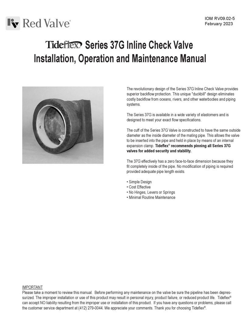
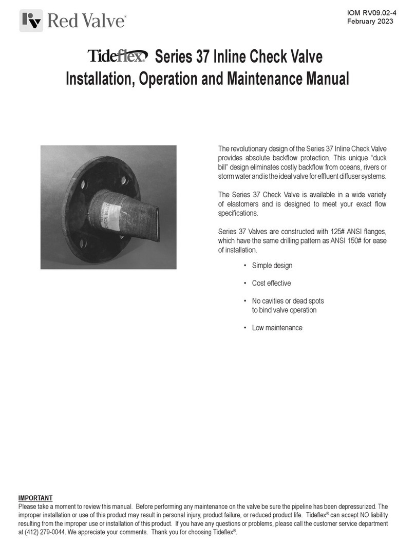
The revolutionary design of the Series 35/35-1 Check Valve
provides absolute backow protection. This unique "duck bill"
design eliminates costly backow from oceans, rivers or storm
water and is the ideal valve for efuent diffuser systems.
Series 35/35-1 Check Valves seal “drop tight” on entrapped
solids and debris without jamming. Unlike traditional ap gates
there are no hinged gates to hang open and no warping or
freezing. They’re maintenance–free.
The Series 35/35-1 Check Valve is available in a wide variety
of elastomers and is designed to meet your exact ow
specications.
IMPORTANT
Please take a moment to review this manual. Before performing any maintenance on the valve be sure the pipeline has been de-pressurized. The
improper installation or use of this product may result in personal injury, product failure, or reduced product life. Tideex®can accept NO liability
resulting from the improper use or installation of this product. If you have any questions or problems, please call the customer service department
at (412) 279-0044. We appreciate your comments. Thank you for choosing Tideex®.
IOM RV09.02-1
February 2023
Series 35 / Series 35-1 Check Valves
Installation, Operation and Maintenance Manual
INSTALLATION
The valve shall be installed with the bill in the vertical position. The valve
end with the rubber ange face should be installed on the pressure side of
the system using the split backup rings provided. The sleeve split should be
installed facing downstream, with the split in the vertical position.
The installation bolt torque on the end ange bolts are listed in the table below.
RECOMMENDED MINIMUM BOLT TORQUE
Valve Size Bolt Size Torque (ft*lb.)
1" 1/2" - 13NC 20
1-1/2" 1/2" - 13NC 20
2" 5/8" - 11NC 30
2-1/2" 5/8" - 11NC 40
3" 5/8" - 11NC 40
4" 5/8" - 11NC 30
5" 3/4" - 10NC 40
6" 3/4" - 10NC 30
8" 3/4" - 10NC 40
10" 7/8" - 9NC 40
12" 7/8" - 9NC 50
14" 1" - 8NC 50
16" 1" - 8NC 50
18" 1-1/8" - 7NC 30
20" 1-1/8" - 7NC 30
24" 1-1/4" - 7NC 40
30" 1-1/4" – 7NC 30
36" 1-1/2" – 6NC 40
42" 1-1/2" – 6NC 50
48" 1-1/2" – 6NC 55
54" 1-3/4"– 5NC 60
60" 1-3/4"– 5NC 80
72" 1-3/4"– 5NC 100
Torque values are suggested minimum values.
Torque all ange bolts in a star pattern, rst to 50% of tabulated values, then
retorque to 100% of tabulated values. If greater torque is required, continue
retorquing in increments of 50% of tabulated values. Use of a high quality
anti–seize compound on all bolt threads is recommended.
Variables such as the surface nish on bolt threads, type of anti–seize
compound used, and surface nish of the mating anges all have an effect
on the minimum torque required to obtain a leak–tight ange seal.
OPERATION
The Series 35/35-1 Check Valve is a self-contained check valve for use on
low back pressure systems. Back pressures in excess of rated pressure can
invert the sleeve and cause valve failure.
Tideex® check valves are custom made products intended for a specic
application and have been designed to respond to criteria unique to that
purpose, such as line pressure, minimum and maximum backow pressure,
and chemical compatibility. Should the conditions for which the valve has
been designed be altered or change in any way, it could affect the normal
operation of the valve, and/or prevent the valve from draining completely.
Valves made to withstand high back pressure may not self–drain
completely.
MAINTENANCE
The Series 35/35-1 Check Valve should remain trouble free for the life of the
system.
STORAGE
Rubber Check Valves should be stored in a cool, dry location on original
shipping pallet with the bill facing upward (not on side) (Figure #1). Do not
drop, bend or twist the Check Valve or damage may occur.
1. Store the valve in a cool, clean, dry location.
2. Avoid exposure to light, electric motors, dirt or chemicals. Resilient
Check Valves are subject to deterioration when exposed to ozones
and non-compatible chemicals.
3. Store Installation Operation Manual with product so it will be readily
available for installation.
FIGURE 1
TROUBLESHOOTING
During installation you may need to retorque the ange bolts several times for a
proper seal. This will overcome any leaks due to the cold ow of the rubber sleeve
ange.
A. Standard check valves are built to
schedule 40 pipe I.D. and to ANSI Class
125/150# ange and bolt circle speci-
cations. It is recommended that the
mating anges are at and full faced.
B. It is recommended that the mating
ange be serrated to “grip” the rubber
ange. The serrations should be cut
1/16" deep, with a 90° angle tool point.
The pitch should be 8 (eight) cuts per
inch.
C. Mating ange ID must match the
Check Valve sleeve ID.
D. When installing a check valve to
a rubber, PVC, or any “slick” mating
ange, we recommend that you install a
metal serrated gasket between the two
anges to assist in the seal.
E. When bolting a check valve to a PVC
or synthetic mating ange, use a split
back–up retaining ring, since the mating
ange will yield prior to generating
enough force on the ange faces for a
proper seal.
F. Always use a “star” pattern when
bolting a check valve.
Pipeline
Flange
(Weldneck
Preferred)
Split Backup Ring
Rubber
Check Valve
Sleeve
/16"
1
90
D1 = D2
1
2
3
4
5
6
78
A.
B.
C.
D.
E.
F.
Store Vertically NEVER Store Horizontally
Red Valve • 750 Holiday Drive, Suite 400, Pittsburgh, PA 15220 • 412-279-0044 • [email protected] • RedValve.com
© 2023 Red Valve Company
Limited Warranty
Red Valve Company (“Seller”) manufactured products, auxiliaries and parts thereof that we manufacture for a period of twenty-four (24) months from
date of shipment from Seller’s factory, are warranted to the original purchaser only against defective workmanship and material, but only if properly
stored, installed, operated, and serviced in accordance with Seller’s recommendations and instructions.
For items proven to be defective within the warranty period, your exclusive remedy under this limited warranty is repair or replacement of the defective
item, at Seller’s option, FCA Incoterms 2020 Seller’s facility with removal, transportation, and installation at your cost.
Products or parts manufactured by others but furnished by Seller are not covered by this limited warranty. Seller may provide repair or replacement
for other’s products or parts only to the extent provided in and honored by the original manufacturer’s warranty to Seller, in each case subject to the
limitations contained in the original manufacturer’s warranty.
No claim for transportation, labor, or special or consequential damages or any other loss, cost or damage is being provided in this limited warranty.
You shall be solely responsible for determining suitability for use and in no event shall Seller be liable in this respect.
This limited warranty does not warrant that any Seller product or part is resistant to corrosion, erosion, abrasion or other sources of failure, nor does
Seller warrant a minimum length of service.
Your failure to give written notice to us of any alleged defect under this warranty within twenty (20) days of its discovery, or attempts by someone other
than Seller or its authorized representatives to remedy the alleged defects therein, or failure to return product or parts for repair or replacement as
herein provided, or failure to store, install, or operate said products and parts according to the recommendations and instructions furnished by Seller
shall be a waiver by you of all rights under this limited warranty.
This limited warranty is voided by any misuse, modification, abuse or alteration of Seller’s product or part, accident, fire, flood or other Act of God, or
your failure to pay entire contract price when due.
The foregoing limited warranty shall be null and void if, after shipment from our factory, the item is modified in any way or a component of another
manufacturer, such as but not limited to; an actuator is attached to the item by anyone other than a Seller factory authorized service personnel.
All orders accepted shall be deemed accepted subject to this limited warranty, which shall be exclusive of any other or previous warranty, and this
shall be the only effective guarantee or warranty binding on Seller, despite anything to the contrary contained in the purchase order or represented by
any agent or employee of Seller in writing or otherwise, notwithstanding, including but not limited to implied warranties.
THE FOREGOING REPAIR AND REPLACEMENT LIMITED WARRANTY IS IN LIEU OF ALL OTHER WARRANTIES, OBLIGATIONS AND
LIABILITIES, INCLUDING, BUT NOT LIMITED TO, ALL WARRANTIES OF FITNESS FOR A PARTICULAR PURPOSE OR OF MERCHANTABILITY
OR OTHERWISE, EXPRESSED OR IMPLIED IN FACT OR BY LAW, AND STATE SELLER’S ENTIRE AND EXCLUSIVE LIABILITY AND YOUR
EXCLUSIVE REMEDY FOR ANY CLAIM IN CONNECTION WITH THE SALE AND FURNISHING OF SERVICES, GOODS OR PARTS, THEIR
DESIGN, SUITABILITY FOR USE, INSTALLATION OR OPERATIONS. NEITHER ANY PERFORMANCE OR OTHER CONDUCT, NOR ANY ORAL OR
WRITTEN INFORMATION, STATEMENT, OR ADVICE PREPARED BY SELLER OR ANY OF OUR EMPLOYEES OR AGENTS WILL CREATE A
WARRANTY, OR IN ANY WAY INCREASE THE SCOPE OR DURATION OF THIE LIMITED WARRANTY.
Limitation of Liability
IN NO EVENT SHALL SELLER BE LIABLE FOR ANY DIRECT, INDIRECT, SPECIAL, PUNITIVE, EXEMPLARY, OR CONSEQUENTIAL DAMAGES
(INCLUDING, BUT NOT LIMITED TO, DAMAGE TO OR LOSS OF OTHER PROPERTY OR EQUIPMENT, BUSINESS INTERUPTION, COST OF
SUBSTITUTE PRODUCTS, LOSS OF TIME, LOSS PROFITS OR REVENUE, COST OF CAPITAL, LOSS OF USE, OR DIMINUTION IN VALUE)
WHATSOEVER, AND SELLER’S LIABILITY, UNDER NO CIRCUMSTANCES, WILL EXCEED THE CONTRACT PRICE FOR THE GOODS AND/OR
SERVICES FOR WHICH LIABILITY IS CLAIMED. ANY ACTION FOR BREACH OF CONTRACT BY YOU, OTHER THAN RIGHTS RESPECTING OUR
LIMITED WARRANTY DESCRIBED ABOVE, MUST BE COMMENCED WITHIN 12 MONTHS AFTER THE DATE OF SALE.
Sales and Service
For information about our worldwide locations, approvals, certifications and local representative:
Web site: RedValve.com E-Mail: [email protected]
750 Holiday Drive, Suite 400, Pittsburgh, PA 15220 • Phone: 412-279-0044
Red Valve Company reserves the right to incorporate our latest design and material changes without notice or obligation.
Design features, materials of construction and dimensional data, as described in this manual, are provided for your information only
and should not be relied upon unless confirmed in writing by Red Valve Company. Certified drawings are available upon request.
February 2023

This manual suits for next models

1

Other Red Valve Control Unit manuals

Red Valve Tideflex Series User manual

Red Valve

Red Valve Tideflex Series User manual

Red Valve Tideflex Series User manual

Red Valve

Red Valve Tideflex Series User manual

Red Valve TIdeFlex 37 Series User manual

Red Valve

Red Valve TIdeFlex 37 Series User manual

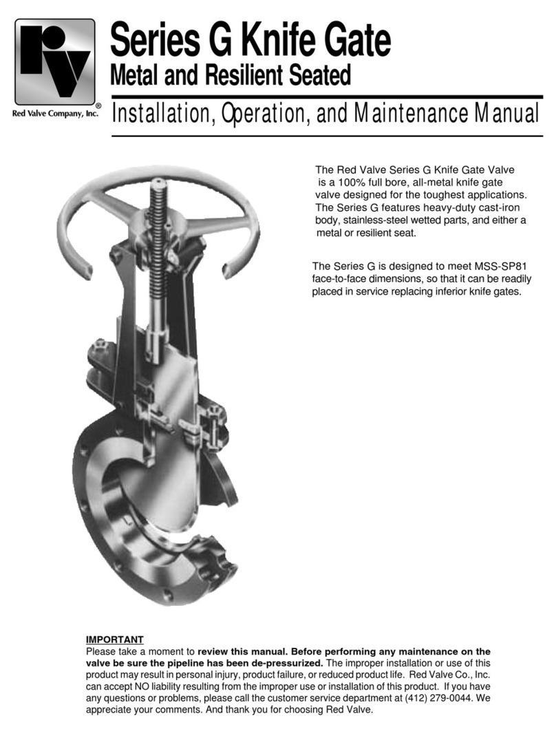
Red Valve G Series User manual

Red Valve

Red Valve G Series User manual

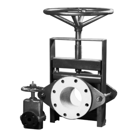
Red Valve 2600 Series User manual

Red Valve

Red Valve 2600 Series User manual

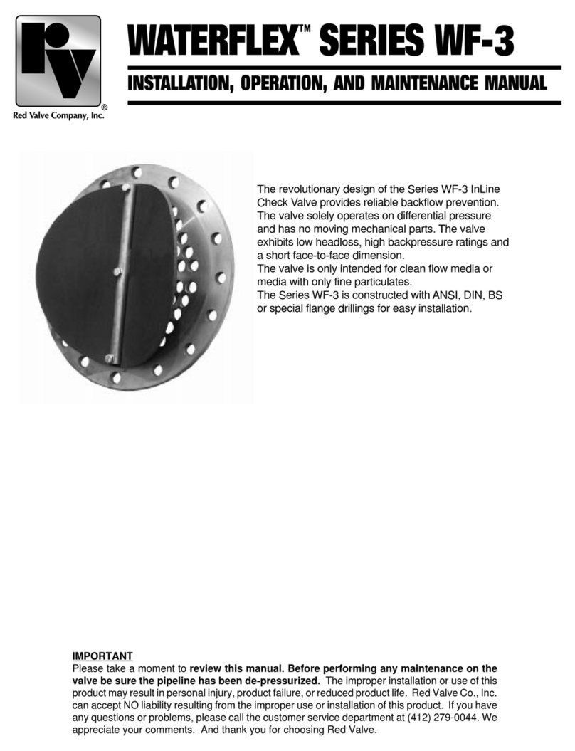
Red Valve WATERFLEX SERIES WF-3 Installation and operating instructions

Red Valve

Red Valve WATERFLEX SERIES WF-3 Installation and operating instructions

Red Valve Tideflex Series User manual

Red Valve

Red Valve Tideflex Series User manual

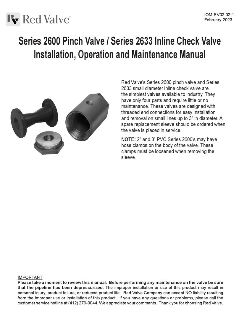
Red Valve 75 Series User manual

Red Valve

Red Valve 75 Series User manual

Red Valve Flexgate D series User manual

Red Valve

Red Valve Flexgate D series User manual

Popular Control Unit manuals by other brands

Aqua Medic Refill System 2.0 Operation manual

Aqua Medic

Aqua Medic Refill System 2.0 Operation manual

Rockwell Automation ControlLogix 1756-EN2TR installation instructions

Rockwell Automation

Rockwell Automation ControlLogix 1756-EN2TR installation instructions

ICP DAS USA tM-AD8C quick start guide

ICP DAS USA

ICP DAS USA tM-AD8C quick start guide

APS EPM205-MRS Technical reference

APS

APS EPM205-MRS Technical reference

HEIDENHAIN TNC 620 Programming Station user manual

HEIDENHAIN

HEIDENHAIN TNC 620 Programming Station user manual

resideo BA295S installation instructions

resideo

resideo BA295S installation instructions

ARMTEL TOP-EC-IP2 user manual

ARMTEL

ARMTEL TOP-EC-IP2 user manual

Ebyte E22-400M22S user manual

Ebyte

Ebyte E22-400M22S user manual

Parker PSUP Series installation manual

Parker

Parker PSUP Series installation manual

CLA-VAL 90G-21 Installation, operation & maintenance manual

CLA-VAL

CLA-VAL 90G-21 Installation, operation & maintenance manual

Eurolube 53402 manual

Eurolube

Eurolube 53402 manual

Pickering 40-518A user manual

Pickering

Pickering 40-518A user manual

Gema OptiMove CR07 Operating instructions and spare parts list

Gema

Gema OptiMove CR07 Operating instructions and spare parts list

RJG Lynx IA1-S-VI-24 product manual

RJG

RJG Lynx IA1-S-VI-24 product manual

Accutrol ACCUVALVE AVC6000 Installation & operation manual

Accutrol

Accutrol ACCUVALVE AVC6000 Installation & operation manual

Afag RM 63 Assembly and operating instructions

Afag

Afag RM 63 Assembly and operating instructions

TimeLine Lynx Keyboard Control Unit operating manual

TimeLine

TimeLine Lynx Keyboard Control Unit operating manual

Kontron AM4150 user guide

Kontron

Kontron AM4150 user guide

manuals.online logo
manuals.online logoBrands
  • About & Mission
  • Contact us
  • Privacy Policy
  • Terms and Conditions

Copyright 2025 Manuals.Online. All Rights Reserved.