Redback A 4574A User manual

Redback® A 4574A Alert/Evac/Chime Tone Generator
www.redbackaudio.com.au Redback® Proudly Made In Australia 1
Redback® A 4574A Alert/Evac/Chime Tone Generator
Operating Manual
A 4574A ALERT/EVAC/CHIME TONE GENERATOR
A 2078B Alert/Evac/Cancel Remote Wallplate
A 2081 Alert/Evac/Chime/Cancel Remote Wallplate
IMPORTANT NOTE:
Please read these instructions carefully from front to back prior to installation.
They include important setup instructions.
Failure to follow these instructions may prevent the unit from working as designed.
Distributed by Altronic Distributors Pty. Ltd.
Phone: 1300 780 999 Fax: 1300 790 999 Internet: www.altronics.com.au
Optional Accessories
A 2078B Alert/Evac/Chime Plate A 2081 Al/Ev/Chime/Cancel Plate
User manual revision number: 1.0 20/06/2023

www.redbackaudio.com.auRedback® Proudly Made In Australia2
Redback® A 4574A Alert/Evac/Chime Tone Generator
1.0 Overview
This unit has provision for playback of Alert, Evacuation and chime tones as well as an alert and/or emergency message.
When connected to a paging system amplier, building occupants can be alerted and/or evacuated in the event of an
emergency e.g.: re, gas leak, bomb scare, earthquake.
The Alert, Evacuation, Bell, and Emergency Messages are all MP3 based and stored on a Micro SD card which is accessible
from the front of the unit. The Alert, Evacuation and bell tones and cancel function are triggered by the front switches, or
by the rear terminal contacts for remote activation i.e. a clock, remote switch or optional A 2078B and A 2081 remote wall
plates.
It features 24V DC switched outputs which are enabled when the Alert, Evac or Chime tones are triggered. It is powered
from a 24V DC source (plugpack supplied) and features a line out facility and MP3 based Message Voice Over.
2.0 Features
3.0 Front Panel Guide
The layout of the A 4574A front panel is shown below in gure 1.
Fig 1.
1 Alert Tone Activation Switch
This switch is used to activate the Alert tone. Press for 2 seconds to activate.
2 Evac Tone Activation Switch
This switch is used to activate the Evacuation tone. Press for 2 seconds to activate.
3 Bell Tone Activation Switch
This switch is used to activate the Bell tone.
4 Cancel Tone Activation Switch
This switch is used to cancel the Alert, Evac or Bell tones. Press for 2 seconds to activate.
5 Micro SD Card
This is used to store the MP3 audio les for the Alert, Evac, Bell and Message playback.
6 Fault Indicator
This LED will illuminate when the unit has trouble reading an MP3 le or if les are missing from the Micro SD card..
7 On Indicator
This LED indicates the unit has power.
8 Standby Switch
When the unit is in standby mode this switch will illuminate. Press this button to switch the unit ON. Once the unit is ON the
On indicator will illuminate. Press this switch again to put the unit back in standby mode.
Timer
Evac Tone Generator
A 4574A
Standby
Micro
SD Card
Power/
EvacAlert Bell Cancel
Hold for 2 seconds Hold for 2 seconds Hold for 2 seconds
Fault On
1 2 3 4 5 6 7 8
• Level controls for alert/evac, bell and voice over
• Front panel alert/evac/bell and cancel switches
• All tones MP3 based
• Alert/Evac Emergency tones can be congured for
momentary or continuous operation
• 1U half rack cabinet
• Alert and Evac Tones conform to AS 1670.4
(Library included on Micro SD card)
• Compatible with re indicator boards & break glass
alarms
• Remote operation of alert , evac, bell tones & cancel.
• Local operation of alert, evac and bell
• MP3 based Alert and Evacuation Voice over message
facility
• Bell chime facility
• Switched 24V DC outputs for override relays or strobes
(outputs limited to 120mA)
• On-board timer for remote alert activation adjustable
from 30secs to 7.5min in 30 second increments. Switches
from alert to evac after preset time.
• Auxiliary level output
• 10 year warranty
• Australian designed and manufactured

Redback® A 4574A Alert/Evac/Chime Tone Generator
www.redbackaudio.com.au Redback® Proudly Made In Australia 3
Redback® A 4574A Alert/Evac/Chime Tone Generator
4.0 Rear Panel Guide
The layout of the A 4574A rear panel is shown below in gure 2.
Fig 2.
1 24V DC input
Connects to a 24V DC Plugpack with 2.1mm Jack.
2 24V DC Input (Backup)
Connects to a 24V DC backup supply with at least 1 amp current capacity. (Please observe the polarity)
3 RJ45 interface
This RJ45 port is for connection to future peripherals.
4 Dip Switches
These are used to select various options. Refer to DIP Switch Settings section 7.0.
5 Contacts
These contacts are for remote triggering of the Alert, Evac, Bell and cancel functions. These could be triggered by
a remote switch or any other closing contact.
6 24V DC Switched Outputs (Limited to 120mA current draw)
Switched 24V Out
This is a common 24V DC output which is activated when any of the Bell, Alert or Evac tones are triggered. The
terminals provided can be used for “Normal” or “Failsafe” modes (see section 8.0 for more details).
Evac 24V Out
This is a 24V DC output which is activated when the Evac tone is activated. The terminals provided can be used
for “Normal” or “Failsafe” modes (see section 8.0 for more details).
Alert 24V Out
This is a 24V DC output which is activated when the Alert tone is activated. The terminals provided can be used
for “Normal” or “Failsafe” modes (see section 8.0 for more details).
Bell 24V Out
This is a 24V DC output which is activated when the Bell tone is activated. The
terminals provided can be used for “Normal” or “Failsafe” modes (see section 8.0 for more details).
7 Alert/Evac Volume
Adjust this trimpot to adjust the Alert and Evacuation tones playback volume.
8 Bell Volume
Adjust this trimpot to adjust the Bell playback volume.
9 Voice-over Volume
Adjust this trimpot to adjust the message playback volume.
10 Audio Out RCA Connectors
Connect these outputs to the input of the PA amplier.
L
R
Audio
Out
24V
DC IN
www.redbackaudio.com.au
Manufactured in Australia
By Altronic Distributors Pty. Ltd.
1 2 3 4 5 6 7 8
DIP
Switch
Settings
DIP Switches
+
-
Volume
Bell Voice
Over
Alert/
Evac
50101010101010101
60011001100110011
70000111100001111
80000000011111111
Delay
(Sec.)
OFF
30
60
90
120
150
180
210
240
270
300
330
360
390
420
450
AUTO ALERT TO EVAC SWITCHOVER TIMER SETTINGS. 0 = OFF. 1 = ON.
SW
+_
24V
DC In
Bell
Alert
Cancel
Evac
Contacts
N/O
GND
N/C
Switched
N/O
GND
N/C
N/O
GND
N/C
N/O
GND
N/C
24V Outputs (Outputs limited to 120mA)
Evac Alert Bell
Interface
1 2 3 4 5 6 7 8
ON
4
Momentary operation
of Alert & Evac contacts
Bell - Repeatedly plays until
Not Used
OFF
1
2Bell - Plays Once after
SW
3
Continuous operation
of Alert & Evac contacts
Not Used
Activation Cancel Activated
1234 5 6 7 8 9 10

www.redbackaudio.com.auRedback® Proudly Made In Australia4
Redback® A 4574A Alert/Evac/Chime Tone Generator
5.0 Alert, Evac and Bell switches
The Alert, Evac and Bell switches on the front of the unit all work in momentary mode. ie. The alert tone will continue to
sound after the alert switch is momentarily pressed and the evac tone will continue to sound after the evac switch is mo-
mentarily pressed. Note: There is no automatic alert to evac switch-over option associated with the front panel switches.
Note 1: The tone that is being sounded (ie alert, evac, bell) will be indicated by the illumination of the relevant front panel
indicator.
Note 2: To cancel a tone either use the remote cancel contacts or the front cancel button. Note the cancel button will need
to be depressed for 2 seconds. This is to prevent accidental cancelling of a tone.
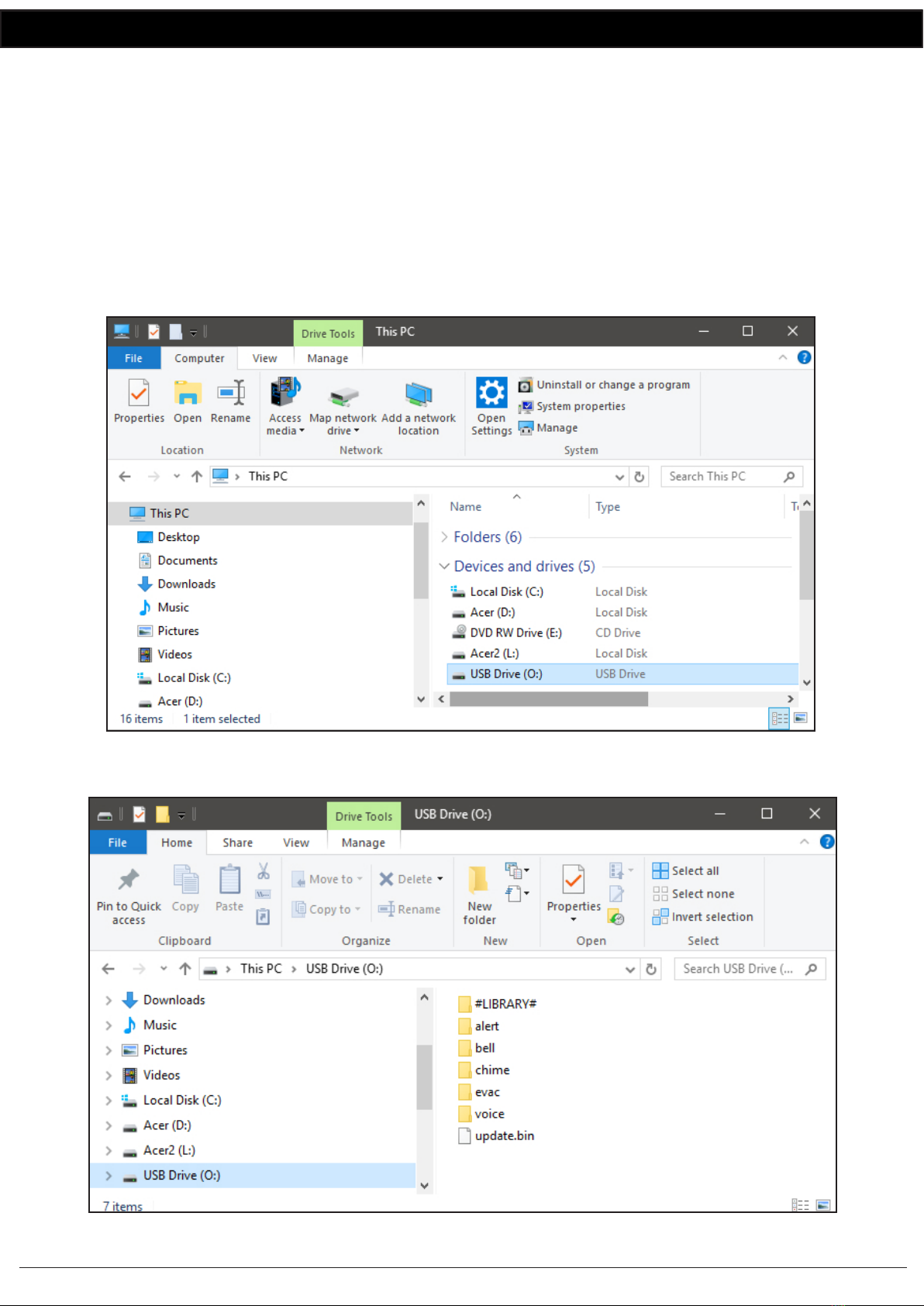
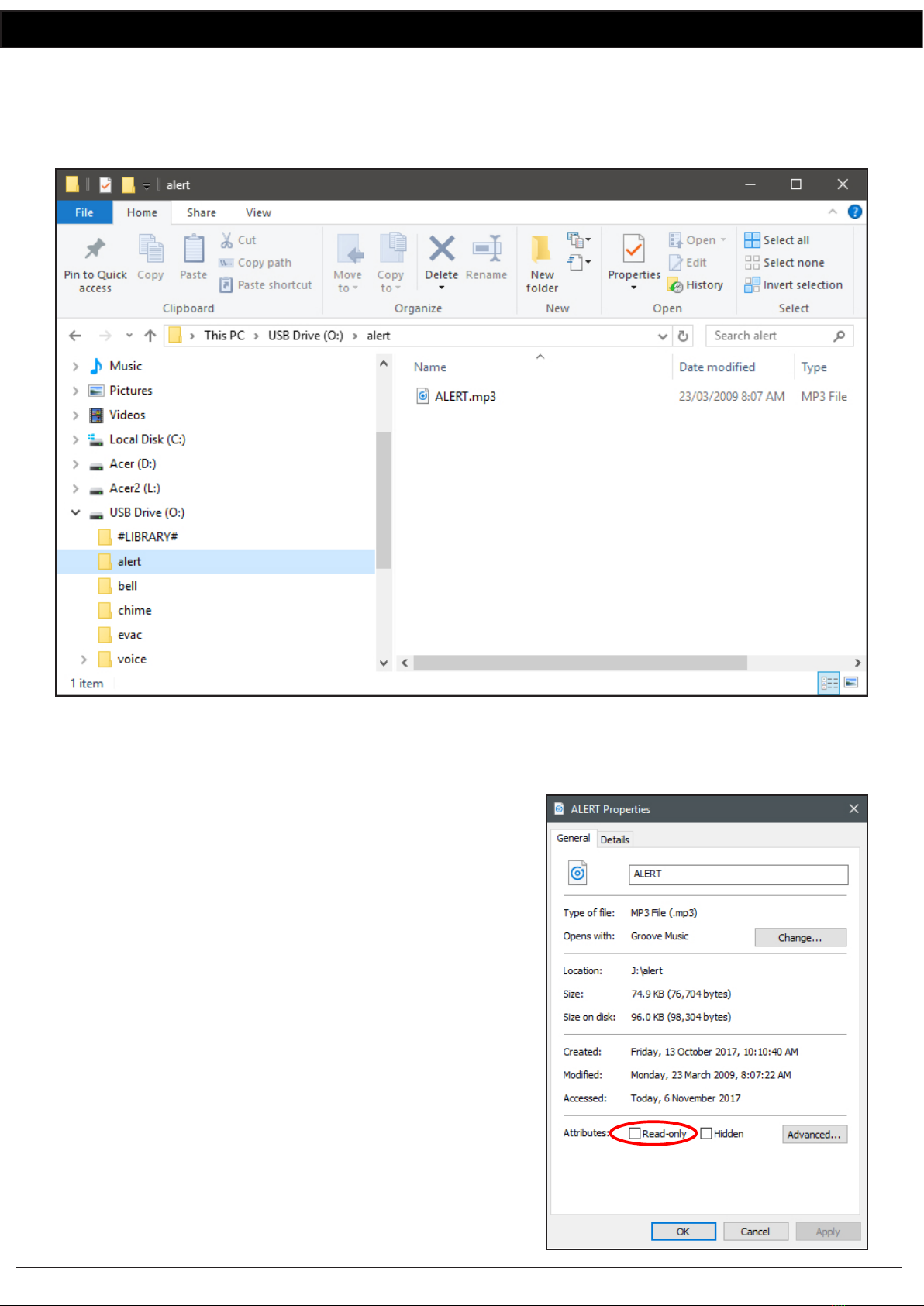
The Alert, Evac and Bell tones are stored on the supplied SD card. Separate folders are supplied on the SD card for each tone.
It is up to the user to provide the MP3 les (they must be in MP3 format) for each of the tones. A library of sample MP3 les
is supplied (in the #LIBRARY# folder). See section 11.0 for more details.
NOTE: The Fault LED will ash if any of the folders on the SD card are left empty. I.e. the Alert, Evac or Bell must all have an
MP3 le inside.
Once these Alert, Evac and Bell outputs are activated, the corresponding 24V switched outputs will become active (refer to
section 8.0 for more details).
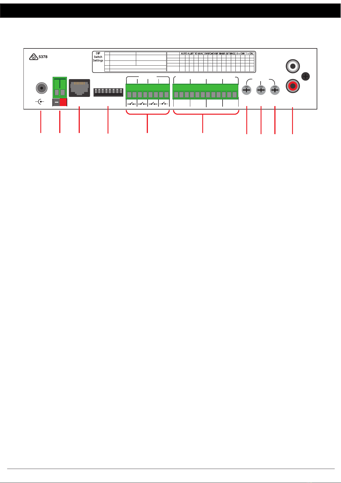
6.0 Remote Contacts (Rear of unit)
Provision has been made for four remote contacts on the back of the unit. These are all activated by closing the correspond-
ing contact (connecting the terminals together).
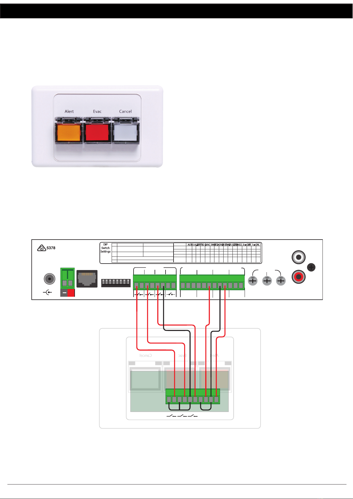
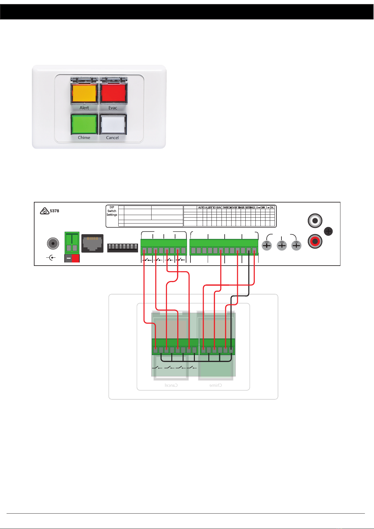
The alert, evac, bell and cancel remote contacts can be triggered with any sort of closing contact such as a timer to trigger
the bell, a remote switch or optional A 2078B and A 2081 remote wall plates (se section 12.0 for A 2078B and A 2081
wiring details).
Alert contact: These contacts are for remote triggering of the alert tone ie: for use with Fire Indicator Boards, break glass
alarms etc. These contacts can be set to either continuous or momentary operation via dip switch 1. ( refer to secton 7.0).
In continuous mode the alert tone will continue while the alert contact is triggered.
In momentary mode the alert tone will continue to sound after a momentary trigger of the alert contact.
Evac Contact: These contacts are for remote triggering of the evac tone. Connecting these terminals together will activate
the evac tone. These contacts can be set to either continuous or momentary operation via dip switch1. ( refer to secton 7.0).
In continuous mode the evacuation tone will continue while the evac contact is triggered.
In momentary mode the evacuation tone will continue to sound after a momentary trigger of the evac contact.
Bell Chime Contacts: These contacts are for remote triggering of the bell chime sound. This bell chime can be used for
signalling lunch breaks, start of classes, and can be triggered from a time clock or similar device.
Cancel contact: These contacts are for remote cancelling of the alert or evac tones.
7.0 Dip Switch Settings
The A 4574A has various options which are set by the DIP switches on the rear of the unit which are outlined below.
Switch 1: The Alert and Evac contacts can be set to either continuous or momentary operation.
In continuous mode the alert/evac tone will continue while the corresponding rear contact is triggered.
In momentary mode the alert/evac tone will continue to sound after a momentary trigger of the rear contact.
1 - OFF: continuous operation of alert/evac contacts
1 - ON: momentary operation of alert/evac contacts
Switch 2: This switch is used to either loop the Bell, or play the Bell only once after it has
been triggered.
2 - OFF: Bell MP3 will play once
2 - ON: Bell MP3 loops
Switches 5 - 8 Evacuation Timer Settings:
These switches control the time period before the unit switches from the alert, to the evac
tone when the Alert is triggered by the rear contact. This time period can be switched from
30s to 7.5 minutes in 30s increments. Factory preset is 30s.
Note: Setting all switches 5 - 8 to OFF deactivates the switchover function.
IMPORTANT NOTE:
Ensure power is switched off when adjusting DIP switches.
New settings will be effective when power is switched back on.
5 6 7 8

Redback® A 4574A Alert/Evac/Chime Tone Generator
www.redbackaudio.com.au Redback® Proudly Made In Australia 5
Redback® A 4574A Alert/Evac/Chime Tone Generator
8.0 24V OUTPUT CONNECTIONS
The A 4574A is tted with four sets of 24V switched outputs for driving external devices such as strobes, sirens and atten-
uators. Each output has a maximum current draw of 120mA. When connecting devices which require more than 24V DC
@ 120mA then an external supply and relays will be required.
In the illustration of gure 3 a high current school bell is to be activated by the Bell 24V switched output. As the current
draw of the Bell is more than 120mA, a relay board is used to switch an external power supply. The Altronics S 4444 24V
Relay Board as shown is an inexpensive and easily installed option designed for this purpose. 24V DC strobes such as the
Altronics S 5423, S 5430 and S 5435 strobes also draw more than 120mA so they are connected in the same fashion as
shown in gure 3.
Switched 24V Out:
These contacts are for connection of override relays in remote volume controls. An override relay is necessary where
attenuators are used so that the alert tone, evac tone or message is broadcast at full volume regardless of the volume
setting on the individual volume control (attenuator).
The override relay can be set to “NORMAL” mode when connection is made between the N/O (normally open) contact
and the GND connection. In this conguration 24V appears when any of the alert tone, evac tone, voice over message or
paging functions are activated.
The override relay can be set to “FAILSAFE” mode when connection is made between the N/C (normally closed) contact
and the GND connection. In this conguration 24V is removed when any of the alert tone, evac tone, voice over message
or paging functions are activated.
Alert 24V Out:
These contacts are for switched 24V outputs whenever the alert tones is activated. This may be used to run external
systems such as strobes in unusually noisy environments. These operate in the same manner as the switched 24V out
contacts i.e. connection between the N/O contact and the GND contact will operate in NORMAL mode and connection
between the N/C contact and the GND will operate in FAILSAFE mode.
Evac 24V Out:
These contacts are for switched 24V outputs whenever the evac tones is activated. This may be used to run external
systems such as strobes in unusually noisy environments. These operate in the same manner as the switched 24V out
contacts i.e. connection between the N/O contact and the GND contact will operate in NORMAL mode and connection
between the N/C contact and the GND will operate in FAILSAFE mode.
Bell 24V Out:
These contacts are for operating an external relay used to operate something like a lunch bell etc.
These operate in the same manner as the switched 24V out contacts i.e.: connection between the N/O contact and the
GND contact will operate in NORMAL mode and connection between the N/C contact and GND will operate in FAILSAFE
mode.
Fig 3.
L
R
Audio
Out
24V
DC IN
www.redbackaudio.com.au
Manufactured in Australia
By Altronic Distributors Pty. Ltd.
1 2 3 4 5 6 7 8
DIP
Switch
Settings
DIP Switches
+-
Volume
Bell Voice
Over
Alert/
Evac
50101010101010101
60011001100110011
70000111100001111
80000000011111111
Delay
(Sec.)
OFF
30
60
90
120
150
180
210
240
270
300
330
360
390
420
450
AUTO ALERT TO EVAC SWITCHOVER TIMER SETTINGS. 0 = OFF. 1 = ON.
SW
+_
24V
DC In
Bell
Alert
Cancel
Evac
Contacts
N/O
GND
N/C
Switched
N/O
GND
N/C
N/O
GND
N/C
N/O
GND
N/C
24V Outputs (Outputs limited to 120mA)
Evac Alert Bell
Interface
1 2 3 4 5 6 7 8
ON
4
Momentary operation
of Alert & Evac contacts
Bell - Repeatedly plays until
Not Used
OFF
1
2Bell - Plays Once after
SW
3
Continuous operation
of Alert & Evac contacts
Not Used
Activation Cancel Activated
Attenuator tted
with over ride relay.
(such as Altronics A 2260A)
24V Strobes for
visual warning
(such as Altronics
S 5430 and S 5435)
24V Bell
(eg school bell, lunch bell etc)
+24V
GND
24V Relay Board
(Altronics S 4444)
N/C1
N/C2
N/O2
N/O1
COM1
COM2
External
24V DC Supply
+24V
GND
+24V
GND
24V Relay Board
(Altronics S 4444)
N/C1
N/C2
N/O2
N/O1
COM1
COM2
External
24V DC Supply
+24V
GND

www.redbackaudio.com.auRedback® Proudly Made In Australia6
Redback® A 4574A Alert/Evac/Chime Tone Generator
9.0 MP3 AUDIO FILES and ALERT and EVAC VOICE OVER MESSAGES
The supplied MIcro SD card houses all the MP3 audio les used for the output tones. These les are stored in six separate
folders (see gure 4) and relate to the corresponding output. e.g. the Alert folder houses the MP3 le to be played when
the Alert mode is triggered.
These les can be any length and bit rate, but must be in MP3 format (they cannot be Wav les or AAC les).
(NOTE: only one MP3 le can be in each folder).
There is also a folder labelled “#LIBRARY# which contains a host of sample MP3 les.
The “Voice” folder contains the MP3 audio les played as the Alert and Evacuation messages. There are separate folders
for both the Alert and Evac messages as shown in gure 4.
The messages have to be recordered in MP3 format using any readily available PC software or other means, and then
transferred to these folders.
Fig 4.
10.0 Activating the Voice Over Message:
Voice over messages become active when an MP3 le is present in the relevant folder.
If the voice over message is not required leave the folder empty.

Redback® A 4574A Alert/Evac/Chime Tone Generator
www.redbackaudio.com.au Redback® Proudly Made In Australia 7
Redback® A 4574A Alert/Evac/Chime Tone Generator
11.0 Installing MP3 Files
You will rst need to remove power from the A 4574A then remove the Micro SD card from the front of the unit.
To remove the Micro SD card, push the card in and it will eject itself.
In order to access the program, the Micro SD card will need to be connected to a PC. You will need a PC or laptop equipped
with a Micro SD card reader to do this. If a Micro SD slot is not available then the Altronics D 0371A USB Memory Card
Reader or similar would be suitable (not supplied).
Step by step guide to installing an MP3 onto the MIcro SD card with a Windows installed PC
Make sure the PC is on and card reader connected and correctly installed. Then insert the Micro SD card into the reader.
Go to “My Computer” or “This PC” and open the Micro SD card which is usually marked “Removable disk”or “USB
Drive”.
In this case it is named “USB Drive (O:) as shown in gure 5.
Fig 5
Open the USB Drive and you should get a window that looks like gure 6.
Fig 6

www.redbackaudio.com.auRedback® Proudly Made In Australia8
Redback® A 4574A Alert/Evac/Chime Tone Generator
The contents of the Micro SD Card include a Library folder of sample MP3 les and ve folders for the MP3 les associated
with the various functions of the A 4574A.
There should be default MP3 les included in each folder. These will need to be replaced with your own MP3 les.
Open the folder in which you want to install an MP3 (in our case its the Alert folder) and you should see an MP3 le which
is named Alert.MP3 as shown in gure 7.
Fig 7.
This MP3 le needs to be deleted and replaced by the MP3 le you want to play when you activate the Alert mode. The
MP3 le name is not important. But it is important that there is only one MP3 le in the Alert folder.
Check the properties of the MP3 le.
NOTE the new MP3 le cannot be “Read only”.
To check this, right click on the MP3 le and scroll down and select
Properties, you will get a window that looks like gure 8.
Make sure the “Read Only” box has no tick in it.
The new MP3 is now installed on the card. Repeat these steps for the
other MP3 folders if you need to.
Step 7: The card can be removed from the PC following windows safe
card removal procedures. Make sure the A 4574A is OFF and insert the
Micro SD card into the slot in the front; it will click when fully inserted.
The A 4574A is ready to use.
Fig 8

Redback® A 4574A Alert/Evac/Chime Tone Generator
www.redbackaudio.com.au Redback® Proudly Made In Australia 9
Redback® A 4574A Alert/Evac/Chime Tone Generator
12.0 Optional Remote Wall Plates
There are two optional remote wall plates which can be connected to the A 4574A for remote triggering of the Alert,
Evacuation and Bell tones and for remotely cancelling any tones which may be active.
12.1 A 2078B Remote Plate
The A 2078B wall plate provides a remote means of trigger-
ing the Alert and Evacuation tones and the cancel function.
Connection is made to the A 4574A via a minimum of 7
wires as shown in Fig 9.
If standard Cat5 cable is used for the wiring, the plate can
be located up to 30m away from the main unit. This can be
increased to 100m away using heavier guage cable, which
reduces the voltage drop across this distance and ensures the
switch LEDs illuminate.
The Alert/Evac/Cancel switches on the A 2078B wall plate are
connected to the corresponding contacts on the rear of the
A 4574A. While the Alert and Evac LEDs on the wall plate
are connected to the Alert 24V and Evac 24V outputs of the
A 4574A. The cancel LED is not connected. A mimimum of
seven wires can be used if the ground connections of the
Alert and Evac 24V outputs are linked and if the Alert/Evac
and cancel switch grounds are linked together (see Fig 9).
Fig 9
A 4574 REAR PANEL
L
R
Audio
Out
24V
DC IN
www.redbackaudio.com.au
Manufactured in Australia
By Altronic Distributors Pty. Ltd.
1 2 3 4 5 6 7 8
DIP
Switch
Settings
DIP Switches
+
-
Volume
Bell Voice
Over
Alert/
Evac
50101010101010101
60011001100110011
70000111100001111
80000000011111111
Delay
(Sec.)
OFF
30
60
90
120
150
180
210
240
270
300
330
360
390
420
450
AUTO ALERT TO EVAC SWITCHOVER TIMER SETTINGS. 0 = OFF. 1 = ON.
SW
+_
24V
DC In
Bell
Alert
Cancel
Evac
Contacts
N/O
GND
N/C
Switched
N/O
GND
N/C
N/O
GND
N/C
N/O
GND
N/C
24V Outputs (Outputs limited to 120mA)
Evac Alert Bell
Interface
1 2 3 4 5 6 7 8
ON
4
Momentary operation
of Alert & Evac contacts
Bell - Repeatedly plays until
Not Used
OFF
1
2Bell - Plays Once after
SW
3
Continuous operation
of Alert & Evac contacts
Not Used
Activation Cancel Activated
Cancel
Switch
Evac
Switch
Alert
Switch
Alert
Lamp
Evac
Lamp
- + - +
Evac CancelAlert
A 2078B REMOTE WALL PLATE

www.redbackaudio.com.auRedback® Proudly Made In Australia10
Redback® A 4574A Alert/Evac/Chime Tone Generator
12.2 A 2081 Remote Plate
The A 2081 wall plate provides a remote means of triggering the Alert, Evacuation and Bell tones and the cancel function.
Connection is made to the A 4574A via a minimum of 8 wires as
shown in Fig 10. If light duty cable is used for the wiring (such as
Cat5e/6 cable), the plate can be located up to 30m away from
the main unit. This can be increased to 100m away using heavier
guage cable, which reduces the voltage drop across this distance
and ensures the switch LED’s illuminate.
The Alert/Evac/Chime/Cancel switches on the A 2081 wall plate
are connected to the corresponding contacts on the rear of the
A 4574A. While the Alert, Evac and Bell LEDs on the wall plate
are connected to the Alert, Evac and Bell 24V outputs of the A
4574A. The cancel LED is not connected. A mimimum of eight
wires can be used if the ground connections of the Alert, Evac
and Bell 24V outputs and the grounds of the Alert/Evac/Chime
and cancel switches are linked together (see Fig 10).
Fig 10
13.0 Troubleshooting
Evac
Alert
Chime Cancel
A 4574 REAR PANEL
L
R
Audio
Out
24V
DC IN
www.redbackaudio.com.au
Manufactured in Australia
By Altronic Distributors Pty. Ltd.
1 2 3 4 5 6 7 8
DIP
Switch
Settings
DIP Switches
+-
Volume
Bell Voice
Over
Alert/
Evac
50101010101010101
60011001100110011
70000111100001111
80000000011111111
Delay
(Sec.)
OFF
30
60
90
120
150
180
210
240
270
300
330
360
390
420
450
AUTO ALERT TO EVAC SWITCHOVER TIMER SETTINGS. 0 = OFF. 1 = ON.
SW
+_
24V
DC In
Bell
Alert
Cancel
Evac
Contacts
N/O
GND
N/C
Switched
N/O
GND
N/C
N/O
GND
N/C
N/O
GND
N/C
24V Outputs (Outputs limited to 120mA)
Evac Alert Bell
Interface
1 2 3 4 5 6 7 8
ON
4
Momentary operation
of Alert & Evac contacts
Bell - Repeatedly plays until
Not Used
OFF
1
2Bell - Plays Once after
SW
3
Continuous operation
of Alert & Evac contacts
Not Used
Activation Cancel Activated
Alert
Switch
- +- +
Chime
Switch
Evac
Switch
Alert
Lamp
Evac
Lamp
Cancel
Switch
A 2081 REMOTE WALL PLATE
- +
Chime
Lamp
- + - + - + - +

Redback® A 4574A Alert/Evac/Chime Tone Generator
www.redbackaudio.com.au Redback® Proudly Made In Australia 11
Redback® A 4574A Alert/Evac/Chime Tone Generator
14.0 Firmware Update
It is possible to update the rmware for this unit by downloading updated versions from www.altronics.com.au or
redbackaudio.com.au.
To perform an update, follow these steps.
1) Download the Zip le from the website.
2) Remove the Micro SD card from the A 4574A and insert it into your PC. (Follow the steps on page 6 to open the SD
card).
3) Extract the contents of the Zip le to the root folder of the SD Card.
4) Rename the extracted .BIN le to update.BIN.
5) Remove the SD card from the PC following windows safe card removal procedures.
6) With the power turned OFF, insert the Micro SD card back into the A 4574A.
7) Turn the A 4574A ON. The unit will check the Micro SD card and if an update is required the A 4574A will perform the
update automatically.
15.0 Specications
SYMPTOMS REMEDIES
Fault LED ashes Make sure the Alert, Evac and Bell folders on the Micro SD
card have MP3 les in them.
MP3 Audio les not playing. Make sure they are in MP3 format. Make sure Micro SD
card inserted properly. Check MP3 is installed in appropri-
ate folder.
Alert/evac tone levels are low. Adjust Evac volume on rear of unit.
Bell volume is low Adjust Bell volume on rear of unit.
Unit will not play MP3 les or Fault LED ashes. Make sure all MP3 les are not “Read Only”. See page 8.
Power switch is illuminated Red but unit doesn’t work The unit is in standby mode. Press the Power/Standby
switch. The unit is ON when the Blue ON LED is illuminat-
ed.
Alert or Evac message not playing. Check MP3 is installed in a voice folder.
DIP switch changes not effective. Turn the unit OFF before changing DIP switch settings.
Settings become effective after power is returned.
I don’t know how to record a message. This unit does not have a recording facility. A message MP3
will have to be recorded on a PC or some other equip-
ment.
24V DC outputs stop working. These outputs are limited to 120mA output and will trip
the internal fuse when overloaded. They will reset once
they have cooled down.

www.redbackaudio.com.auRedback® Proudly Made In Australia12
Redback® A 4574A Alert/Evac/Chime Tone Generator
All Australian made Redback products are covered by a 10 year warranty.
Should a product become faulty please contact us to obtain a return authorisation number. Please ensure you have all the
relevant documentation on hand. We do not accept unauthorised returns. Proof of purchase is required so please retain
your invoice.
Distributed by Altronic Distributors Pty. Ltd. Perth. Western Australia.
Phone: 1300 780 999 Fax: 1300 790 999 Internet: www.altronics.com.au
* Specications subject to change without notice
OUTPUT LEVEL:...........................................................0dBm
DISTORTION:..............................................................0.01%
FREQ. RESPONSE:.........................................140Hz - 20kHz
SIGNAL TO NOISE RATIO:
Alert/Evac/Chime:.............................-70dB typically
OUTPUT CONNECTORS:
Audio Output:............................RCA Stereo Socket
Switched 24V DC Out:...................Screw Terminals
Alert 24V DC Out :........................ Screw Terminals
Evac 24V DC Out:...........................Screw Terminals
Bell 24V DC Out:............................Screw Terminals
PLEASE NOTE: Output loads limited to 120mA.
INPUT CONNECTORS:
24V DC Power:...............................Screw Terminals
24V DC Power:...........................2.1mm DC Socket
Remote Alert,Evac,Bell,Cancel:.......Screw Terminals
AUDIO STORAGE:
Micro SD Card: ......................................Max 16GB
CONTROLS:
Bell, Alert/EvacTones:...........................Rear Volume
Voice over.:.........................................Rear Volume
Power:..............................................On/Off Switch
Alert Switch:.......................Illuminated Push Switch
Evac Switch:.......................Illuminated Push Switch
Bell Switch:.........................Illuminated Push Switch
Cancel Switch:......................................Push Switch
INDICATORS:........................................................Power on
........................................................ Fault
POWER SUPPLY: ...................................... 24V DC @ 1 Amp
DIMENSIONS:≈.................................... 210W x 122D x 44H
WEIGHT: ≈................................................................ 0.4 kg
COLOUR: ..................................................................Black
Table of contents
Other Redback Security System manuals