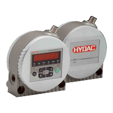
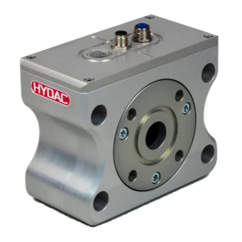
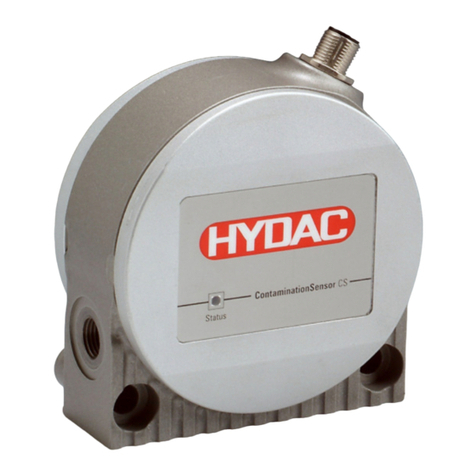
ContaminationSensor – CS 2000 series
HYDAC Filtertechnik GmbH en Page 3
BeWa CS2000 3117721e en.doc 2008-03-28
Contents
1General Safety Precautions ...........................................................................................9
1.1 Obligations and Liability.................................................................................................9
1.2 Explanation of Symbols and Warnings, etc. .................................................................. 9
1.2.1 Basic Symbols......................................................................................................10
1.3 Proper/Designated Use ...............................................................................................10
1.4 Improper Use...............................................................................................................10
1.5 Informal Safety Precautions ........................................................................................11
1.6 Training and Instruction of Personnel..........................................................................12
1.7 Safety measures to be followed in normal operation...................................................12
1.8 Electrical Hazards........................................................................................................12
1.9 Maintenance, Servicing and Troubleshooting .............................................................13
1.10Modifications to the CS................................................................................................13
1.11Cleaning the CS and Disposal of the Media and Agents Used ...................................13
2Packing, Transportation, Storage and Disposal ........................................................14
2.1 Transportation Packing................................................................................................14
2.2 Storage ........................................................................................................................14
2.2.1 Storage conditions................................................................................................14
2.3 Disposal / Recycling and Decommissioning................................................................14
3Scope of Delivery ..........................................................................................................15
4Technical Description of the CS ..................................................................................16
4.1 General data................................................................................................................16
4.2 CS Design ...................................................................................................................17
4.3 Restrictions pertaining to use ...................................................................................... 17
4.4 Hydraulic Schematic....................................................................................................17
4.4.1 Hydraulic schematic for pressure/viscosity ranges 1 and 2 .................................18
4.4.2 Hydraulic schematic for pressure/viscosity ranges 3 and 4 .................................18
4.4.3 Hydraulic schematic for CS 2xxx0........................................................................18
5Installation and Operation............................................................................................19
5.1 Electrical Installation....................................................................................................19
5.1.1 Terminal Assignment............................................................................................ 19
5.2 Electrical connection of the CS....................................................................................22
5.3 Selecting a measurement point ................................................................................... 22
5.4 Hydraulic connection of the CS ...................................................................................23
5.5 Removing the CS from the Hydraulic System .............................................................24
6Description of the Measuring Modes .......................................................................... 25
6.1 Mode M1: Measure......................................................................................................25
6.2 Mode M2: Measure and switch....................................................................................25
6.3 Mode M3: Filter until ....................................................................................................25
6.4 Mode M4: Filter from until............................................................................................25
6.5 Switching behavior of the relays:.................................................................................25
7Analog inputs ................................................................................................................29
7.1 Connection assignment AS 1000 series......................................................................29
