Procedure
Sensing output
setting
External input
setting
Measurement display
DOWN: Press for 3 seconds
UP / DOWN
UP / DOWN
UP / DOWN
UP / DOWN
UP / DOWN
UP / DOWN
UP / DOWN
UP / DOWN
UP / DOWN
UP /
DOWN
UP /
DOWN
UP /
DOWN
UP /
DOWN
UP /
DOWN
UP /
DOWN
UP /
DOWN
UP /
DOWN
UP /
DOWN
TEACH
TEACH
TEACH
TEACH
TEACH
TEACH
TEACH
TEACH
TEACH
UP /
DOWN
UP /
DOWN
UP /
DOWN
UP /
DOWN
UP /
DOWN
UP /
DOWN
UP /
DOWN
UP /
DOWN
UP /
DOWN
Response time
setting
Response time
setting
Timer setting
Hysteresis setting
Output operation
setting
Reset setting
Hold setting
ECO Setting
High precision
No timer
Zero set function
Normal sensing
mode
Hysteresis width
UP key : Increases hysteresis width
DOWN key : Decreases hysteresis width
Light-ON
Reset NG
Hold OFF
ECO OFF
Standard
OFF-delay
Teaching function
Dark-ON
Reset OK
Hold ON
ECO ON
High speed
ON-delay
Light emitting
stop function
Rising differen-
tial mode
One-shot
Trigger function
Trailing differen-
tial mode
UP / DOWN
UP /
DOWN
TEACH
UP /
DOWN
Display setting Normal Invert Offset
1-point teaching
Window com-
parator mode
2-point teaching
Window com-
parator mode
3-point teaching
Window com-
parator mode
13
ERROR INDICATION
●In case of errors, attempt the following measures.
Error indication Description Remedy
<Hold OFF>
<Hold ON>
Measured value blinks
Insufcientamountofreectedlight.
The sensing object is out of the sensing range.
Conrmthatthesensingdistanceiswithinthe
specicationrange.
Adjust the installation angle of the sensor.
Flash memory is damaged or passed its life expectancy.
Pleasecontactourofce.
Load of the sensing output is short-circuited
causinganover-currenttoow. Turn OFF the power and check the load.
The semiconductor laser is damaged or
passed its life expectancy. Pleasecontactourofce.
• Whenzeroset isset,the measurement is
not performed normally.
• Since the display setting is set to “Offset”,
thezerosetfunctioncannotbeused.
• Conrmthatthesensingdistanceiswithin
thespecicationrange.
•
Set the display to any setting except “Offset.”
During teaching, the measurement is not per-
formed normally. Conrmthatthesensingdistanceiswithinthe
specicationrange.
System error Pleasecontactourofce.
14
SPECIFICATIONS
Type
Measurement
center 30mm type Measurement
center 50mm type
Measurement cen-
ter 100mm type Measurement cen-
ter 200mm type Measurement cen-
ter 400mm type
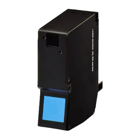
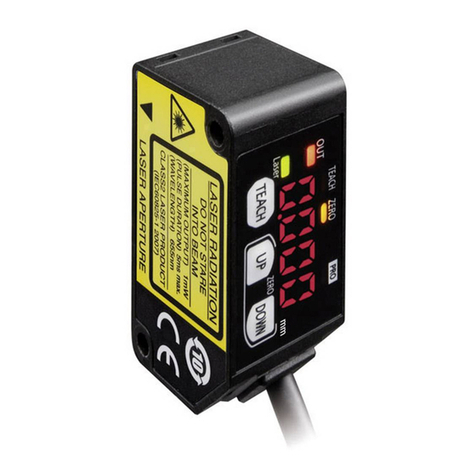
Model No. NPN output HG-C1030 HG-C1050 HG-C1100 HG-C1200 HG-C1400
PNP output HG-C1030-P HG-C1050-P HG-C1100-P HG-C1200-P HG-C1400-P
Measurement center
distance 30mm 50mm 100mm 200mm 400mm
Measurement range ±5mm ±15mm ±35mm ±80mm ±200mm
Repeatability 10μm 30μm 70μm 200μm
300μm(measurement
distance 200 to 400mm)
800μm(measurement
distance 400 to 600mm)
Linearity ±0.1%F.S. ±0.2%F.S.
±0.2%F.S. (measurement
distance 200 to 400mm)
±0.3%F.S. (measurement
distance 400 to 600mm)
Temperature characteristic 0.03%F.S./°C
Light source Red semiconductor laser Class 2 [JIS / IEC / GB / FDA (Note 2)]
Max. output: 1mW, Emission peak wavelength: 655nm
Beam diameter (Note 3) Approx.
ø50μm
Approx.
ø70μm
Approx.
ø120μm
Approx.
ø300μm
Approx.
ø500μm
Supply voltage 12 to 24V DC ±10%, Ripple P-P 10% or less
Power consumption 40mA or less (at 24V DC supply voltage), 60mA or less (at 12V DC supply voltage)
Control output
<NPN output type>
NPN open-collector transistor
• Maximum sink current: 50mA
• Applied voltage: 30V DC or less
(Between control output to 0V)
• Residual voltage: 1.5V or less
(At 50mA sink current)
• Leakage current: 0.1 mA or less
<PNP output type>
PNP open-collector transistor
• Maximum source current: 50mA
• Applied voltage: 30V DC or less
(Between control output to +V)
• Residual voltage: 1.5V or less
(At 50mA source current)
• Leakage current: 0.1 mA or less
Output operation Switchable either Light-ON or Dark-ON
Short-circuit protection Incorporated (Auto reset type)
Analogue output • Output range: 0 to 5V (at alarm: +5.2V)
• Outputimpedance:100Ω
Response time Switchable between 1.5ms / 5ms / 10ms
External input
<NPN output type>
NPN non-contact input
• Input conditions
Invalid: +8 to +V DC or Open
Valid: 0 to +1.2V DC
• Inputimpedance:Approx.10kΩ
<PNP output type>
PNP non-contact input
• Input conditions
Invalid: 0 to +0.6V DC or Open
Valid: +4 to +V DC
• Inputimpedance:Approx.10kΩ
Protection IP67 (IEC)
Degree of pollution 2
Ambient temperature -10 to +45°C (No dew condensation or icing allowed), Storage: -20 to +60°C
Ambient humidity 35 to 85% RH, Storage: 35 to 85% RH
Ambient illuminance Incandescentlamp:Acceptancesurfaceilluminance3,000ℓxorless
Operating altitude 2,000m or less
Cable 0.2mm25-core composite cable, 2m long
Material Enclosure: Aluminum die-cast, Front cover: Acrylic
Weight Approx. 35g (without cable), approx. 85g (including cable)
Applicable standard EMC Directive Compliance, FDA Standard
Notes: 1)
Supply voltage: 24V DC, ambient temperature: +20°C, response time: 10ms, and analogue output value of
measurementcenterdistanceareusedforunspeciedmeasurementconditions.Thesubjectiswhiteceramics.
2) This is based on the FDA Standard, according to Laser Notice No. 50 of the FDA Standard.
3)
Thisisthesizeinthemeasurementcenterdistance.Thesevaluesweredenedbyusing1/e
2
(approx. 13.5%)
ofthecenterlightintensity.Due toleaklightoutsidethespecied area, thereectancearoundthedetecting
point may be higher than at the point and this may affect the measurement value.
15
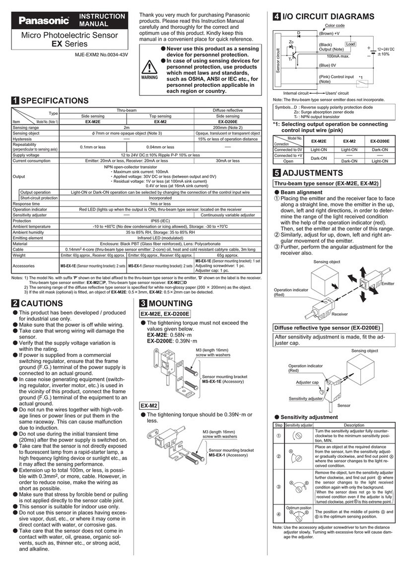
CAUTIONS
●This product has been developed / produced for industrial use only.
●Make sure that the power supply is OFF before starting the wiring.
●If the wiring is performed incorrectly, it will cause a failure.
●Do not run the wires together with high-voltage lines or power lines, or put them in
the same raceway. This can cause malfunction due to induction.
●Verify that the supply voltage variation is within the rating.
●If power is supplied from a commercial switching regulator, ensure that the frame
ground (F.G.) terminal of the power supply is connected to an actual ground.
●If noise generating devices (switching regulators, inverter motors, etc.) are used
around the sensor mounting area, make sure to connect the frame ground (FG)
terminal of the device.
●Do not use this product during the transient state when the power supply is turned
ON.
●The overall length of the cable can be extended to 10m maximum with a cable
sizeof0.3mm2or more.
●Make sure that stress by forcible bend or pulling is not applied to the sensor cable
joint.
●Although it depends on the type, light from rapid start type or high frequency
lightingtypeuorescentlights,sunlightandetc.mayaffectthesensing,therefore
make sure to prevent direct incident light.
●This product is suitable for indoor use only.
●Keep water, oil, fingerprints and etc. which reflect light, or dust, particles or etc.
which interrupts the light, away from the emitting / receiving surfaces of this product.
If contaminants adhere to the surface, wipe off with a dust-free soft cloth, or lens
cleaning paper.
●Do not use the sensor in locations where there is excessive vapor, dust or etc. or
in an atmosphere where corrosive gases, etc. is generated.
●Take care that the product does not come in contact with oil, grease, organic sol-
vents such as thinner, etc., strong acid or alkaline.
●Make sure to turn OFF the power supply, before cleaning the light emitting / re-
ceiving windows of the sensor head.
●There is a certain deviation in the directionality of this product. Install the product
usingamountingbracketorsimilarttingtoallowtheadjustmentofopticalaxis.
