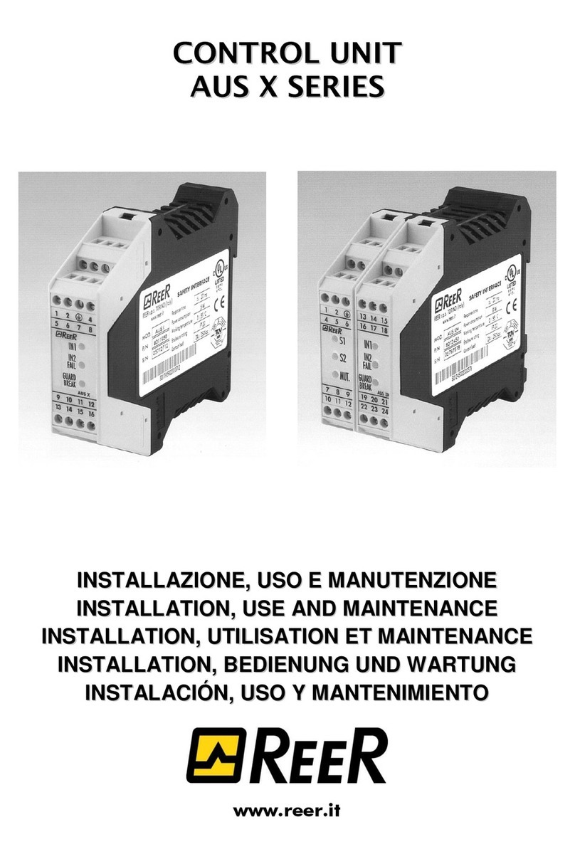
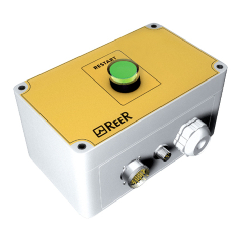
Reer ARGOLUX AU S-TWIN Quick start guide

ARGOLUX
AU S-TWIN
CONTROL
UNIT
INSTALLATION
AND USE
TABLE OF CONTENTSTABLE OF CONTENTS
GENERAL DESCRIPTION .......................................................................................2
OPERATING MODES.............................................................................................3
CONFIGURATION OF THE UNIT...........................................................................4
STATUS OF CONTACTS................................................................................5
INDICATOR LIGHTS .....................................................................................5
SPECIFICATIONS ..................................................................................................6
DIMENSIONS (distances in mm)............................................................................6
INSTALLATION AND ELECTRIC CONNECTIONS ....................................................7
CONNECTION DIAGRAMS...........................................................................9
TROUBLESHOOTING .................................................................................12
GUARANTEE.......................................................................................................13

2
GENERAL DESCRIPTION
The AU S-TWINAU S-TWIN control unit is a safety device that can be used to
interface the REER type 2 optoelectronic sensors with the machine control
system, thus achieving a type 2 electrosensitive safety system conforming
to IEC 61496-1/2.
Preservation of the protective function is guaranteed by means of a
functional test.
When the TEST command is actuated, a test routine is executed on all the
AU S-TWIN internal circuits and associated sensors.
Only a positive test result will enable closing of the AU S-TWIN control
unit internal safety relays, while detection of a dangerous fault will result in
the immediate opening of these.
This manual provides detailed instructions as regards operation and
configuration of the AU S-TWIN and the electric connections towards the
sensors and the machine control system. For correct installation and
connection of the REER type 2 sensors, please refer to the specific
manuals.
Before installing the AU S-TWIN control unit make sure that:
Fthe machine danger rating allows for the use of type 2the machine danger rating allows for the use of type 2
electrosensitive safety devices;electrosensitive safety devices;
Fthe machine control can be actuated electrically;the machine control can be actuated electrically;
Fall dangerous machine movements can be interruptedall dangerous machine movements can be interrupted
immediately. In particular machine stopping times must beimmediately. In particular machine stopping times must be
known and, if necessary, measured;known and, if necessary, measured;
Fthe machine does not generate dangerous situations due tothe machine does not generate dangerous situations due to
materials projecting or falling from overhead; if this is not thematerials projecting or falling from overhead; if this is not the
case, additional mechanical protections must be installed.case, additional mechanical protections must be installed.
The work cycle and any dangerous movements must only be actuated by
means of a control button. In particular:
Fthe safety system must only be used as a stopping device andthe safety system must only be used as a stopping device and
not as a machine control device.not as a machine control device.

3
OPERATING MODES.
The AU S-TWIN control unit is capable of three different operating modes:
manual, manual with conditional test and automatic.
Manual Operation.Manual Operation.
When the machine is turned on and the danger zone is clear, the unit is
set to CLEARCLEAR with the internal relays A and B open.
FTo close relays A and B and set the unit to GUARD status,To close relays A and B and set the unit to GUARD status,
actuate the test command.actuate the test command.
During normal operation, each time the danger zone is intercepted the
unit moves from GUARD status to BREAK and automatically tests the
opening time of the internal relays A and B; when the danger zone is
cleared the unit moves to CLEAR status (danger zone clear and internal
relays A and B open).
Actuate the test command in order to close relays A and B and reset the
unit to GUARD status.
The test command is always enabled at all points of the machine cycle
provided that the danger zone is clear.
Manual Operation – Conditional Test.Manual Operation – Conditional Test.
The test function is only enabled following the interception and
subsequent clearing of the danger zone. This function is therefore only
active in CLEAR status (danger zone clear and internal relays A and
B open).
This option proves useful when a test command must be sent
simultaneously to more than one control unit, by means of a single
centralised command, and must only affect those units that are in CLEAR
status, while remaining transparent for units that are in GUARD status.
FSince in this case the test command is only secure (for all theSince in this case the test command is only secure (for all the
units) when the machine is first turned on and before the firstunits) when the machine is first turned on and before the first
dangerous movement, this option can only be used if thedangerous movement, this option can only be used if the
operator is certain that it is compatible with the risk level ofoperator is certain that it is compatible with the risk level of
the application.the application.
Automatic Operation.Automatic Operation.
When the system is turned on, it automatically generates the test function
without any external command.
FIf, when the system is turned on, the zone is engaged, theIf, when the system is turned on, the zone is engaged, the
system is set to the locked condition. In this case, it can besystem is set to the locked condition. In this case, it can be
reset by clearing the zone and then stopping and restartingreset by clearing the zone and then stopping and restarting
the system.the system.
During normal operation, each time the danger zone is intercepted the
unit moves from GUARD status to BREAK status and automatically tests
the opening time of the internal relays A and B; when the danger zone is
cleared the unit automatically moves from BREAK status to GUARD status
without executing any further system controls.

4
In any case the test command is always active, and it is therefore always
possible to execute a complete test routine at any point of the machine
cycle, if necessary (with the danger zone clear).
FThis option cannot be used to control access to dangerThis option cannot be used to control access to danger
zones, since this application requires manual operation ofzones, since this application requires manual operation of
the unit.the unit.
CONFIGURATION OF THE UNIT
To select the AU S-TWIN operating mode, unscrew and remove the
terminal strip of inputs 11 – 20 in order to access the two dip-switches, as
illustrated in the figure below.
ARGOLUXARGOLUX AU S-TWINAU S-TWIN
ON
OFF
12 1 3 2
SW1
SW2
FAIL K1-K2
BREAK/FAIL
CLEAR
GUARD
1 8765432 109
20 13141516171819 1112
ONON
FigureFigure 11
Position of dip-switchesPosition of dip-switches
SW2SW2 SW1SW1
22 11 33 22 11
Manual (Manual (*)) OFFOFF OFFOFF OFFOFF OFFOFF
ManualManual
(Conditional test)(Conditional test) ONON OFFOFF ONON OFFOFF
AutomaticAutomatic OFFOFF ONON OFFOFF ONON
Inactive positionInactive position ONON ONON ONON ONON
1 Sensor (1 Sensor (*)) OFFOFF
2 Sensors2 Sensors ONON
(*) Default configuration

5
STATUS OF CONTACTSSTATUS OF CONTACTS
Status of control unitStatus of control unit
GUARDGUARD CLEARCLEAR BREAKBREAK FAILFAIL FAIL (FAIL K1-K2)FAIL (FAIL K1-K2)
8-138-13
9-129-12
AU S-TWINAU S-TWIN
outputsoutputs
10-1110-11
K1-1K1-1
Relay K1Relay K1
K1-2K1-2
K2-1K2-1
Relay K2Relay K2
K2-2K2-2
INDICATOR LIGHTSINDICATOR LIGHTS
UNITUNIT LED No.LED No. COLOURCOLOUR STATUSSTATUS INDICATIONINDICATION AU S-TWINAU S-TWIN
STATUSSTATUS
1Green On Danger zone clear, AU S-TWIN
output relays closed GUARD
2Yellow On Danger zone clear, AU S-TWIN
output relays open CLEAR
3Red On Danger zone intercepted, AU S-
TWIN output relays open BREAK
3Red Flashing System malfunction, AU S-TWIN
output relays open FAIL
3Red
AU S-TWIN
CONTROL
UNIT
4Red Flashing External relays K1 and K2 fault,
AU S-TWIN output relays open
FAIL
(FAIL K1-K2)
(*) With AU S-TWIN in normal operating condition
1 2 3 4
FigureFigure 22
Indicator lights on the control unitIndicator lights on the control unit

6
SPECIFICATIONS
Power supply Vdc 24±20%
Power consumption W5,5
Output (*) 2 N/O contacts 2A 125 Vac
1 N/C contact 2A 125 Vac
Response time ms ≤15
Minimum duration of test command ms 10
Reset time from test actuation ms 100
Connections Terminal block
Length of connections (**) m100 max
Operating temperature °C 0÷55
Container protection rating IP 40
Terminal strip protection rating IP 2X
Fastening Rapid attachment to bar according to EN 50022-35
Dimensions mm 100 x 73 x 120
Weight g450
(*) See “Characteristics of the output circuit”
(**) The use of screened cables is recommended in case of electromagnetic disturbance exceeding that provided for
by standard EN 61000- 4- 4 severity factor 4.
DIMENSIONS (distances in mm)

7
INSTALLATION AND ELECTRIC CONNECTIONS
!The AU S-TWIN control unit must be installed in an environment with at
least IP54 protection.
FThe control unitThe control unit must be supplied with PELV type 24Vdcmust be supplied with PELV type 24Vdc
±20% power supply (e.g. through an isolating transformer±20% power supply (e.g. through an isolating transformer
conforming to EN 60742).conforming to EN 60742).
Connection of photoelectric safety sensors.Connection of photoelectric safety sensors.
Two type 2 photoelectric safety barriers or up to 4 single beam sensors
can be connected to the AU S-TWIN control unit.
A barrier and one or two single beam sensors can also be connected.
In case of only one safety barrier being required, this must be connected
to terminals 17, 18, 19 and 20. Terminals 3 and 4 for the second barrier
are not connected.
If one or two single beam sensors are used, these can both be connected
to terminals 17 and 20 (cascade connection) or one to terminals 17 and
20 and the other to terminals 3 and 4.
Four single beam sensors are connected in pairs to terminals 17, 20 and
3, 4 respectively (cascade connection).
If a safety barrier and one or two single beam sensors are used, the
barrier must be connected to terminals 17, 18, 19 and 20, the sensors to
terminals 3 and 4.
Test command.Test command.
•The test command must be sent to the control unit by short-circuiting
terminals 15 and 16. An N/O external control button which, when
temporarily closed, generates the test cycle command, can be used for
this purpose.
•The contact closing time must not be less than 10ms. This is
especially important if the test command is to be sent
automatically, by means of a PLC, for instance.
•Once the test cycle has been actuated, the system will be reset within
100 ms. This means that, in the event of a successful test, the output
circuit cannot be made before this time.
•The contact used for the test must be capable of switching 24Vdc
and 20mA.
•In case of manual test command actuation, the control must be
located outside the danger zone in a place from which the
operating area is clearly visible.
•The control must not be accessible from inside the danger zone.

8
Characteristics of the output circuit.Characteristics of the output circuit.
The output circuit of the AU S-TWIN control unit utilises two safety relays
with force guided contacts.
The manufacturer’s rating for these relays exceeds the voltage and current
indicated in the specifications; however, in order to ensure their correct
insulation and prevent early damaging or ageing, it is necessary to protect
every output line with a delayed 3.15A fuse and to make sure that the
charateristics of the load correspond with the indications contained in the
following table.
Minimum switching voltage 15 Vdc
Minimum switching current 20mA
Maximum switching voltage 125Vac
Maximum switching current 2A
Use of auxiliary contactors K1 and K2.Use of auxiliary contactors K1 and K2.
For loads with higher voltage and current characteristics than those
indicated in the previous table, we recommend the use of external
auxiliary contactors or relays that are suitable for the load to be tested.
•The auxiliary relays or contactors K1 and K2 must be of the safety
type with force guided contacts.
•With reference to the following table, please note the
configuration of the test contacts on terminals 5 and 6 and that of
the operating contacts.
Relay K1 Relay K2
Test contacts K1-1 normally open K2-1 normally closed
Operating contacts K1-2 normally closed K2-2 normally open
•The test contacts K1-1 and K2-1 on terminals 5 and 6 must be
capable of switching 20mA and 24Vdc.
•To increase the electric life of the internal relays A and B, suitable
anti-disturbance devices should be used. These must be connected
to the ends of the K1 and K2 coils.
Warnings regarding the connection cables.Warnings regarding the connection cables.
•For connections over 50m long between the photoelectric sensors
and control units, use cables with a cross section area of at least 1
mm2.
•The control unit power supply should be kept separate from that of the
other electric power equipment (electric motors, inverters, frequency
changers) and other sources of disturbance.
•The connection cables between the control unit and sensors, the
connection of the test command and feedback contacts connected
to terminals 5 and 6 must follow a different route to that of the
other power cables.

9
CONNECTION DIAGRAMSCONNECTION DIAGRAMS
Example of connectionExample of connection
of 1 pair of the type 2 safety sensors to the AU S-TWIN control unitof 1 pair of the type 2 safety sensors to the AU S-TWIN control unit

10
Example of connectionExample of connection
of 2 pairs of the type 2 safety sensors to the AU S-TWIN control unitof 2 pairs of the type 2 safety sensors to the AU S-TWIN control unit

11
Example of connection of 2 pairs of the type 2 safety sensors toExample of connection of 2 pairs of the type 2 safety sensors to
the AU S-TWIN control unit using external safety relays or contactors K1 and K2.the AU S-TWIN control unit using external safety relays or contactors K1 and K2.

12
TROUBLESHOOTINGTROUBLESHOOTING
The indicator lights on the control unit enable the majority of system faults
to be diagnosed.
In any case, when faced with a system stoppage, the test commands
should be sent in order to exclude any casual electromagnetic disturbance
as the cause of the fault.
If malfunctioning persists, even after test commands have been sent and
following the subsequent stopping and restarting of the system, proceed
as follows:
•verify the integrity of electric connections and check that these
have been made correctly;
•check that power supply voltage levels comply with those indicated
in the specifications;
•verify the correct utilisation of the external relays or contactors and
compliance with the manufacturer’s recommendations as regards
the use of anti-disturbance modules;
•verify the correct alignment of the sensors and that the optics are
perfectly clean.
If correct system operation cannot be restored after carrying out the above
procedures, send the equipment to our laboratories, complete with all
parts, stating:
•the period of operation;
•type of installation;
•fault.

13
GUARANTEE
All new AU S-TWIN controls units are guaranteed by REER for a period of
12 (twelve) months under normal working conditions against defects due
to faulty materials and workmanship.
During the aforesaid period REER promises to repair or replace faulty
parts free of charge. This guarantee covers both material and labour.
REER reserves the right to decide whether to repair equipment or replace it
with equipment of the same type or having the same characteristics.
The validity of this guarantee is subject to the following conditions:
•The user must notify REER of the fault within twelve months
following the date of delivery of the product.
•The equipment and all parts thereof must be in the conditions in
which they were supplied by REER.
•The serial numbers must be clearly legible.
•The defect or malfunction must not arise directly from:
–Improper use;
–Non-observance of instructions for use;
–Negligence, inexperience, improper maintenance;
–Repairs, modifications adjustments carried out by personnel not
authorised by REER, tampering, etc.;
–Accidents or collisions (also during transportation or due to acts of
God);
–Other reasons for which REER cannot be held responsible.
Repairs will be carried out at REER’s laboratories, to which the material
must be consigned or delivered: transport costs and any damage or loss
of material during shipment will be charged to the user.
All replaced products and parts are property of REER.
REER does not recognise any other form of guarantee or rights other than
those expressly stated above; no requests for compensation for damages
incurred for costs, suspension of activities or any other events or
circumstances connected in any way with malfunctioning of the product or
any parts thereof will be taken into consideration.
In order to ensure the correct operation of the photoelectric barrier, careful and full compliance with all
the rules, instructions and warnings stated in this manual is essential.
REER s.p.a. declines all responsibility for events arising from non-compliance with all or part of the
aforesaid instructions.
Specifications subject to change without warning. •No part of this manual may be reproduced without the prior consent of REER.

14
REER S.p.A.REER S.p.A.
32 via Carcano32 via Carcano
10153 Turin Italy10153 Turin Italy
Tel. +39/0112482215 r.a.Tel. +39/0112482215 r.a.
Fax +39/011859867Fax +39/011859867
Internet:Internet: www.reer.it
Table of contents
Other Reer Control Unit manuals
Popular Control Unit manuals by other brands

Elsner
Elsner AQS/TH PF Installation and adjustment manual

FlowCon
FlowCon Green Installation and operation instruction

Whirlwind
Whirlwind EMOD CO8A quick guide

KFV
KFV SIEGENIA DRIVE IO module Assembly instructions

DataComm
DataComm 70-0023 Instruction/installation sheet

Pilz
Pilz PNOZ m ES CANopen operating manual

Honeywell
Honeywell 7800 SERIES manual

Tactical Power Products
Tactical Power Products PDM5 Series installation manual

Transient Modules
Transient Modules 2M DIY Building Manual

ZKTeco
ZKTeco SLK20M user manual

National Instruments
National Instruments NI PXI-4220 user manual

KLINGER
KLINGER BALLOSTAR KHI Standard Operation Manual