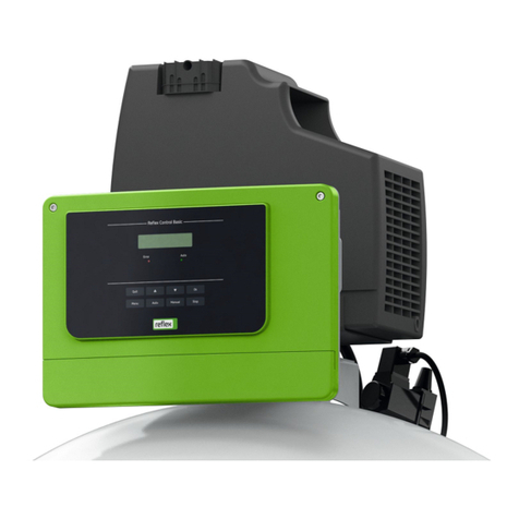
Reflex Fillset Installation instructions

Reflex Fillset
EN
Original operating manual


Contents
Fillset —05-2021
English —3
Contents
1Information concerning the operating manual......................................4
2Safety ........................................................................................................4
3Overview...................................................................................................4
4Technical data..........................................................................................5
5Installation................................................................................................5
6Commissioning and maintenance..........................................................7
7Appendix ..................................................................................................7
7.1 Reflex Customer Service........................................................................ 7
7.2 Warranty................................................................................................. 7
English
05-2021
Contents

Information concerning the operating manual
4 —English
Fillset —05-2021
1Information concerning the operating manual
This operating manual is an important aid for ensuring the safe and reliable functioning of the Fillset. Reflex
Winkelmann GmbH accepts no liability for any damage resulting from failure to observe the information in this
operating manual. In addition national statutory regulations and provisions in the country of installation must also
be complied with (concerning accident prevention, environment protection, safe and professional work practices,
etc.).
2Safety
Reflex Fillset is a prefabricated valve set for direct connection of drinking water systems with heating or cooling
circuits for make-up purposes. System separation in accordance with DIN 1988 T 4 or DIN EN 1717 is
implemented using a DVGW (German Technical and Scientific Association for Gas and Water) approved system
isolator (type BA). This can be used up to hazard class 4.
Control of the make-up volume according to VDI 2035, is implemented using a water meter. Testing and repair
work may only be carried out by authorised persons.
CAUTION
Risk of burns on hot surfaces
Be careful when working on a hot system. Especially with compression couplings, there is a risk of scalding in
the event of water leaks, or injury due to high temperatures in the event of accidental contact.
•Wear protective gloves.
•Please place appropriate warning signs in the vicinity of the device.
•Only use the manufacturer's original parts when replacing parts.
•Suitable measures for temperature and pressure protection in the supply system must be implemented so
that the specified permissible max. and min. operating parameters are not over or undershot.
•Ignoring this manual and the safety information in particular, may cause destruction and defects, endanger
persons and adversely affect the functioning.
•In case of infringement, any claims for warranty and liability are excluded.
3Overview
1
Shut-off
2
Inlet
3
Dirt trap
4
System isolator
5
Water meter
6
Outlet
7
Wall bracket
8
Drain funnel
–Site-provided collecting
funnel or HAT-40-pipe with
drainage options

Technical data
Fillset —05-2021
English —5
4Technical data
Reflex Fillset as an accessory for the direct connection of the make-up to a potable water supply system (mains)
with DVGW-tested system isolator, type BA. Fillset versions are available with a standard water meter or contact
water meter.
Permissible operating pressure
10 bar
Permissible operating
temperature
0 - 60 °C
Installation position
Horizontal
Length
293 mm
Net weight
1.7 kg
Minimum differential pressure for opening the system isolator
0.8 bar
Flow coefficient K VS
As a single module
0.8 m³/h
In combination with Fillcontrol, Variomat, Reflexomat / Servitec
0.7 m³/h
Connections
Inlet
R ½
Outlet
R ½
Electrical specifications for the contact water meter:
Design
Reed Contact
Max. switching power
4 W DC
Pulse sequence
1 contact/10 l
Connection cable
2 x 0.14 mm²,
1.5 m long
5Installation
ATTENTION
Damage to property!
The Fillset can be damaged by water hammer.
•Ensure that no pressure spikes act on the Fillset (valves, ball valves, solenoid valves) from either the mains
water or system side.
•For example, prevent water hammer by use of a water hammer arrestor or SafeControl.
The Fillset wall bracket of the Fillset must be installed horizontally on the wall.
The make-up line must be integrated into the system in such a way that pressure protection against excessive
mains water pressure is provided by the system-side safety valve. Otherwise, a pressure reducer with a safety
valve must be installed in the make-up line. If sealing water leaks from the discharge funnel as a result of the
operating conditions, it must be drained away below the system isolator by site-provided drainage. After installing
the Fillset, the leak-tightness and function of the system isolator must be checked6 "Commissioning and
maintenance", 7.
Manual make-up
If the Fillset is used for manual make-up or for filling the system, the shut-off must be slowly manually opened or
closed as necessary. The system pressure is to be monitored at the site-provided pressure gauge.

Installation
6 —English
Fillset —05-2021
Automatic make-up
If the Fillset is connected for automatic make-ups such as Reflex Fillcontrol, Servimat, Reflexomat with Fillvalve,
Variomat or Servitec, the shut-off is continuously open during operation.
In the case of a Fillset with a contact water meter, it is cabled with the building control system or Reflex Fillcontrol,
Servitec, Variomat, Reflexomat or Gigamat (see corresponding operating manual). Then the make-up quantity is
evaluated via the corresponding control.
Fillset for manual make-up
1
Filling connection
2
Reflex Fillset
3
Site shut-off valve
4
Pressurisation
Fillset with automatic make-up
1
Filling connection
2
Reflex Fillset
3
Reflex Fillcontrol
4
Incorporation: in the circuit, close
to the diaphragm expansion
vessel
5
Diaphragm expansion vessel
pressurisation

Commissioning and maintenance
Fillset —05-2021
English —7
6Commissioning and maintenance
Commissioning and maintenance work may only be carried out by qualified personnel.
System isolator maintenance
The system isolator is subject to annual maintenance based on DIN EN 1717. The first check is carried out after
the first operating year, then checking is periodic, however, no later than after one year.
Use the connections provided for ball valves and a suitable pressure gauge to perform a function test of the valve.
Cleaning of dirt trap and BA cartridge
•Disconnect the system and mains water lines upstream and downstream of the Reflex Fillset with the aid of
inlet and outlet shut-offs and depressurise the valve.
•Use the maintenance spanner (27 mm AF) to unscrew the BA cartridge closure and remove the cartridge.
•Then undo the two screw connections above the system isolator. Next pull the dirt trap out from the inlet-side
screw connection in an upwards direction.
•Clean the removed components under clear running water.
•After the subsequent assembly, open the two shut-offs.
7Appendix
7.1 Reflex Customer Service
Central customer service
Switchboard: Telephone number: +49 (0)2382 7069 - 0
Customer Service extension: +49 (0)2382 7069 - 9505
Fax: +49 (0)2382 7069 - 9523
Technical hotline
For questions about our products
Telephone number: +49 (0)2382 7069-9546
Monday to Friday, 8:00 a.m. –4:30 p.m.
7.2 Warranty
The respective statutory warranty regulations apply.
Sommaire

SI0643enB / 05-21
Reflex Winkelmann GmbH
Gersteinstraße 19
59227 Ahlen, Germany
Telefon: +49 (0)2382 7069-0
Telefax: +49 (0)2382 7069-9588
www.reflex-winkelmann.com
This manual suits for next models
2
Table of contents
Other Reflex Control Unit manuals

Reflex
Reflex Servitec Mini User manual

Reflex
Reflex Reflexomat Basic RS 90 / 1 User manual

Reflex
Reflex Fillcontrol Plus User manual
Reflex
Reflex Reflexomat Series User manual

Reflex
Reflex Servimat M User manual

Reflex
Reflex Anybus CompactCom Installation instructions

Reflex
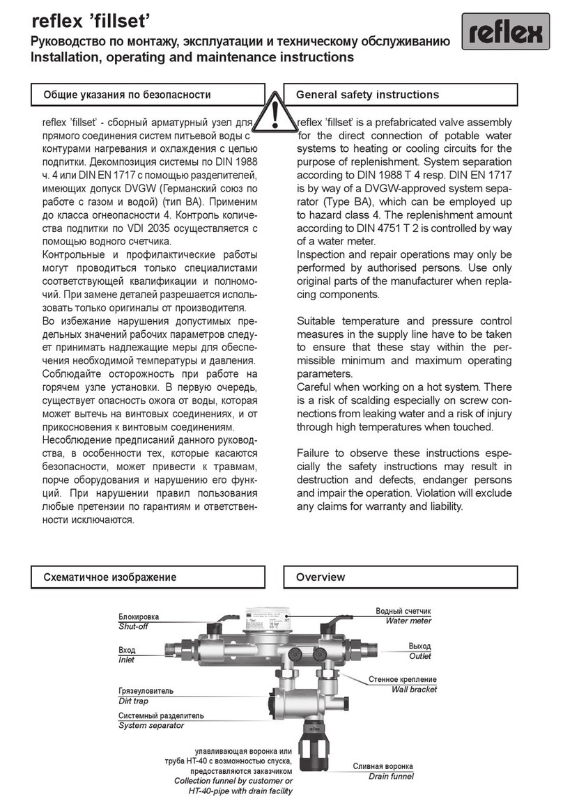
Reflex fillset Assembly instructions
Popular Control Unit manuals by other brands

Giacomini
Giacomini R140D instruction manual

Motorola
Motorola C24 CDMA 1X Hardware Interface Manual

GILBARCO VEEDER-ROOT
GILBARCO VEEDER-ROOT BRCM2.X Installation and Upgrade Instructions

SCT
SCT RC4-E4P Series Application guide

Weidmüller
Weidmüller DPA/RES operating instructions

3monkeez
3monkeez P-3MSS-FVM installation instructions