manuals.online logo
Brands
  1. Home
  2. •
  3. Brands
  4. •
  5. Regal
  6. •
  7. Engine
  8. •
  9. Regal genteq Evergreen OM User manual

Regal genteq Evergreen OM User manual

1
F O R M
Evergreen®OM
Outdoor Fan Motor
Installation Guide
G0038E
Revised
September 2019
Regal Beloit America, Inc.
1325 Heil Quaker Blvd.
LaVergne, TN 37086
Customer Service: 866 503 8566
thedealertoolbox.com
CAUTION indicates a hazardous situation that, if not avoided,
could result in minor or moderate injuries.
• Periodic inspections should be performed. Failure to perform
proper maintenance could result in premature product failure.
• Installation and service of this motor should be performed only
by trained and qualified service technicians familiar with the
Evergreen®OM motor and the HVAC systems into which it will
be installed.
WARNING indicates a hazardous situation that, if not avoided, could
result in death or serious injury.
• Read and follow all instructions carefully.
• Disconnect and lock out the main power from the unit being
serviced before installing the Evergreen®OM motor. It is also a
good practice to confirm that the power is disconnected with a
voltmeter.
• Do not operate equipment without guards in place.
• Improper installation, adjustment, alteration, service,
maintenance, or use could cause explosion, fire, electrical shock,
or other conditions. Consult a qualified installer, service agency,
or your distributor or branch for information or assistance.
The qualified installer or agency must use the supplied or
recommended parts when installing or servicing this product.
• After installing the Evergreen®OM motor, it is the responsibility
of the installing technician to verify the HVAC system matches
the manufacturer’s requirements for proper operation, capacity,
efficiency and safety.
Page 1 6301 & 6303 mechanical installation
Page 1-2 6303R (Remote Mount) mechanical installation
Page 3 6301, 6303 & 6303R (Remote Mount) electrical connections
Page 4 Specifications, diagnostics and warranty information
Evergreen®OM Models 6301 & 6303
Mechanical Installation
Install the motor using the extended clamp-bolts or belly band mount.
Changing Rotation
From the factory, the motor will be set up for CCW rotation, as viewed from
lead end.
The Yellow wire connected thru the 2 pin connector to the Violet wire and the
Orange wire connected thru the 2 pin connector to the Brown wire.
To change the rotation from CCW to CW:
• Disconnect the 2 pin connector and rotate it 180° so the Yellow wire is
connected to the Brown wire thru the 2 pin connector and the Orange
wire is connected to the Violet wire thru the 2 pin connector.
Evergreen®OM Models 6303R (Remote Mount)
Mechanical Installation
The hardware described in the mounting instructions for the motor and the
motor control are located in the parts bag, in the box with the motor, with the
exception of the four (4) mounting screws in the side of the motor.
There are two components to install, the motor and the motor control.
There is a break point in the umbilical cord between the motor control and
the motor comprised of four quick connect terminals. These terminals can be
separated to make it easier to install each component and for routing of the
umbilical cord through the wiring conduit if applicable.
This installation guide covers Evergreen®OM models 6301, 6303 and 6303R (Remote Mount).
Yellow
Orange
CCW (Factory)
Violet
Brown
Yellow
Orange
CW
Brown
Violet
Rotation Connector
CAUTION: Secure all wires, including the Rotation Connector,
out of the path of the fan blade before starting the motor!
Motor
Umbilical Cord
Line Voltage
Harness
Motor Control
2
Evergreen®OM Models 6303R (Remote Mount)
Mechanical Installation (Continued)
This motor is approved for all angle mounting. When the motor is mounted in
the vertical shaft down (VSD) or vertical shaft up (VSU) position, remove the
drain hole plug on the bottom end shield. When the motor is installed in the
horizontal position, rotate the motor so the motor leads exit between the 4
and 8 o’clock position and remove the lead end drain plug.
Mount the motor using one of the following methods that best matches the
installation of the motor being replaced.
• Extended clamp bolts using the four (4) serrated nuts provided if needed.
• Four (4) OEM mounting holes in the end shield with four (4) thread
forming screws provided.
NOTE: IF THESE SCREWS ARE NOT USED FOR MOUNTING, DO
NOT INSTALL THEM.
• Four (4) OEM side mounting holes with screws installed. These screws
are shipped installed in the motor.
NOTE: LEAVE THESE SCREWS INTHE MOTOR IF THEY ARE NOT USED.
• Belly band.
Mount the Motor Control
Two (2) thread forming screws are provided for mounting the motor control.
Drill 1/8” holes if needed to install.
The motor control can be mounted vertically or horizontally. If mounted
vertically (see example installation image to the right), mount with the
harnesses facing down between the 4 and 8 o’clock position.
NOTE: The motor control should not be mounted horizontally in the
bottom of the HVAC unit.
The motor control should be mounted in the airstream of the fan motor. Do
not mount the motor control in a fully enclosed area. Confirm the location is
within the lead length of the umbilical cord.
Route the umbilical cord from the motor to the motor control and secure if
needed to ensure it does not interfere with the path of the fan blade.
Connect the umbilical cord break point for proper rotation (rotation is viewed
from lead end of the motor).
CCW rotation: Red – Red / Blue – Blue / Black – Black (as shipped)
CW rotation: Red – Blue / Blue – Red / Black – Black
NOTE: MAKE SURE THE SILVER GROUND WIRE TERMINALS ARE
CONNECTED TOGETHER.
NOTE: If there is adequate space to route the umbilical cord break point
connection into the electrical panel, the motor can be easily reversed after
the fan shroud and motor are installed. This connection point can be located
outside of the electrical panel.
Route the motor control line voltage connection harness to the electrical
panel.
Secure the harness if needed to ensure the wires do not interfere with the
path of the fan blade.
CCW Rotation
(as shipped)
Red-Red
Blue-Blue
Black-Black
Ground-Ground
CW Rotation
Red-Blue
Blue-Red
Black-Black
Ground-Ground
Motor
Umbilical
Cord
Motor
Control
(example
vertical
installation)
Line
Voltage
Harness
Example Installation
3
High Voltage POWER Connections
Step 1: Connect the Black L1 to Line Voltage L1 on the “LOAD” side of
the contactor.
Step 2: Connect the White L2 to Line Voltage L2 on the “LOAD” side
of the contactor.
Note: Single Pole Contactors, connect the White wire to the unswitched side.
Step 3: Connect the Green/Yellow stripe ground wire to system ground.
High Voltage SIGNAL Connections
Step 1: Connect required speed wire (Orange or Yellow) to the High
Voltage POWER L1 piggy back terminal
A) Orange wire = 8 pole speed (850 RPM)
B) Yellow wire = 6 pole speed (1100 RPM)
Step 2: Cap off unused speed wire with wire nut and/or electrical tape
High Voltage POWER Connections
Step 1: Connect the Black L1 to Line Voltage L1 on the “LOAD” side of
the contactor.
Step 2: Connect the White L2 to Line Voltage L2 on the “LOAD” side
of the contactor.
Note: Single Pole Contactors, connect the White wire to the unswitched side.
Step 3: Connect the Green/Yellow stripe ground wire to system ground.
High Voltage SIGNAL Connections
Step 1: Connect required speed wire (Orange or Yellow) to the Defrost
Control line voltage fan output terminal
A) Orange wire = 8 pole speed (850 RPM)
B) Yellow wire = 6 pole speed (1100 RPM)
Step 2: Cap off unused speed wire with wire nut and/or electrical tape
Green/Yellow Stripe
White
Black
Orange (850 RPM)
Yellow (1100 RPM)
Connect one
Speed Selection
to L1 (Black)
piggy back
System Ground
Load Side
To Compressor and
Fan Motor
Line Side
From Unit
Disconnect
Evergreen
OM
(230V)
Green/Yellow Stripe
White
Black
Orange (850 RPM)
Yellow (1100 RPM)
Connect one
Speed Selection
to Defrost Control
ODF
Defrost
Control
System Ground
Load Side
To Compressor
and
Fan Motor
Line Side
From Unit
Disconnect
Evergreen
OM
A/C Applications Heat Pump Applications
Evergreen®OM Models 6301, 6303 & 6303R (Remote Mount)
Electrical Connections
4
Regal, Evergreen and Genteq are trademarks of Regal Beloit Corporation or one of its affiliated companies.
©2017, 2019 Regal Beloit Corporation, All Rights Reserved. MCIM19028E • Form G0038E • Printed in USA
Specifications:
Voltage: 208-230 (allowable voltage range 196-264) VAC, single-phase
input, 50-60 Hz
Horsepower:
• 1/5 HP (replaces 1/10-1/5)
• 1/3 HP (replaces 1/10-1/3)
Speeds: 2 operating speeds (Constant Speed)
• 1100 RPM (6-pole) replaces motors rated 1000-1100 RPM
• 850 RPM (8-pole) replaces motors rated 800-850 RPM
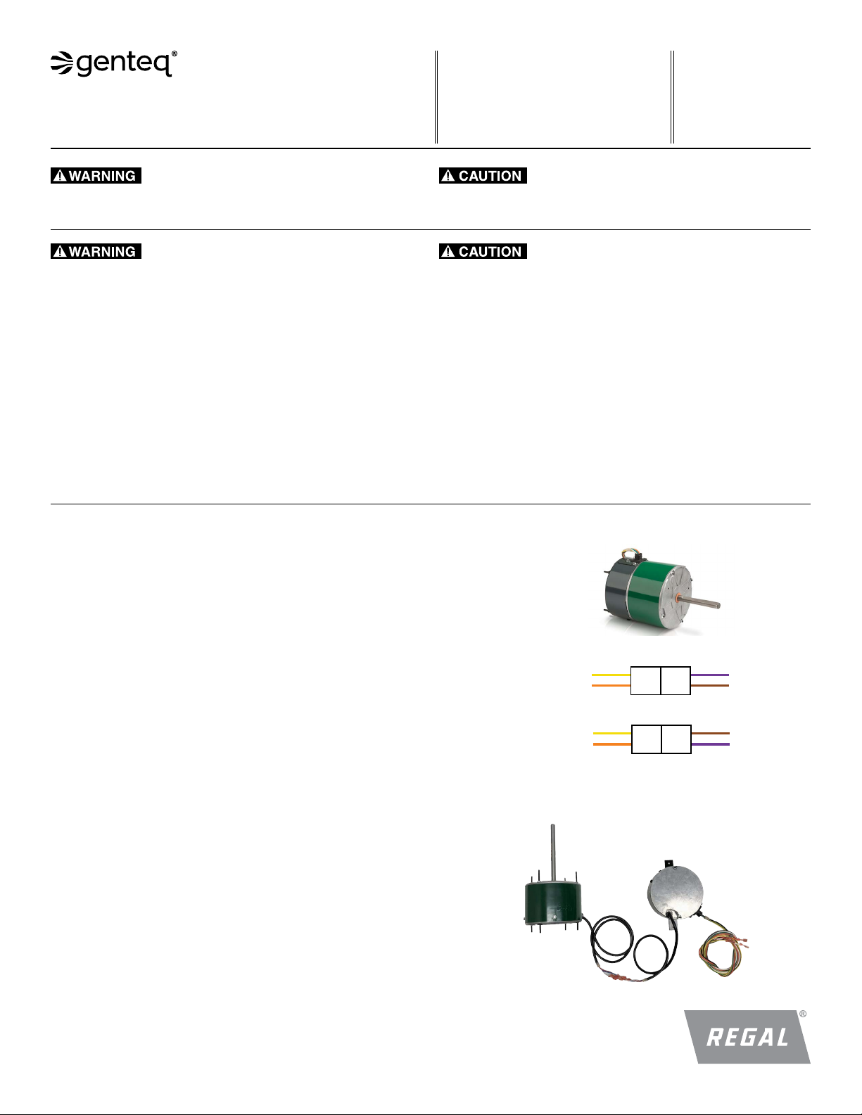
Rotation: CCW or CW by reversing plug or quick connect terminals
(factory set to CCW)
• As viewed from lead end
Bearing: Permanently lubricated ball bearing
Ambient Rating: 60° C
Enclosure: Totally Enclosed Air Over (TEAO), NEMA®48-frame
Shaft:
• 6301 & 6303 - Single, 1/2” diameter, 3” length, 2.5” single flat
• 6303R - Single, 1/2” diameter, 5.5” length, 5” single flat
Mounting:
• 6301 & 6303 - Horizontal or vertical shaft-down (VSD), belly band
or extended clamp bolts.
• 6303R - All angle mount with extended clamp bolts, OEM side or
rear mounting holes or belly band.
Leads: 54” length with ¼” fast on terminals, ground wire #10 eyelet
UL and CSA recognized component
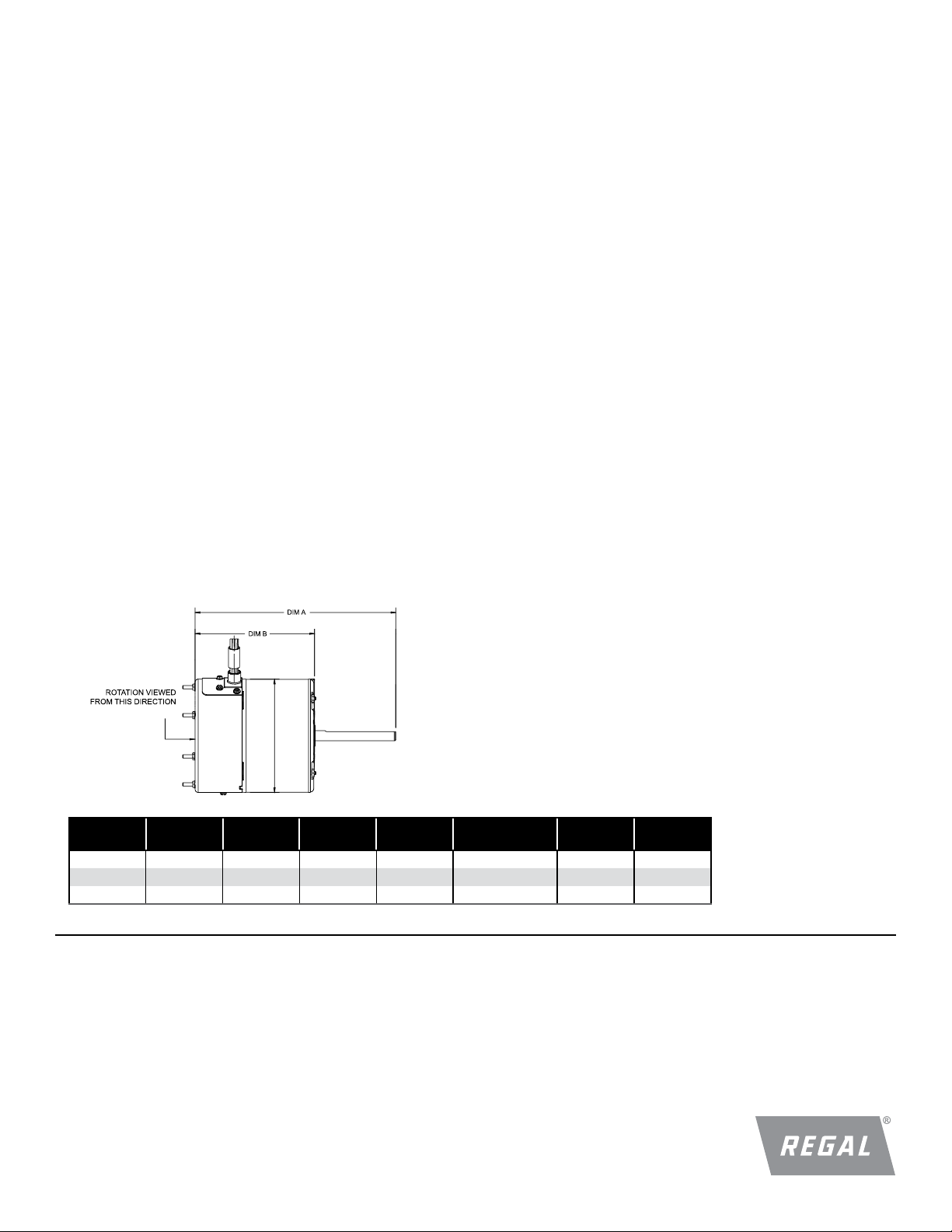
STOCK
NO. HP VOLTS MAX
CURRENT RPM SHAFT DIM A DIM B
6301 1/5 - 1/10 208-230 2.8 850/1100 .5” x 3” (2.5” SF) 8.49” 5.45”
6303 1/3 - 1/10 208-230 3.5 850/1100 .5” x 3” (2.5” SF) 8.99” 5.95”
6303R 1/3 - 1/10 208-230 3.5 850/1100 .5” x 5.5” (5” SF) 9.79” 4.23” *
* This dimension represents the motor length from end shield to end shield excluding control.
Application Note:
This product is designed to replace induction motors (shaded pole
or PSC) in direct-drive fan propeller applications. Do not use this
motor to replace OEM ECM outdoor fan motors or belt drive mo-
tors. OEM ECM outdoor fan motors must be replaced with OEM
equivalent.
The constant speed programming in this motor is what gives it the
ability to replace a range of horsepower ratings with one speed
selection.The speed selection provides the motor with an RPM
operating point.The motor then uses only the torque (amperage)
necessary to achieve this RPM operating point based on the size of
the fan blade (load). To accomplish this the motor constantly moni-
tors its operating speed RPM in real time.
Operation Note:
The Evergreen OM motor will delay turning on approximately 5 seconds
after L1 or L2 voltage is applied to one of the speed wires, then ramp
up to speed. The Orange and Yellow speed wires dictate the on/off
command to the motor control.
Technical Support:
If the motor does not operate with proper Line Voltage measured
between the White wire and the Black wire, AND between the White
wire and the Speed Selection, it has failed and will require replacement.
Before replacing the motor, please call the Contractor Hotline (1-866-
503-8566) to confirm your diagnostics if possible.
We will only provide support for Evergreen products to trained and
qualified service technicians familiar with the Evergreen OM motor and
the HVAC systems into which it will be installed. Technical support will
only be provided related to the proper operation of the Evergreen OM
motor.
The Evergreen OM motor is a single component replacement.The
control cannot be replaced separately from the motor. Contact the
distributor where the motor was purchased or any authorized Evergreen
motor distributor for replacement.
Evergreen®OM Models 6301, 6303 & 6303R (Remote Mount)
NEMA is believed to be the trademark and/or trade name of National Electrical Manufacturers Association
and is not owned or controlled by Regal Beloit Corporation.
Terms & Conditions of Sale & Limited Warranty
Sales of the products described in this Installation Manual are subject to the “Regal Beloit Terms and Conditions of Sale” current at the time of sale. They are accessible on
RegalBeloit.com – https://www.regalbeloit.com (click “Regal Terms and Conditions of Sale”).
The full Limited Warranty, including the scope and period, remedies, exclusions and disclaimers, is described in Section 10 “Limited Warranty” of the Regal Terms and
Conditions of Sale and applies except as described below:
Section 10(a)(1) is replaced with the following: Seller warrants that the Products shall be delivered free from defects in material, workmanship and title. This warranty
shall expire twenty-four (24) months from first use of the Product or thirty (30) months from date of manufacture of the Product, whichever occurs first.

Other Regal Engine manuals

Regal Genteq KRYO FORTRESS User manual

Regal

Regal Genteq KRYO FORTRESS User manual

Regal Century VGreen 085 User manual

Regal

Regal Century VGreen 085 User manual

Regal Genteq Evergreen EM User manual

Regal

Regal Genteq Evergreen EM User manual

Regal genteq ECM User manual

Regal

Regal genteq ECM User manual

Regal genteq Evergreen CM User manual

Regal

Regal genteq Evergreen CM User manual

Regal Century V-GREEN 165 User manual

Regal

Regal Century V-GREEN 165 User manual

Regal genteq Evergreen OM User manual

Regal

Regal genteq Evergreen OM User manual

Regal marathon PPA Series Manual

Regal

Regal marathon PPA Series Manual

Regal Genteq Evergreen IM User manual

Regal

Regal Genteq Evergreen IM User manual

Regal Century VGreen 270 User manual

Regal

Regal Century VGreen 270 User manual

Regal Century VGreen Evo Guide

Regal

Regal Century VGreen Evo Guide

Regal Genteq Evergreen OM User manual

Regal

Regal Genteq Evergreen OM User manual

Regal Century Manual

Regal

Regal Century Manual

Popular Engine manuals by other brands

Kohler K482 Service manual

Kohler

Kohler K482 Service manual

Fuji Imvac BT-24M Operator's manual

Fuji Imvac

Fuji Imvac BT-24M Operator's manual

Emerson Leroy-Somer FFB installation guide

Emerson

Emerson Leroy-Somer FFB installation guide

HE PARAMOTORES MVL 125 user manual

HE PARAMOTORES

HE PARAMOTORES MVL 125 user manual

Portos A-OK user manual

Portos

Portos A-OK user manual

Ruggerini RM 80 Maintenance information

Ruggerini

Ruggerini RM 80 Maintenance information

Barrus Shire 15 Work Boat YM Original instruction

Barrus

Barrus Shire 15 Work Boat YM Original instruction

Vex Robotics Falcon 500 user guide

Vex Robotics

Vex Robotics Falcon 500 user guide

Stiga TM 60 Operator's manual

Stiga

Stiga TM 60 Operator's manual

Man D2868 LE426 Operating	 instruction

Man

Man D2868 LE426 Operating instruction

Perkins 1204F-E44TA Operation and maintenance manual

Perkins

Perkins 1204F-E44TA Operation and maintenance manual

Audi 4.2-litre V8 FSI Service training

Audi

Audi 4.2-litre V8 FSI Service training

M-Elec 5411a user manual

M-Elec

M-Elec 5411a user manual

PrimaLuceLab SESTO SENSO 2 user manual

PrimaLuceLab

PrimaLuceLab SESTO SENSO 2 user manual

Desert Aircraft DA100 owner's manual

Desert Aircraft

Desert Aircraft DA100 owner's manual

Kohler Courage XT-6 Service manual

Kohler

Kohler Courage XT-6 Service manual

Fiamma Polar White 08318-01P Installation and usage instructions

Fiamma

Fiamma Polar White 08318-01P Installation and usage instructions

DANA 4360-52 parts list

DANA

DANA 4360-52 parts list

manuals.online logo
manuals.online logoBrands
  • About & Mission
  • Contact us
  • Privacy Policy
  • Terms and Conditions

Copyright 2025 Manuals.Online. All Rights Reserved.