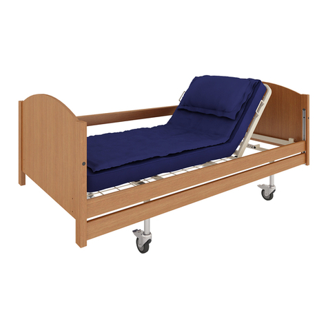
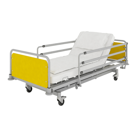
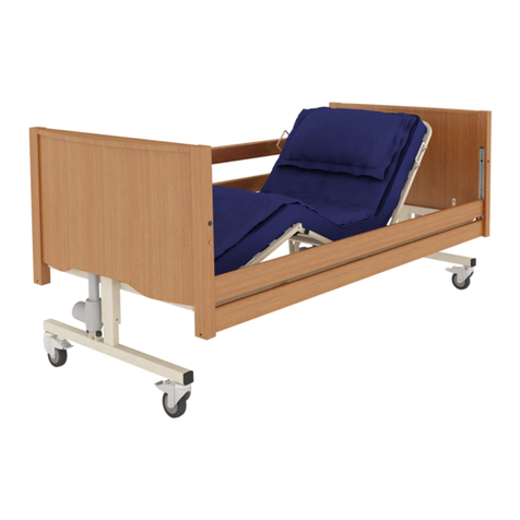
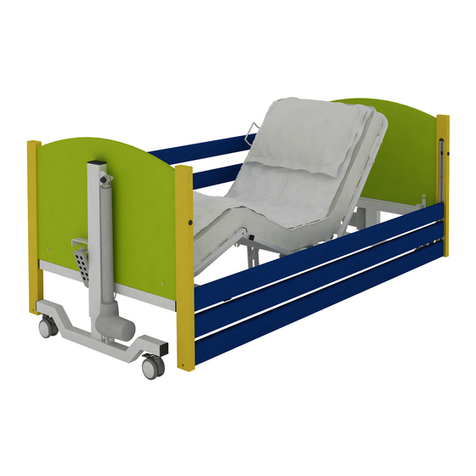
Rehabed LEO User manual


2

3
CONTENTS
1. INTRODUCTION ....................................... 4
1.1. CONTACT........................................... 4
1.2. TO WHAT IT CONCERNS? ...................... 4
1.3. FEATURES.......................................... 4
1.4. USE .................................................. 5
1.5. CONTRAINDICATIONS........................... 6
2. WARNINGS AND CAUTIONS.................... 7
2.1. GENERAL WARNINGS ........................... 7
3. TRANSPORT AND STORAGE .................. 11
4. SYMBOL DEFINITIONS ........................... 13
5. PARTS .................................................... 15
5.1. PARTS SPECIFICATION ........................ 15
6. BED ASSEMBLY AND PREPARING FOR USE
................................................................... 16
6.1. FITTING ELECTRICAL SYSTEM................ 16
6.1.1. HOLDER ARRANGEMENTS ON
POWER CABLE................................................ 18
6.2. ASSEMBLING THE WOODEN BED ENDS .. 18
6.3. FITTING THE WOODEN,FULL-LENGTH SIDE
RAILS............................................................ 19
6.4. FITTING THE LIGHT SIDE RAILS ............. 20
6.5. FITTING THE SPLIT SIDE RAILS............... 20
6.6. CHECKING THE BED............................ 22
7. TRAINING............................................... 23
8. FIRST USE............................................... 24
8.1. OPERATIONAL LIMITS......................... 24
8.2. GENERAL SAFETY............................... 25
8.3. PREPARING FOR START....................... 25
8.4. BRAKE SYSTEM ................................. 26
8.4.1. CASTORS WITH INDIVIDUAL LOCK 27
8.4.2. AXEL LOCK OF THE CASTORS ...... 27
8.4.3. CENTRAL LOCK OF THE CASTORS . 27
8.5. SIDE RAILS AND MATTRESSES............... 27
8.5.1. SIDE RAIL SAFETY .....................28
8.5.2. MATTRESS THICKNESS ..............28
8.5.3. OPERATING THE WOODEN,FULL-
LENGTH SIDE RAILS..........................................29
8.5.4. OPERATING THE LIGHT SIDE RAILS
...................................................................29
8.5.5. OPERATING THE SPLIT SIDE RAILS 29
8.6. ELECTRICAL OPERATION......................30
8.6.1. HANDSET LOCATION.................31
8.6.2. 10 AND 9-BUTTON HANDSET
OPERATION....................................................32
8.6.3. HANDSET LOCKOUT..................33
8.7. LEG SECTION.....................................33
9. DISASSEMBLING THE BED FOR
TRANSPORT ...............................................35
10. POWER FAILURES ................................ 37
10.1. EMERGENCY LOWERING BACKREST AND
LEG SECTIONS.................................................37
11. DECONTAMINATION............................ 39
12. MAINTENANCE .................................... 41
12.1. GENERAL MAINTENANCE..................41
12.2. SERVICE LIFE...................................43
12.3. FAULTY FINDING..............................44
13. DISPOSAL OF PARTS ............................45
14. ELECTROMAGNETIC COMPATIBILITY
(EMC) .........................................................46
15. SPECIFICATION.....................................47
15.1. BED DATA ......................................47
15.2. MAXIMUM LOAD ............................47
15.3. TECHNICAL DATA OF SIDE RAILS..........48
15.4. ELECTRICAL DATA ............................49
16. ACCESSORIES ....................................... 50
16.1. MATTRESS AND SIDE RAILS ................51
17. LIFTING POLE .......................................53
18. WARRANTY ..........................................54
18.1. WARRANTY CONDITIONS ..................54

4
1. INTRODUCTION
Thank you for your trust and purchase of our product. Before using the bed, please
read this instruction manual carefully and make sure it is fully understood. In the case
of any doubts concerning the installation, use or maintenance of the bed, please
contact the seller or the manufacturer.
1.1. CONTACT
In order to get help with the installation, use or service of the product, as well as to
report an unexpected operation or to obtain any information regarding service,
warranty, sales or customer service concerning this product, please contact your seller,
distributor or (in case of doubt) with Reha-Bed Sp. z o.o. at the following address:
Reha-Bed Sp. z o.o.
Spacerowa 1 Street
41-253 Czeladź
Poland
In service matters (including spare parts):
e-mail address: serwis@rehabed.com.pl
phone: +48 519 842 766
phone: +48 608 727 090
Other issues:
e-mail address: biuro@rehabed.com.pl
phone: +48 608 727 090
Each serious incident connected with the device should be reported to
Reha-Bed Sp. z o.o. and the competent authority of the Member State, where the
device is used. Please provide the product serial number (LOT) in all correspondence.
You can find it on the identification labels, which are located on the inside of the
backrest section frame and the leg section frame, as well as on the bottom of each bed
ends.
In order to receive support outside of Poland, please contact the local distribution
company, which sold you the device.
1.2. TO WHAT IT CONCERNS?
This instruction manual applies to Leo beds consisting of 4-section mattress platform
with metal slats and electrically operated backrest and knee break.
All products are CE marked –in accordance with the EC Directive on med
ical devices (2017/745 (MDR)).
1.3. FEATURES
▪4 separate sections (movable back and leg section)
▪Electrically controlled back and leg section position
▪Mechanical adjustment of the foot section
▪Auto contour – simultaneous adjustment of back and leg sections

5
▪Stepless electric adjustment of bed’s height and tilt: reverse-Trendelenburg
and Trendelenburg* (available for hospital environment and nursing homes)
▪Lockable handset (remote control)
▪Wooden side rails or split side rails along the entire length of the mattress
platform or steel Light side rails
▪Emergency power system (optional)
▪Electrical system IPX4 rated – Splash resistant
▪Axel or central brake system (optional)
*If patient requirements are such that Trendelenburg functionality
is deemed to pose a potential risk a replacement handset can be
purchased with the Trendelenburg function removed. Contact you
seller or the manufacturer.
1.4. USE
The Leo bed with scissor-pantograph mechanism has been designed to provide the
user with optimal independence and freedom whilst aiding the manual handling
requirements of the carer. The Leo bed with a 9-button handset (Trendelenburg
position locked-off) is intended for use within domestic environment. A 10-button
handset is intended for use in the following environments in long-term care facilities,
where medical care and health monitoring are required (e. g. nursing homes,
rehabilitations centres, geriatric wards).
The bed significantly relieves a caregiver thanks to a fully electrically profiled platform
that enables to adjust the position to the user’s needs.
The bed is designed for users with a minimum height from 146 to 185 cm (when the
bed length extension is not fitted), BMI greater than 17 and a maximum weight up to
178 kg. The lower (or upper) age limit is not defined. The usability of the bed depends
on the physical size of the patient in relation to the various proportions and spaces
around the bed’s frame. It is not intended for patients weighting less than 40 kg.
The bed is intended for one person only!
The bed is designed to support the patient’s weight (as described above) while
sleeping or resting. It assists in the care and/or ensures comfort for the patient or
caregiver –when the bed is used in long-term care facilities.
It is the carer’s responsibility to determine that the patient is both mentally and
physically capable of occupying the bed with minimal risk of personal injury.
▪A risk assessment must always be performed on the suitability
of the patient to the bed frame and any ancillary accessories.

6
▪If there are any doubts to use the product should be consulted
with a health care professional (e.g. physiotherapist, doctor).
Make sure the product is suitable for your condition or
dysfunction.
1.5. CONTRAINDICATIONS
The contraindications for using the Leo bed include:
▪Cervical or skeletal traction,
▪Unstable fractures of the spine –if the bed’s functions remain unlocked,
▪General fractures of the skeleton –if the bed’s selected functions remain
unlocked,
▪Level of mental development that makes it impossible to safely operate the
bed’s functions – if the bed functions remain unlocked,
▪Confusion, agitation or unstable emotional state of the patient –if side rails
are installed and/or they are in the highest position,
▪Exceeding the maximum patient’s weight,
▪Inadequate height of the patient (below 146 cm or above 185 cm),
▪Inappropriate BMI of the patient (below 17),
▪Inadequate weight of the patient (less than 40 kg).
Consider the presence of other contraindications that are specific for the patient of
the care environment.

7
2. WARNINGS AND CAUTIONS
Warnings in this instruction manual indicate potential hazards,
disregard of which could lead to injury or death.
Cautions in this instruction manual identify potential hazards,
disregard of which could result in damage to the equipment.
2.1. GENERAL WARNINGS
▪READ THE INSTRUCTION MANUAL CAREFULLY before use or
installation.
▪The user is obliged to observe this instruction.
▪The bed is to be installed and put into service in accordance
with the information provided in these instructions for use.
▪The bed should be used in acceptance with its intended
purpose.
▪The bed is not suitable for children. If used by a child, ensure
that a risk assessment has been conducted –taking into
account the child’s proportions and the dimensions of the bed’s
frame.
▪The bed is not suitable for users with a height less than 146 cm
–in case of doubt, please contact the local distributor, importer
or manufacturer.
▪The bed is not suitable for users weighting less than 40 kg –in
case of any doubt, please contact the local distributor, importer
or manufacturer.
▪The bed is not suitable for users with a BMI less than 17 - in
case of any doubt, please contact the local distributor, importer
or manufacturer.
▪Misused electrical equipment may be hazardous.
▪Accessories that have not been designed for use with the bed
should not be used.
▪The use of additional mechanical or electrical devices that are
not intended for use with the bed is unacceptable.
▪Only original spare parts supplied by the manufacturer are
allowed.
▪The bed cannot be used if any screws/parts are missing.
▪During transport, hold only the constant, massive parts of the
bed ends!

8
▪During assembly / disassembly and regular operation,
particular attention should be paid to the risk of hand injury.
▪Start and use of the defective device that could pose a risk to
patients or others is forbidden.
▪Actuators should not be used in the presence of flammable
gases.
▪The bed should be used and kept away from heat sources and
open flames (e. g. cigarettes, electric fire, heaters, etc.) –risk
of explosion / fire.
▪It is forbidden to open covers of actuators, control box and
power supply! Disassembly and seal break will void the
warranty and create risk of electric shock!
▪Particular attention should be paid to current wiring not being
among movable parts of backrest / leg section and high / low
system of the bed, which may cause malfunction.
▪All lines must be suspended on dedicated brackets, so they are
not frayed and do not touch the floor.
▪Ensure that mains cable is plugged into an appropriate power
source at all times.
▪The mains plug is the disconnect device for the means of
isolating the bed from the mains supply, the plug must be
accessible at all times.
▪Pulling the plug out of the socket is permissible only for holding
the body of the plug / adapter, not the cord.
▪Inappropriate handling / positioning of the mains cable could
cause kinking or shearing of the cable which may lead to
exposed live wires - risk of electrocution.
▪If you cannot plug the main power cable directly into a wall
socket, only the CE marked extension cables may be used.
▪If the product is connected to the power supply with an
extension cable, never overload the product by connecting
devices that exceed the maximum rating of the extension cable
–risk of fire.
▪Make sure that there are not many sockets under the frame –
liquids that may seep into such a socket during normal use of
the bed may pose electrical/fire hazard.
▪The place of use of the bed there should be no obstacles to the
proper operation or installation.
▪Setting up and using the bed should be on flat, horizontal
surfaces so that all the castors touch the ground.
▪Before each use, check the bed and lock all four wheels.
▪Wheels should be locked/unlocked by foot, not by hand.

9
▪The bed should be in the lowest position if the patient is left
unattended, in order to minimize the risk of injury caused by a
fall.
▪A handset must be locked if the patient should not change the
height and/or tilt of the back and/or leg sections, or when there
are doubts concerning the patient’s ability to safety control the
functions of the bed.
▪In the absence of supervision of the patient (if such
circumstances occur), the bed should be set to the highest
position of railings on both sides of the bed. Unlocking and
lowering them can be done only by the person responsible
(care person or nurse).
▪The patient should not be left in the Trendelenburg or reverse
Trendelenburg position!
▪The bed is not intended for patient’s transportation. The
manufacturer allows moving the bed with patient within the
room to clean or gain access to the patient. In such a case,
special attention should be paid to disconnect the bed from the
power supply before transporting the bed. The transportation
should take place in the lowest position of the mattress
platform while maintaining the patient in the horizontal lying
position.
▪Side rails must be installed on both sides of thebed (on the side
of the wall as well).
▪Standard height side rails enable to use mattresses with a
maximum height of 150 mm.
▪The height extension of the side rails enables to use mattresses
with a maximum height of 270 mm.
▪Side rails may only be used with proper size mattresses
intended for the bed –otherwise there is a risk of the user
entrapment.
▪Leaning against or resting on rails may cause accidents!
▪Leaning out of the bed is a threat of injury!
▪In case of damage to the rails (bending, breaking, cracking etc.),
they should be immediately replaced with new ones due to the
risk of an accident.
▪Placing limbs between the moving elements of the bed may
cause injury and accidents.
▪Do not exceed the safe working load of the bed!
▪Maximum operating time of actuators is 2 minutes for 18
minutes break. Failure to comply with the afore-mentioned
will result in permanent damage to the actuator.

10
▪During the adjustment and maintenance attention should be
paid to ensure that no part of the body is found in the
potentially hazardous section (movable: backrest section, leg
section, high / low system, side rails) - risk of injury to the limbs!
▪Particular attention should be paid to small children, the
patient's limb or other items around the bed that could entrap
in a space between mattress platform and the chassis and be
damaged or injured.
▪Do not sit on the raised sections of the back, thigh and lower
leg.
▪Bear in mind that self-repair poses a risk of accidents or
damage to the bed!
▪Maintenance, repair and disinfection may be conducted only
by specially trained persons.
▪It is forbidden to modify the bed’s frame without the consent
of the manufacturer –this poses a risk of danger.
▪Precautions are to be taken when routing cables from external
equipment around the bed to ensure that they do not become
squeezed, trapped or damaged - risk of electric shock and/or
fire.
▪All electrical components that are a part of the bed and/or
related accessories, which are damaged, must be immediately
withdrawn from service and replaced –damaged electrical
components may present a risk of electric shock/fire.
▪If the bed will be used with a hoist, make sure that there is
enough space under the bed to lower the bed to the lowest
possible position of the mattress platform –risk of crushing of
the bed’s frame.
▪Due to the small space under the bed, special attention should
be paid to young children, user limbs and other items around
the bed that could be trapped between the bed’s components
and injured or damaged.
▪The RF emissions from the electrical system are very low and
are not likely to cause any interference to nearby electronic
equipment, however interference to sensitive equipment is
possible (see section 14 for further detail).
▪Deformed lifting pole should be promptly replaced.
▪ALL THE ABOVE WARNINGS AND CAUTIONS SHOULD BE STRICTLY ADHERED
TO.

11
3. TRANSPORT AND STORAGE
The following conditions should be followed when transporting and storing the bed:
▪Bed always to be stored on a flat and level floor.
▪Bed ends set to minimum height.
▪Side rail components (not including wooden side rails) to be kept in the aluminum
channels on the bed ends (or stored safely together).
▪Wheel brakes should be applied.
▪All profiling sections secured with hook and loop tape (or similar).
▪All electrical functions of the bed locked out.
▪Make sure that all fasteners (such as screws, washers, plugs, etc.) are carefully
tightened and secured for transport.
▪Covered to protect from fluid ingress, dirt, dust etc.
▪Beds must not be stored one on top of another.
▪Beds not to be stored on their side.
Environmental conditions:
Operational Limits
Transportation/storage limits
Ambient temperature:
from +10ºC to +40°C
from -20°C to +50ºC
Humidity:
30% - 75%
30% - 75%
Atmospheric pressure:
from 800 to 1060 hPa
Altitude:
≤ 2000 m
≤ 2000 m
▪The bed is not intended for patient transport, it is not to be
moved out of the room it is located in with a patient occupying
the bed - Risk of patient / carer injury. If the bed is to be moved
within the room with an occupant in the bed a risk assessment
in line with local health and safety policy is to be undertaken in
order to ensure that neither staff or patients are put at risk
when moving the bed; this is dependent on the situation and
load on the bed.
▪If transporting the bed ensure a risk assessment in line with
local health and safety policy is undertaken to ensure that staff
are not put at risk when moving the bed, especially in regards
to moving up / down inclines and uneven surfaces.
▪The bed should not be transported if any screws are missing or
sections are not secured - risk of the bed collapsing.
▪In order to prevent the risk of cross contamination, when
removing the bed from its place of use by the end user, make
sure that all actions (connected with the bed) are carried out
with the use of disposable gloves. Next to, properly dispose the
glove, unless it can be verified that the bed and all accessories
have been properly disinfected and cleaned.

12
▪If the bed is removed from its place of use by the end user,
before handing the bed over for storage, make sure that the
bed has been cleaned and disinfected –in acceptance with your
local infection control rules and/or rules that are specified in
this instruction manual (see section 11).
▪If the bed has been transported/stored at a temperature close
to the minimum/maximum values determined above, it should
be left for a minimum of 2 hours in order to reach room
temperature before its connection to the power supply –
operation outside the recommended temperaturesposes a risk
of damage to the electrical system.
▪Avoid exposing the bed to direct sunlight –direct sunlight may
damage the electrical system and/or cause bed’s colour fading
over time (including the fading of the bed’s labels).
▪Avoid placing the bed in a humid environment –a long-term
exposure tomoisture may damage the electrical system and/or
have a detrimental effect on parts of the bed’s frame.
▪Do not use side rails to transport the bed –risk of damage.
▪Do not transport the bed over threshold –risk of damage.
▪When using the bed’s functions, make sure that no furniture or
other things (such as a bedside table) are not an obstacle.
▪Make sure that the bed is positioned in an appropriate distance
from walls/other furniture in order to prevent the damage to
the equipment when operating the bed (especially when
working with a tilted mattress platform).
▪Cable tiles, etc. used for storage should be removed after
assembling the bed, before use –the frame may be damaged
in the event of their leaving.
▪Take special precautions concerning EMC. The bed should be
installed and put into operation in a manner described in
section 14.
▪The bed with an additional source of emergency power supply
is not intended to discharge batteries for a long time and it
should always be connected to the power supply during normal
use –complete discharge may reduce their performance.

13
4. SYMBOL DEFINITIONS
The following symbols are observed on the beds:
Warning
Beware of potential hazard
Cautions
Beware of potential hazard
Refer to instructions for use –recommended
Failure to read the instructions for use could introduce a hazard
Refer to instructions for use –mandatory
Failure to read the instructions for use could introduce a risk
Maximum patient weight
Refer to section 15.2
Safe working load
Refer to section 15.2
WEEE marking - placed on individual parts of electrical system
(Waste electrical and electronic equipment) –see section 13
Application part (type BF)
Application part: a part of the device that comes into physical contact with the patient
and/or user –in order to use it to perform its assigned functions (see section 15.4)
Type BF: application parts that are electrically isolated from earth and other parts of medical
equipment –they comply with the specific requirements for protection against electric
shock in acceptance with IEC 60601-1.
Class II electrical appliance
The user is protected by at least two insulation layers against conductive elements (e. g.
power cable) –in case of noticing damage to the control unit or the power cables,
immediately disconnect the device from the power supply and immediately contact the
supplier or Reha-Bed Sp. z o.o.
Marking of the medical device
Determination of minimum physical requirements for adults
From the left: minimum patient weight, minimum patient height, minimum BMI value of the
patient
Mattress suitability
Refer to section 16.1
Warning –knee break intended purpose
Knee break to be used for lifting patient legs only

14
Warning –dynamic mattress
Dynamic mattresses must only be strapped to moving parts of bed frame
Electrical specification
Including storage and use conditions
Warning –removable side rail
Incompatible and improperly installed side rails may pose a risk of injury or death - see the
instruction manual
Total product weight in transport mode
Heavy weight of the product - be careful when transporting on the transport stand and
assembly
Certification mark
Product meets the requirements of the EC Directive on medical devices (2017/745 (MDR))
Manufacturer data
DOM
Date of manufacturing
LOT
Serial number
Reference number
Product code

15
5. PARTS
5.1. PARTS SPECIFICATION
(The figure shows the Leo bed with wooden side rails)
1. Head end
2. Side rail
3. Side rail channel (aluminum channel)
4. High / Low actuator
5. Backrest mattress platform
6. Backrest section actuator and control box
7. Leg section frame
8. Leg section actuator
9. Castor
10. Side rail release button
11. Foot end
12. Handset (not visible)
13. Lifting pole (optional, not visible)
▪During assembly / disassembly and regular operation,
particular attention should be paid to the risk of hand injury.
▪The bed cannot be used in case a screw is missing.

16
6. BED ASSEMBLY AND PREPARING FOR USE
▪Before attempting to assemble the bed, ensure these
instruction manual has been read and fully understood.
▪Ensure a risk assessment in line with local health and safety
policy is undertaken to ensure that staff are not put at risk
when performing assembly activities.
▪Pay special attention during assembly activities due to the
heavy weight of individual elements.
▪The manufacturer recommends that the bed should be
assembled by two persons.
For assembly, clear the intended area, playing particular attention to the fact that any
movement of the bed will not be obstructed.
Apply the brakes to the castors.
6.1. FITTING ELECTRICAL SYSTEM
The bed is designed to be connected to a constant power supply at all times during
use. An auxiliary emergency power supply is available as an accessory to maintain
the bed's basic functions for a specified period of time if mains power is not
available (see section 10).
▪The bed is delivered with fitted electrical system - the cables are matched to
the graphic on the control box with coloured tags. Ensure the cables are
connected correctly into the corresponding ports.
Without tag
=
Foot end
Without tag
=
Head end
Yellow tag
=
Leg rest
Black tag
=
Backrest
Handset
Note: The two bed ends are identical but plugging them into the correct port is
important for the tilt function to work as intended.

17
▪Check condition of power cable, handset cable and actuators' cables and make
sure they are not damaged.
▪Once all the cables are connected they are to
be secured in place by attaching the retaining
clip.
Note: Actuator and handset cables are not shown
(Image courtesy of DewertOkin GmbH)
▪Connect the mains cable into the socket on
the bottom of the control box, and then plug
the power adapter to the mains system.
Actuator is not shown
(Image courtesy of DewertOkin GmbH)
▪Clip the mains cable into the additional cable holders (see section 6.1.1).
▪Make sure that actuator cables have sufficient length and they are not over-
tightened –the full range of movement for actuators should be possible.
▪Make sure that none of the actuator and/or handset cables are
placed between moving parts of the bed and are not under
excessive tension, and check that cables are not tight
(especially the main power cable when lifting the bed up and
down and/or backrest section control cable) to avoid possible
damages. Damaged cables pose a risk of electric shock and/or
fire.
▪Make sure that both actuators (high/low) are plugged into the
correct ports. If the Trendelenburg or reverse-Trendelenburg
function does not work as expected, the high/low actuators can
be connected in a wrong way.
▪Untightening and break the seals or lid of the actuators, the
control box or the power supply will create risk of electrocution
and void the warranty.
▪Ensure all cables, in particular the mains cable, are free from
moving parts and are not under excessive tension.
▪Pulling the plug out of the socketis permissible only for holding
the body of the plug / adapter, not the cord.
▪Damage to actuators or the control box will void the warranty.
▪Breaking or damaging seals of actuators or the control box will
void the warranty.

18
6.1.1. HOLDER ARRANGEMENTS ON POWER CABLE
Leo bed is equipped with 7 additional cable holders that allow the power cable
suspension under the mattress platform.
The figure below presents the arrangement.
▪All cables must be suspended from the platform frame on
dedicated brackets, to avoid rubbing and cannot touch the
floor.
▪Incorrect placement/deployment of the power cable may
cause the damage or cut of the cable –this situation may
expose live conductors (risk of electric shock).
▪Consider the adequate placement of actuator and/or handset
cables in order to minimize the risk of accidental suffocation as
a result of the entanglement of the user and/or other people.
6.2. ASSEMBLING THE WOODEN BED ENDS
▪Note: If this action is being undertaken the manufacturer recommend that
the castors are braked before assembly commences.
▪Fit bed end sliding the spigot into the platform end and determine the position
of the set screws.
▪Tighten all set and dome head screws, making sure the set screws are tightened
before tightening the dome head screws.
▪Repeat for the other bed end.
▪Cut off/remove the plastic retaining ties/Velcro straps from the head and foot
mattress platforms.

19
6.3. FITTING THE WOODEN,FULL-LENGTH SIDE RAILS
Before installation, make sure that the length of side rails is suitable for the length of
the mattress’s platform (see section 15.3).
▪Lower/raise the bed to its medium height
(see section 8.6.2 regarding the operation
of the bed’s electrical functions).
▪Depress each end’s side rail release button
(see section 8.5.3) and lower the finger
assemblies to the bottom of the channel.
▪On the foot end, remove the retaining
screw at the bottom of the side rail
channel on one side. Do not remove head
end retaining screws.
▪Remove the finger assembly from the channel.
▪Take two side rails (rounded face pointing upward) and slide the end of them into
set of fingers that is still located in the channels at the head end of the bed.
Carefully rest the unattached ends on the floor taking care toensure that the other
ends are sufficiently far into the fingers so that they will not fall out.
▪Take the previously removed finger assembly, place the lift wire over the top finger
set (as shown in the picture below) and insert into the other end of the top side
rail. Slide the finger assembly inside the channel. It is recommended that a second
person holds the rail at this point.
▪Whilst holding the top side rail, slide the plastic spacer
block into the channel and place the upper finger of the
bottom finger set through the hole in the lift wire (as
shown in illustration to the right) and into the other end
of the lower side rail and lift the assembly until a click is
heard.
▪Re-fit the previously removed retaining screw. This
ensures that the side rail finger assembly cannot fall out
of the channel when in the lowered position.

20
▪Repeat the assembly process for the side rails on the
other side of the bed.
▪Check that the side rails function properly and
smoothly. Check that the side rails easily lock into the
highest position to make sure that they are mounted in
a right way.
6.4. FITTING THE LIGHT SIDE RAILS
The Leo bed is delivered with fitted steel Light side rails. The following instructions
may be helpful when you need to replace the side rails or their components.
▪To fit the Light side rails, fix it to the bed according to the below picture, setting
it evenly on both mounting sleeves.
▪Pay attention that the side rails release button is closer to the foot bed end.
Note: the side rails are the same for the right and left sides of the mattress
platform and they may be installed interchangeably.
6.5. FITTING THE SPLIT SIDE RAILS
The Leo bed is delivered with fitted split side rails. The following instructions may be
helpful when you need to replace the side rails or their components.
Table of contents
Other Rehabed Medical Equipment manuals