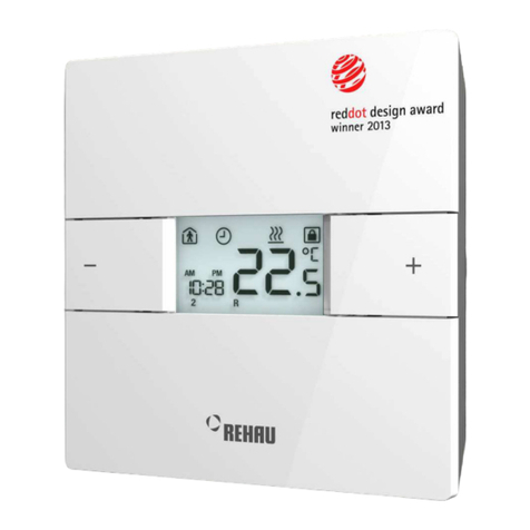
Rehau NEA User manual

SERVICE-MANUAL
NEA ROOM CONTROLLER 230V / 24V
© REHAU
2
SERVICE-MANUAL
ROOM TEMPERATURE CONTROLLER NEA 230V / 24V

SERVICE-MANUAL
ROOM TEMPERATURE CONTROLLER NEA 230V / 24V
3
TABLE OF CONTENTS
1 . . . . . . .
Information and safety guidelines . . . . . . . . . . . . . . . . . . . . . . . . . . . . . . . . . . . . . . . . . . . . . . . . . . . . ..
3
2 . . . . . . .
System description .. . . . . . . . . . . . . . . . . . . . . . . . . . . . . . . . . . . . . . . . . . . . . . . . . . . . . . . . . . . . . . . . .
5
2.1. . . . . .
System components NEA. . . . . . . . . . . . . . . . . . . . . . . . . . . . . . . . . . . . . . . . . . . . . . . . . . . . . . . . . . . . . . .
5
2.2. . . . . .
Functional overview . . . . . . . . . . . . . . . . . . . . . . . . . . . . . . . . . . . . . . . . . . . . . . . . . . . . . . . . . . . . . . . . . . .
6
2.3. . . . . .
Technical data . . . . . . . . . . . . . . . . . . . . . . . . . . . . . . . . . . . . . . . . . . . . . . . . . . . . . . . . . . . . . . . . . . . . . . .
7
3 . . . . . . .
Installation . . . . . . . . . . . . . . . . . . . . . . . . . . . . . . . . . . . . . . . . . . . . . . . . . . . . . . . . . . . . . . . . . . . . . . . . .
10
3.1. . . . . .
System structure . . . . . . . . . . . . . . . . . . . . . . . . . . . . . . . . . . . . . . . . . . . . . . . . . . . . . . . . . . . . . . . . . . . . .
10
3.2. . . . . .
Wiring of NEA H and NEA HT room controllers to NEA H 230V / 24V wiring centre . . . . . . . . . . . . . . . . .
11
3.3. . . . . .
Wiring of NEA H and NEA HT room controller without use of wiring centre . . . . . .. . . . . . . .. . . . . . . . . . .
12
3.4. . . . . .
Wiring of NEA HCT room controllers to NEA HC 24V wiring centre . . . . . . . . . . .. . . . . . . . . . . . . . . . . . .
13
3.5. . . . . .
Wiring of NEA HCT room controllers without use of NEA HC 24 V wiring centre.. . . . . . . . . . . . . . . . . . .
14
3.6. . . . . .
Use of dew point monitors . . . . . . . . . . . . . . . . . . . . . . . . . . . . . . . . . . . . . . . . . . . . . . . . . . . . . . . . . . . . . .
15
3.7. . . . . .
Wiring of NEA timer to NEA wiring centre . . . . . . . . . . . . . . . . . . . . . . . . . . . . . . . . . . . . . . . . . . . . . . . . . .
16
3.8. . . . . .
Wiring of a pump to NEA wiring centres with pump module . . . . . . . . . . . . . . . . . . . . . . . . . . . . . . . . . . . .
17
4 . . . . . . .
Parameterisation and special functions . . . . . . .. . . . . . . . . . . . . . . . . . . . . . . . . . . . . . . . . . . . . . . . . . .
18
4.1. . . . . .
Introduction . . . . . . . . . . . . . . . . . . . . . . . . . . . . . . . . . . . . . . . . . . . . . . . . . . . . . . . . . . . . . . . . . . . . . . . . .
18
4.2. . . . . .
Operating in service and expert level . . . . . . . . . . . . . . . . . . . . . . . . . . . . . . . . . . . . . . . . . . . . . . . . . . . . .
18
4.3. . . . . .
Service level . . . . . . . . . . . . . . . . . . . . . . . . . . . . . . . . . . . . . . . . . . . . . . . . . . . . . . . . . . . . . . . . . . . . . . . .
19
4.4. . . . . .
Expert level . . . . . . . . . . . . . . . . . . . . . . . . . . . . . . . . . . . . . . . . . . . . . . . . . . . . . . . . . . . . . . . . . . . . . . . . .
21
4.5. . . . . .
Special functions . . . . . . . . . . . . . . . . . . . . . . . . . . . . . . . . . . . . . . . . . . . . . . . . . . . . . . . . . . . . . . . . . . . . .
24
5 . . . . . . .
Error messages . . . . . . . . . . . . . . . . . . . . . . . . . . . . . . . . . . . . . . . . . . . . . . . . . . . . . . . . . . . . . . . . . . . . .
25
6 . . . . . . .
Troubleshooting . . . . . . . . . . . . . . . . . . . . . . . . . . . . . . . . . . . . . . . . . . . . . . . . . . . . . . . . . . . . . . . . . . . .
26
7 . . . . . . .
Glossary . . . . . . . . . . . . . . . . . . . . . . . . . . . . . . . . . . . . . . . . . . . . . . . . . . . . . . . . . . . . . . . . . . . . . . . . . . .
28

SERVICE-MANUAL
ROOM TEMPERATURE CONTROLLER NEA 230V / 24V
4
1. Information and safety guidelines
Validity
This service manual is valid for United Kingdom.
Navigation
At the beginning of this manual you will find a detailed table of
contents with hierarchical headlines and the corresponding page
numbers.
Pictograms and logos
Safety information
Legal information
Important information to be considered
This service manual is designed to provide additional information
for experts. It is valid for room temperature controllers NEA 230V
and NEA 24V in combination with the wiring centres and the
other components of the control system.
This manual is no replacementfor the instruction and
installation manuals which come with the units.
For fundamental guidance concerning wiring and operating
please see the instructions that come with the units.
These instructions are also available for download.
Safety guidelines and instruction manuals
-Please read the safety guidelines and instruction manuals
-Completely prior to the start of installation for your own
safety and that of others.
-Please keep hold of the manuals.
-Please contact your REHAU sales office if safety
-Guidelines or certain installation steps are not understood
or are unclear.
-Disregarding of safety guidelines might cause property
damage or personal injury.
Intended use
The room temperature controllers NEA and the other compo-
nents of the system may only be planned, installed and operated
as described
-in the documents that accompany the products
-in the current technical information
-this service manual.
Any other use is not intended and therefore not allowed.
Observe all applicable national and international laying,
installation, accident-prevention and safety regulations when
installing the system and observe the technical information notes.
Areas of use not dealt with in this technical information (special
applications) require consultation with our applications
department.
Please contact your REHAU sales office.

SERVICE-MANUAL
NEA ROOM CONTROLLER 230V / 24V
© REHAU
5
Personnel requirements
-Allow only officially authorised professional companies and
trained persons to assemble our systems.
-Work on electrical systems or cabling may only be
performed by professional electricians trained for this
purpose.
General safety precautions
-Keep the work area clean and free of obstructions.
-Provide sufficient lighting in the work area.
-Keep children, house pets and unauthorised persons away
from tools and the assembly sites. This is especially
important in cases of renovation in inhabited areas.
-Only use the intended components for the respective
REHAU system. The use of components or tools from
other companies which are not from the respective REHAU
installation system can lead to accidents or other dangers.

SERVICE-MANUAL
NEA ROOM CONTROLLER 230V / 24V
© REHAU
6
2. System description
2.1 System components NEA
Room temperature controller NEA H, NEA HT und NEA HCT
Room temperature controller for 230V AC or 24V AC for the
applications heating and heating / cooling.
Fig. 2-1 Room temperature controller NEA H, HT and HTC
Remote temperature probe NEA
Usable in combination with controller NEA HCT as floor
temperature probe or as additional room temperature probe.
Fig. 2-2 Remote temperature probe NEA
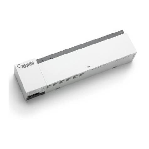
Wiring centre NEA H and NEA HC
Wiring centre for room temperature controllers, actuators and
timer.
Fig. 2-3 Wiring centre NEA H und NEA HC
Timer NEA
2-channel weekly timer.
Fig. 2-4 Timer NEA
Actuator
Thermal actuator with 230V AC or 24V AC supply voltage,
protection class IP54
Transformer 50VA
Safety transformer 230 V AC/24 V AC according EN 61558,
power 50 VA

SERVICE-MANUAL
ROOM TEMPERATURE CONTROLLER NEA 230V / 24V
7
2.2 Functional overview
NEA H NEA HT NEA HCT
Heating
Cooling
Temperature reduction by internal time switch programme
Temperature reduction by external “Timer NEA” possible
Display of current temperature
Display of current time and weekday
Setting of 3 timing programmes per day
Party and holiday mode
Integrated frost and valve exercise function
Switching of operating mode heating/cooling manually or externally
Remote temperature probe connectable

SERVICE-MANUAL
NEA ROOM CONTROLLER 230V / 24V
© REHAU
8
2.3 Technical data
NEA Room Controller
NEA 230 V NEA 24 V
Colour Front plate white (RAL 9016);
Back cover anthracite grey (RAL 7016)
Operating voltage 230 V, AC ±10 % 24 V, AC -10% / +20%
Max. switching current 0,2 A (resistive load) 1 A (resistive load)
Fuse T 0,63 A T 1 A
Safety Class II Class III
Max. number of actuators 5 thermal actuators
Degree of protection IP 30
Frost protection mode 5 °C
Dimensions, front 88 x 88 mm
Dimensions, rear 75 x 75 mm
Depth 26 mm
Storage temperature -20 – 60 °C
Ambient temperature 0 – 50 °C
Application In enclosed spaces
NEA Remote temperature probe
Sensor type NTC 10K (10 kOhm,1 % at 25 °C)
Cable length 4m
Protection class IP 67
NEA Timer
Operating voltage 230 V AC
Number of memory locations 84
Power reserve 10 years

SERVICE-MANUAL
NEA ROOM CONTROLLER 230V / 24V
© REHAU
9
NEA wiring centre
NEA wiring centre 230 V Heating
NEA wiring centre 24 V Heating, Heating und
Cooling
Colour
Lower housing and head section: dark grey similar RAL 7021;
cover: light grey similar RAL 7035
Operating voltage
230 V, AC
24 V, AC *)
Switch contact of pump relay **)
Potential free, relay, 230 V AC: 5A; 24 V DC: 1A
Fuse
T 4 A H
T 2 A
Safety
Class II
Class III
Maximum number of controllers
6
Max. number of actuators
12 thermal actuators
Number of terminals for timing
programmes ***)
2
Degree of protection
IP 20
Frost protection
5 °C
Dimensions, H x W x L
74 mm x 40 mm x 300 mm
Ambient temperature
0 – 60 °C
Humidity
Max. 80%, non-condensing
Application
In enclosed spaces
*) Transformer 50 VA for supply needed
**) only variant with pump relay
***) NEA Timer needed
Transformer 50 VA
Operating voltage
230 V AC
Output voltage
24 V AC
Power
50 VA
Dimensions W x H x D
68 mm x 70 mm x 75 mm
Other technical data
Safety transformer according EN 61558
Conditionally short-circuit proof with integrated overheating protection
Connecting cable (primary side) with moulded-in plug, length 100 cm
Cable on secondary side 30 cm
Mounting plate included, with clips for mounting rail

SERVICE-MANUAL
NEA ROOM CONTROLLER 230V / 24V
© REHAU
10
Actuator
Actuator 230 V
Actuator 24 V
Operating voltage
230 V, AC +10%... -10%, 50/60 Hz
24 V, AC, +20% … - 10%, 0 - 60 Hz
Inrush current
300 mA for max. 200 ms
250 mA for max. 2 min
Operating power
1,8 W
Version
Normally closed (NC)
Closing and opening times
approx. 3 min
Actuator travel
4 mm
Actuator power
100 N ±5 %
Ambient temperature
0 …. 60°C
Degree / class of protection
IP 54/II
Housing
Polyamide / grey
Connecting cable
2 x 0,75 mm², 1 m
Dimensions W x H x D
44 mm x 58 mm x 47 mm

SERVICE-MANUAL
NEA ROOM CONTROLLER 230V / 24V
© REHAU
11
3. Installation
3.1 System structure
Fig. 3-1 System structure NEA control system
1 – NEA room controller
2 - NEA Wiring centre
3 - Actuators
4 - Timer
5 – Remote temperature probe
The NEA room controller, the thermal actuators and the optional timer are connected to the NEA wiring centre.
The NEA wiring centre offers a safe and clear wiring of the system in the manifold cabinet.
The wiring centre allows up to 6 room temperature controllers and a maximum number of 12 actuators to be connected.
For the central control of the setback times the NEA timer can be used as an option.
A remote temperature probe can be connected to the NEA HCT room controllers.
Only wiring centres NEA HC and room temperature controllers NEA HCT may be used in heating/cooling applications!
A mixed use of room temperature controllers NEA HCT together with room temperature controllers NEA H or HT is not possible!
1
2
3
4
5

SERVICE-MANUAL
NEA ROOM CONTROLLER 230V / 24V
© REHAU
12
3.2 Wiring of NEA H and NEA HT room controllers to NEA H 230 V / 24 V wiring centre
Nea H / HT
N/L2
L/L1
A
B
230V 24V
L2
L1
N
L
230V 24V
L2
L1
N
L
N/L2
L/L1
A
B
optional
optional
wiring centre Nea
230 V AC
L N
24 V AC
L1 L2
Fig. 3-2 Wiring of NEA H and NEA HT room controllers to NEA H 230 V / 24 V wiring centre
Comment:
The connection of the reduced mode signal (clock symbol) is optional. The NEA wiring centre provides 2 time switch signals (A and B).
Each controller can be assigned to one of the time switch signals.
The time switch signals of the wiring centre are generated by NEA timer (2-channel weekly timer).
Triggering of reduced mode (Energy saving):
NEA H:
The external time switch signal is only valid, when the operating mode “time switch programme” is activated by the control buttons on the
controller.
When the controller is in normal operating mode or in reduced operating mode, the external signal is void.
NEA HT:
The same for NEA H room controller is valid, but in operating mode “time switch programme” the mode (normal/reduced) defined by the
internal time switch programme is overwritten by the external signal (Force of reduced mode).
See also parameter PE20.

SERVICE-MANUAL
NEA ROOM CONTROLLER 230V / 24V
© REHAU
13
3.3 Wiring of NEA H and NEA HT room controller without use of wiring centre
Nea H / HT L/L1 N/L2
230V 24V
L2
L1
N
L
230V 24V
L2
L1
N
L
maximum 5 !
optional
Fig. 3-3 Wiring of NEA H and NEA HT room controller without use of wiring centre
Note:
The signal for reduced mode has to be potential L (230V-systems) or L1 (24V-systems).
The signal may be generated by a timer or by a switching contact(common or for each separate controller).
In installations with more than one feed-in of operating voltage (e.g. several manifolds and therefore several wiring centres) phase
equality must be observed as soon as there is any electrical connection between the groups of control systems!

SERVICE-MANUAL
NEA ROOM CONTROLLER 230V / 24V
© REHAU
14
3.4 Wiring of NEA HCT room controllers to NEA HC 24 V wiring centre
Fig. 3-4 Wiring of NEA HCT room temperature controller to NEA HC 24 V wiring centre
Comment:
The CO signal is generated inside the wiring centre. As soon as the external switch connected to the shown pair of terminals is closed, the
connected controllers change to cooling mode.
Controllers which are not allowed to change to cooling mode (e.g. in bath rooms) have to be connected in the same way as shown in the
wiring diagram. Blocking of cooling mode is done by parameter PE9.
It is not provided to connect NEA H or NEA HT room controllers to a NEA HC 24V wiring centre. These controllers are only
designed for installations with solely heating mode and would have to be blocked in cooling mode by additional actions.

SERVICE-MANUAL
NEA ROOM CONTROLLER 230V / 24V
© REHAU
15
3.5 Wiring of NEA HCT room controllers without use of NEA HC 24 V wiring centre
Fig. 3-5 Wiring of NEA HCT room controllers without use of NEA HC 24 V wiring centre
Comment:
The signal for reduced mode and the signal for cooling mode have to be potential L1.
The signal for reduced mode may be generated by a timer or by a switching contact (common or for each controller separate).
In installations with more than one feed-in of operating voltage (e.g. several manifolds and therefore several wiring centres) phase
equality must be observed as soon as there is any electrical connection between the groups of control systems!

SERVICE-MANUAL
NEA ROOM CONTROLLER 230V / 24V
© REHAU
16
3.6 Use of dew point monitors
Dew point monitors must be fixed at the coldest point of the flow pipe. Ensure that the dew point monitor (DPM) is in sufficient contact with
the ambient air.
The DPM is installed as an opening contact in the line to the actuators, so that the activation is interrupted in case of condensation.
Fig. 3-6 Use of dew point monitors
Comment:
The diagram shows the dew point monitor TPW.
The maximum power consumption of the TPW is 1 VA; because of this the power supply 24 V of the wiring centre can be used.
The switching capacity of the TPW is 24V, 1A, and therefore sufficient for 5 actuators.

SERVICE-MANUAL
NEA ROOM CONTROLLER 230V / 24V
© REHAU
17
3.7 Wiring of NEA timer to NEA wiring centre
A
B
N/L2
L/L1
A
B
CO
L
N
!
17
65
43
28
wiring center Nea
Fig. 3-7 Wiring of NEA timer to NEA wiring centre
Please note that it is absolutely required to connect terminals 2 and 5 of NEA timer to the wiring centre in the shown way!
When terminals 3 and 6 of NEA timer are used, programming of the timer has to be done in such a way, that time periods with normal mode
are ON, the time periods with reduced mode are OFF.
The shown connection method is valid for all types of NEAwiring centres.

SERVICE-MANUAL
NEA ROOM CONTROLLER 230V / 24V
© REHAU
18
3.8 Wiring of a pump to NEA wiring centres with pump module
N/L2
L/L1
A
B
CO
A
B
L/L2
N/L1
L
N
PE
wiring center with option
„pump logic“
terminal box
Fig. 3-8 Wiring of a pump to NEA wiring centre with pump module
By connecting live mains voltage for pump supply to the wiring centre an external voltage is brought inside the wiring centre!
Note the maximum switching capacity of the pump relay in the wiring centre (5A 230 V AC, 1 A 24 V DC).
The shown connection method is valid for all types of NEAwiring centres with option “pump module”.

SERVICE-MANUAL
NEA ROOM CONTROLLER 230V / 24V
© REHAU
19
4. Parameterisation and special functions
4.1 Introduction
All parameters of the NEA room controllers are preset with values which are suitable for most applications. If necessary to customise the
parameterisation, please proceed carefully and note down allchanges.
You also have the possibility to reset all parameters and settings back to the factory settings by using parameter PE25.
4.2 Operating in service and expert level
Access:
-Activate display light by pressing any key and wait 2 seconds
-Press key and key for about 5 seconds simultaneously, until software version occurs
-Press Enter/Exit – key on the side
-Enter password “111” for service level or “314” for expert level using and - key
-Press Enter/Exit – key on the side to confirm
Navigation / change of parameters in service / expert-level:
-Navigate through list of parameters by using and key
-Select parameter to be changed with Enter/Exit key on the side
-The value to be changed flashes
-Value can be changed within the input limits usingthe and keys
-Confirm the value with Enter/Exit key on the side
-Leave service or expert level by pressing quickly Enter/Exit key twice (double click)

SERVICE-MANUAL
NEA ROOM CONTROLLER 230V / 24V
© REHAU
20
4.3 Service level
Access with password 111
Para-
meter
Description
Comment
Default
Min.-
value
Max.-
value
NEA
H
NEA
HT
NEA
HCT
PS01
Enable set point
change
Defines whether temperature set point can be
changed by control buttons
ON
OFF
ON
PS02
Enable change of
operating mode
Defines whether operating mode (nor-
mal/reduced/time switch programme/Off) can
be changed by control buttons
ON
OFF
ON
PS03
Enable OFF-mode
Defines whether the controller can be set to
OFF-mode
OFF
OFF
ON
PS04
Enable Party /
presence - function
0: Party/presence-function blocked
1: presence-function enabled
2: Party function with free choice of duration
enabled
3: Party function with choice between
30, 60, 90, 120, ….300 minutes
enabled, preset 60 min
2
0
3
PS05
Enable change of
time switch
programme
Defines whether the preset timing programme
is allowed to be changed
ON
OFF
ON
PS06
Enable clock setting
Defines whether clock can be set
ON
OFF
ON
PS07
Enable date setting
Defines whether date can be set
ON
OFF
ON
PS08
Enable holiday mode
Defines whether holiday function can be
enabled
ON
OFF
ON
PS09
Activation key lock
Keys are locked after 30 min. (lock is shown
on display when any key is pressed).
See note *1) how to release keys temporarily
OFF
OFF
ON
PS10
Temperature unit
(°C/F)
ON: Display in °C
OFF: Display in Fahrenheit
ON
OFF
ON
PS11
Clock format
(24h/12h)
ON: 24h – Format
OFF: 12h – Format (AM / PM)
ON
OFF
ON
PS12
Display light mode
0: Off
1: permanent on
2: Auto: on by key press, automatic switch off
with delay
2
0
2
*1) Press all 3 keys at the same time for about 3 seconds, enter password 410
Key lock will be overruled for 30 mins, in this timeframe parameter PS09 can be set back

SERVICE-MANUAL
NEA ROOM CONTROLLER 230V / 24V
© REHAU
21
Para-
meter
Description
Comment
Default
Min.-
value
Max.-
value
NEA
H
NEA
HT
NEA
HCT
PS13
Automatic
acceptance of
changed values
ON: Changed values will be accepted,
when Enter/Exit Key is pressed and after
5 sec.
OFF: Changed values will be accept
ed only,
when Enter/Exit Key is pressed. If not, the
input will be cancelled.
ON
OFF
ON
PS14
Set point heating
reduced mode
Room temp. set point for heating mode in
reduced mode [°C]
18
0
37
PS15
Set point heating
normal mode
Room temp. set point for heating mode in
normal mode [°C]
22
0
37
PS16
Set point cooling
normal mode
Room temp. set point for cooling mode in
normal mode [°C]
24
0
37
PS17
Set point cooling
reduced mode
Room temp. set point for cooling mode in
reduced mode [°C]
26
0
37
PS18
Resolution of set
point and actual value
reading
0: values will be displayed with 1K reading
1: 0,5K reading
2: 0,1K reading
1
0
2
PS19
Calibration of internal
temperature probe
Offset value for internal room temperature
probe
0K
-5K
+5K
PS20
Calibration of external
temperature probe
Offset value for external temperature probe /
floor temperature probe
0K
-5K
+5K
PS21
Actual value of
external temperature
probe
Display of actual temperature value from
external temperature probe
-
0°C
50°C
PS22
State of switching
output
The state of switching output for actuator is
shown (ON/OFF).
Comment:
The state of output is also displayed in end
user level with the “heating” or “cooling”
symbol.
-
OFF
ON
PS23
Number of connected
actuators
Only 24V controllers:
Number of actuators directly connected to
switching output
1
1
5
Other manuals for NEA
3
Table of contents
Other Rehau Temperature Controllers manuals