manuals.online logo
Brands
  1. Home
  2. •
  3. Brands
  4. •
  5. RELCO
  6. •
  7. Lighting Equipment
  8. •
  9. RELCO 65151IP67CP1 User manual

RELCO 65151IP67CP1 User manual

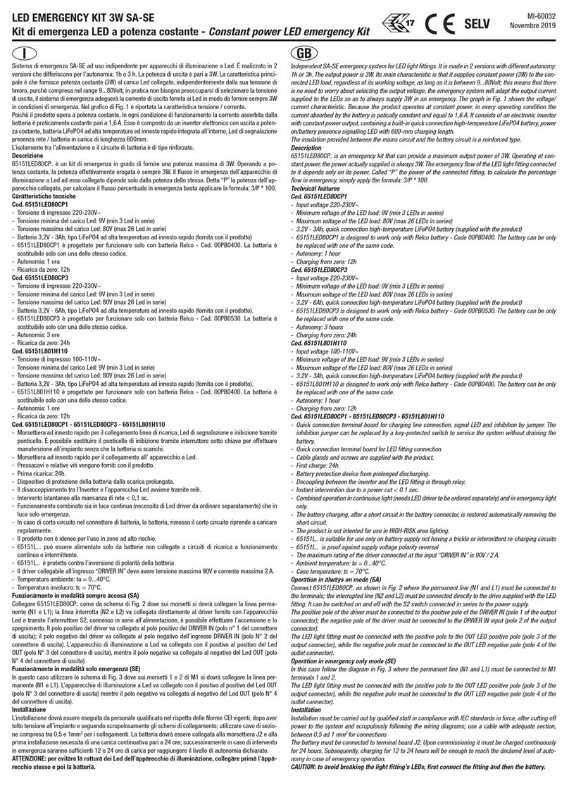
LED EMERGENCY KIT 3W SA-SE IP67
Kit di emergenza LED a potenza costante - Constant power LED emergency Kit
MI-60035
Novembre 2020
I
Sistema di emergenza SA-SE ad uso indipendente per apparecchi di illuminazione a Led. É realizzato in 2
versioni che differiscono per l’autonomia: 1h o 3 h. La potenza di uscita è pari a 3W. La caratteristica princi-
pale è che fornisce potenza costante (3W) al carico Led collegato, indipendentemente dalla sua tensione di
lavoro, purchè compresa nel range 9...80Volt; in pratica non bisogna preoccuparsi di selezionare la tensione
di uscita, il sistema di emergenza adeguerà la corrente di uscita fornita ai Led in modo da fornire sempre 3W
in condizioni di emergenza. Nel grafico di Fig. 1 è riportata la caratteristica tensione / corrente.
Poichè il prodotto opera a potenza costante, in ogni condizione di funzionamento la corrente assorbita dalla
batteria è praticamente costante pari a 1,6 A. Esso è composto da un inverter elettronico con uscita a poten-
za costante, batteria LiFePO4 ad alta temperatura ed innesto rapido integrata all’interno, Led di segnalazione
presenza rete / batteria in carica di lunghezza 600mm.
L’isolamento tra l’alimentazione e il circuito di batteria è di tipo rinforzato.
Descrizione
Kit di emergenza in grado di fornire una potenza massima di 3W. Operando a potenza costante, la potenza
effettivamente erogata è sempre 3W. Il flusso in emergenza dell’apparecchio di illuminazione a Led ad
esso collegato dipende solo dalla potenza dello stesso. Detta “P” la potenza dell’apparecchio collegato, per
calcolare il flusso percentuale in emergenza basta applicare la formula: 3/P * 100.
Caratteristiche tecniche
Cod. 65151IP67CP1
- Tensione di ingressso 220-230V~
- Tensione minima del carico Led: 9V (min 3 Led in serie)
- Tensione massima del carico Led: 80V (max 26 Led in serie)
- Batteria 3,2V - 3Ah, tipo LiFePO4 ad alta temperatura ad innesto rapido (fornita con il prodotto)
- Progettato per funzionare solo con batteria Relco - Cod. 00PB0400. La batteria è sostituibile solo con una
dello stesso codice.
- Autonomia: 1 ora
- Ricarica da zero: 12h
Cod. 65151IP67CP3
- Tensione di ingressso 220-230V~
- Tensione minima del carico Led: 9V (min 3 Led in serie)
- Tensione massima del carico Led: 80V (max 26 Led in serie)
- Batteria 3,2V - 6Ah, tipo LiFePO4 ad alta temperatura ad innesto rapido (fornita con il prodotto).
- Progettato per funzionare solo con batteria Relco - Cod. 00PB0530. La batteria è sostituibile solo con una
dello stesso codice.
- Autonomia: 3 ore
- Ricarica da zero: 24h
Cod. 65151IP67CP1 - 65151IP67CP3
- Morsettiera ad innesto rapido per il collegamento linea di ricarica, Led di segnalazione e inibizione tramite
ponticello. É possibile sostituire il ponticello di inibizione tramite interruttore sotto chiave per effettuare
manutenzione all’impianto senza che la batteria si scarichi.
- Morsettiera ad innesto rapido per il collegamento all’ apparecchio a Led.
- Pressacavi e relative viti vengono forniti con il prodotto.
- Prima ricarica: 24h.
- Dispositivo di protezione della batteria dalla scarica prolungata.
- Il disaccoppiamento tra l’Inverter e l’apparecchio Led avviene tramite relè.
- Intervento istantaneo alla mancanza di rete < 0,1 sc.
- Funzionamento combinato sia in luce continua (necessita di Led driver da ordinare separatamente) che in
luce solo emergenza.
- In caso di corto circuito nel connettore di batteria, la batteria, rimosso il corto circuito riprende a caricare
regolarmente.
- Il prodotto non è idoneo per l’uso in zone ad alto rischio.
- 65151IP67... può essere alimentato solo da batterie non collegate a circuiti di ricarica a funzionamento
continuo o intermittente.
- 65151IP67... è protetto contro l’inversione di polarità della batteria
- Il driver collegabile all’ingresso “DRIVER IN” deve avere tensione massima 90V e corrente massima 2 A.
- Temperatura ambiente: ta = 0...40°C.
- Temperatura involucro: tc = 70°C.
Funzionamento in modalità sempre accesa (SA)
Collegare 65151IP67.. come da schema di Fig. 2 dove sui morsetti si dovrà collegare la linea permanente
(N1 e L1); la linea interrotta (N2 e L2) va collegata direttamente al driver fornito con l’apparecchio Led e
tramite l’interruttore S2, connesso in serie all’alimentazione, è possibile effettuare l’accensione e lo spe-
gnimento. Il polo positivo del driver va collegato al polo positivo del DRIVER IN (polo n° 1 del connettore
di uscita); il polo negativo del driver va collegato al polo negativo dell’ingresso DRIVER IN (polo N° 2 del
connettore di uscita). L’apparecchio di illuminazione a Led va collegato con il positivo al positivo del Led
OUT (polo N° 3 del connettore di uscita), mentre il polo negativo va collegato al negativo del Led OUT (polo
N° 4 del connettore di uscita)
Funzionamento in modalità solo emergenza (SE)
In questo caso utilizzare lo schema di Fig. 3 dove sui morsetti 1 e 2 di M1 si dovrà collegare la linea per-
manente (N1 e L1). L’apparecchio di illuminazione a Led va collegato con il positivo al positivo del Led OUT
(polo N° 3 del connettore di uscita) mentre il polo negativo va collegato al negativo del Led OUT (polo N° 4
del connettore di uscita).
Installazione
L’installazione dovrà essere eseguita da personale qualificato nel rispetto delle Norme CEI vigenti, dopo aver
tolto tensione all’impianto e seguendo scrupolosamente gli schemi di collegamento; utilizzare cavo di sezio-
ne compresa tra 0,5 e 1mm2per i collegamenti. La batteria dovrà essere collegata alla morsettiera J2 e alla
prima installazione necessita di una carica continuativa pari a 24 ore; successivamente in caso di intervento
in emergenza saranno sufficienti 12 o 24 ore di carica per raggiungere il livello di autonomia dichiarato.
ATTENZIONE: per evitare la rottura dei Led dell’apparecchio di illuminazione, collegare prima l’appa-
recchio stesso e poi la batteria.
GB
Independent SA-SE emergency system for LED light fittings. It is made in 2 versions with different autonomy:
1h or 3h. The output power is 3W. Its main characteristic is that it supplies constant power (3W) to the con-
nected LED load, regardless of its working voltage, as long as it is between 9...80Volt; this means that there
is no need to worry about selecting the output voltage, the emergency system will adapt the output current
supplied to the LEDs so as to always supply 3W in an emergency. The graph in Fig. 1 shows the voltage/
current characteristic. Because the product operates at constant power, in every operating condition the
current absorbed by the battery is patically constant and equal to 1,6 A. It consists of an electronic inverter
with constant power output, containing a built-in quick connection high-temperature LiFePO4 battery,power
on/battery presence signalling LED with 600-mm charging length.
The insulation provided between the mains circuit and the battery circuit is a reinforced type.
Description
Emergency kit that can provide a maximum output power of 3W. Operating at constant power, the power
actually supplied is always 3W. The emergency flow of the LED light fitting connected to it depends only
on its power. Called “P” the power of the connected fitting, to calculate the percentage flow in emergency,
simply apply the formula: 3/P * 100.
Technical features
Cod. 65151IP67CP1
- Input voltage 220-230V~
- Minimum voltage of the LED load: 9V (min 3 LEDs in series)
- Maximum voltage of the LED load: 80V (max 26 LEDs in series)
- 3.2V - 3Ah, quick connection high-temperature LiFePO4 battery (supplied with the product)
- Designed to work only with Relco battery - Code 00PB0400. The battery can be only be replaced with one
of the same code.
- Autonomy: 1 hour
- Charging from zero: 12h
Cod. 65151IP67CP3
- Input voltage 220-230V~
- Minimum voltage of the LED load: 9V (min 3 LEDs in series)
- Maximum voltage of the LED load: 80V (max 26 LEDs in series)
- 3.2V - 6Ah, quick connection high-temperature LiFePO4 battery (supplied with the product)
- Designed to work only with Relco battery - Code 00PB0530. The battery can be only be replaced with one
of the same code.
- Autonomy: 3 hours
- Charging from zero: 24h
Cod. 65151IP67CP1 - 65151IP67CP3
- Quick connection terminal board for charging line connection, signal LED and inhibition by jumper. The
inhibition jumper can be replaced by a key-protected switch to service the system without draining the
battery.
- Quick connection terminal board for LED fitting connection.
- Cable glands and screws are supplied with the product.
- First charge: 24h.
- Battery protection device from prolonged discharging.
- Decoupling between the inverter and the LED fitting is through relay.
- Instant intervention due to a power cut < 0.1 sec.
- Combined operation in continuous light (needs LED driver to be ordered separately) and in emergency light
only.
- The battery charging, after a short circuit in the battery connector, is restored automatically removing the
short circuit.
- The product is not intented for use in HIGH-RISK area lighting.
- 65151IP67.. is suitable for use only on battery supply not having a trickle or intermittent re-charging
circuits
- 65151IP67.. is proof against supply voltage polarity reversal
- The maximum rating of the driver connected at the input “DRIVER IN” is 90V / 2 A.
- Ambient temperature: ta = 0...40°C.
- Case temperature: tc = 70°C.
Operation in always on mode (SA)
Connect 65151IP67.. as shown in Fig. 2 where the permanent line (N1 and L1) must be connected to the
terminals; the interrupted line (N2 and L2) must be connected directly to the drive supplied with the LED
fitting. It can be switched on and off with the S2 switch connected in series to the power supply.
The positive pole of the driver must be connected to the positive pole of the DRIVER IN (pole 1 of the output
connector); the negative pole of the driver must be connected to the DRIVER IN input (pole 2 of the output
connector).
The LED light fitting must be connected with the positive pole to the OUT LED positive pole (pole 3 of the
output connector), while the negative pole must be connected to the OUT LED negative pole (pole 4 of the
outlet connector).
Operation in emergency only mode (SE)
In this case follow the diagram in Fig. 3 where the permanent line (N1 and L1) must be connected to M1
terminals 1 and 2.
The LED light fitting must be connected with the positive pole to the OUT LED positive pole (pole 3 of the
output connector), while the negative pole must be connected to the OUT LED negative pole (pole 4 of the
outlet connector).
Installation
Installation must be carried out by qualified staff in compliance with IEC standards in force, after cutting off
power to the system and scrupulously following the wiring diagrams; use a cable with adequate section,
between 0,5 ad 1 mm2 for connections
The battery must be connected to terminal board J2. Upon commissioning it must be charged continuously
for 24 hours. Subsequently, charging for 12 to 24 hours will be enough to reach the declared level of auto-
nomy in case of emergency operation.
CAUTION: to avoid breaking the light fitting’s LEDs, first connect the fitting and then the battery.
F
Système d’urgence SA-SE à usage indépendant pour appareils d’éclairage à LED. Il est réalisé en 2 versions
qui diffèrent pour l’autonomie : 1h ou 3h. La puissance de sortie est égale à 3W. La caractéristique principale
est qu’il fournit une puissance constante (3W) à la charge de la LED raccordée, indépendamment de sa
tension de fonctionnement, sous réserve qu’elle soit comprise dans la plage 9...80 Volts ; en pratique il ne
faut pas se préoccuper de sélectionner la tension de sortie, le système d’urgence adaptera le courant de
sortie fourni aux LED afin de toujours fournir 3W en conditions d’urgence.
Sur le graphique de la Fig. 1 est reportée la caractéristique tension/courant.
Il est composé d’un Inverter électronique avec une sortie à puissance constante, d’une batterie LiFePO4 à
haute température et un raccord rapide intégrée à l’intérieur et d’une LED de signalisation de présence de
réseau/batterie en cours de charge de 600 mm de long.
L’isolation entre l’alimentation et la batterie est renforcée.
Description
Kit d’urgence en mesure de fournir une puissance maximale de 3 W. En opérant à puissance constante, la
puissance effectivement distribuée est toujours 3W. Le flux en urgence de l’appareil d’éclairage à LED qui y
IP67 SELV
est raccordé dépend uniquement de la puissance de ce dernier.
« P » est la puissance de l’appareil raccordé, pour calculer le flux en pourcentage en urgence il suffit d’ap-
pliquer la formule : 3/P * 100.
Caractéristiques techniques
Cod. 65151IP67CP1
- Tension d’entrée 220-230V ~
- Tension minimum de la charge LED : 9V (min 3 LED en série)
- Tension maximum de la charge LED : 80V (max 26 LED en série)
- Batterie 3,2V - 3Ah, type LiFePO4 à haute température avec raccord rapide (fourni avec le produit).
- Conçu pour fonctionner uniquement avec la batterie Relco - Code 00PB0400. La batterie n’est
remplaçable que par une du même code
- Autonomie : 1 heure
- Recharge à partir de zéro : 12 h
Cod. 65151IP67CP3
- Tension d’entrée 220-230V ~
- Tension minimum de la charge LED : 9V (min 3 LED en série)
- Tension maximum de la charge LED : 80V (max 26 LED en série)
- Batterie 3,2 V 6Ah, type LiFePO4 à haute température avec raccord rapide (fourni avec le produit).
- Conçu pour fonctionner uniquement avec la batterie Relco - Code 00PB0530. La batterie n’est
remplaçable que par une du même code.
- Autonomie : 3 heures
- Recharge à partir de zéro : 24 h
Cod. 65151IP67CP1 - 65151IP67CP3
- Barrette de raccordement à raccord rapide pour le raccordement à la ligne de recharge, LED de
signalisation et d’inhibition par cavalier. Il est possible de remplacer le cavalier d’inhibition par un
interrupteur à clé pour effectuer l’entretien à l’installation sans que la batterie ne se décharge.
- Barrette de raccordement à raccord rapide pour le raccordement à l’appareil à LED.
- Serre-câbles et ses vis fournies avec le produit.
- Première recharge : 24 h.
- Dispositif de protection de la batterie contre la décharge prolongée.
- Le découplage entre l’Inverter et l’appareil LED se fait par relais.
- Intervention instantanée en cas de manque de réseau < 0,1 s.
- Fonctionnement combiné aussi bien en lumière continue (nécessité de LED driver à commander
séparément) qu’en éclairage d’urgence uniquement.
- Température ambiante : ta = 0…+50 °C.
- Température du boîtier : Tc = 70 °C.
Fonctionnement en mode toujours allumé (TA)
Raccorder 65151IP67... comme sur le schéma de la Fig. 2 où il faudra raccorder sur les bornes la ligne
permanente (N1 et L1) ; la ligne interrompue (N2 et L2) doit être raccordée directement au driver fourni avec
l’appareil LED et au moyen de l’interrupteur S2, connecté en série à l’alimentation, il est possible d’effectuer
l’allumage et l’arrêt.
Le pôle positif du driver doit être raccordé au pôle positif du DRIVER IN (pôle n° 1 du connecteur de sortie);
le pôle négatif du driver doit être raccordé au pôle négatif de l’entrée DRIVER IN (pôle N° 2 du connecteur
de sortie).
L’appareil d’éclairage à LED doit être raccordé avec le positif au positif du LED OUT (pôle N° 3 du connecteur
de sortie), alors que le pôle négatif doit être raccordé au négatif du LED OUT (pôle N° 4 du connecteur de
sortie)
Fonctionnement en mode urgence uniquement (UE)
Dans ce cas, utiliser le schéma de la Fig. 3 où il faudra raccorder sur les bornes 1 et 2 de M1 la ligne
permanente (N1 et L1).
L’appareil d’éclairage à LED doit être raccordé avec le positif au positif du LED OUT (pôle N° 3 du connecteur
de sortie) alors que le pôle négatif doit être raccordé au négatif du LED OUT (pôle N° 4 du connecteur de
sortie).
Installation
L’installation doit être effectuée par un personnel qualifié en respectant les normes CEI en vigueur, après
avoir coupé le courant sur l’installation, et en suivant scrupuleusement les schémas de connexion ; utiliser
un câble d’une section comprise entre 0,5 et 1 mm2pour les connexions.
La batterie doit être raccordée à la barrette de raccordement J2 et, à la première installation, elle requiert
une charge continue de 24 heures, par la suite, en cas d’intervention en urgence 12 ou 24 heures de charge
seront suffisantes pour atteindre le niveau d’autonomie déclaré.
ATTENTION : pour éviter la rupture des LED de l’appareil d’éclairage, raccorder d’abord l’appareil en
question et ensuite la batterie.
D
Unabhängiges Notsystem SA-SE für LED-Beleuchtungsgeräte. Das System steht in 2 Versionen zur Wahl,
die sich durch ihre Autonomie unterscheiden: 1 Stunde oder 3 Stunden. Die Ausgangsleistung beträgt 3
W. Das Hauptmerkmal dieses Systems ist die Ausgabe einer konstanten Leistung (3W) an die verbundene
LED-Last, unabhängig von der Betriebsspannung, sofern sie im Bereich 9...80 Volt liegt; dies bedeutet, dass
die Ausgangsspannung nicht getrennt werden muss, das Notbeleuchtungssystem passt den von den LEDs
gelieferte Ausgangsstrom so an, dass auch in Notsituationen immer 3W abgegeben werden.
In der Grafik in Abb. 1 sind die Merkmale Spannung / Strom angegeben.
Das System besteht aus einem elektronischen Inverter mit konstant stromführendem Ausgang, einer
Hochtemperatur-LiFePO4-Batterie mit integriertem Schnellanschluss, einer 600 mm langen LED-Meldevor-
richtung für Netzspannung vorhanden/Batterie wird geladen.
Die Isolation zwischen Netzteil und Batterie ist verstärkt.
Beschreibung
Notbeleuchtungsgerät, das eine maximale Leistung von 3W abgeben kann. Durch den Betrieb in Kon-
stantstrom beträgt die tatsächliche Leistung immer 3W. Der Lichtstrom im Notbetrieb des LED-Be-
leuchtungsgeräts hängt nur von seiner Leistung ab.
Zur Berechnung des prozentualen Lichtstroms im Notbetrieb genügt es, folgende Formel anzuwenden, wo-
bei die Leistung des verbundenen Geräts „P“ genannt wird: 3/P * 100.
Technische Eigenschaften
Cod. 65151IP67CP1
- Eingangsspannung 220-230V ~
- Mindestspannung der LED-Last: 9V (min. 3 reihengeschaltete LEDs)
- Höchstspannung der LED-Last: 80V (max. 26 reihengeschaltete LEDs)
- Batterie 3,2V - 3Ah, Hochtemperatur-LiFePO4 mit Schnellanschluss, der dem Produkt beigestellt ist
- Entwickelt, um nur mit Relco-Batterie zu arbeiten - Code 00PB0400. Die Batterie ist nur durch eine
austauschbar des gleichen Codes
- Betriebszeit mit Batterie: 1 Stunde
- Laden aus Leerzustand: 12 Stunden
Cod. 65151IP67CP3
- Eingangsspannung 220-230V ~
- Mindestspannung der LED-Last: 9V (min. 3 reihengeschaltete LEDs)
- Höchstspannung der LED-Last: 80V (max. 26 reihengeschaltete LEDs)
- Batterie 3,2V - 6Ah, Hochtemperatur-LiFePO4 mit Schnellanschluss, der dem Produkt beigestellt ist.
- Entwickelt, um nur mit Relco-Batterie zu arbeiten - Code 00PB0530. Die Batterie ist nur durch eine
austauschbar des gleichen Codes.
- Betriebszeit mit Batterie: 3 Stunden
- Laden aus Leerzustand: 24 h
Cod. 65151IP67CP1 - 65151IP67CP3
- Klemmbrett mit Schnellanschluss für die Verbindung mit der Linie zum Aufladen, Melde-LED und
Sperrung über Überbrückung. Die Überbrückung für die Sperrung kann durch einen verriegelten Schalter
ersetzt werden, um Wartungsarbeiten an der Anlage auszuführen, ohne dass die Batterie entladen wird.
- Klemmbrett mit Schnellanschluss für die Verbindung mit dem LED-Gerät.
- Kabelverschraubung und entsprechende Schrauben werden mit dem Produkt mitgeliefert.
- Erstes Laden: 24 Stunden
- Vorrichtung zum Schutz der Batterie gegen langes Entladen.
- Die Entkopplung des Inverters vom LED-Beleuchtungsgerät erfolgt über Relais.
- Sofortige Auslösung bei Ausfall der Netzspannung < 0,1 s.
- Kombinierte Funktionsweise sowohl bei Dauerlicht (bedarf eines Drivers, der separat zu bestellen ist) als
bei Notbeleuchtung.
- Raumtemperatur: ta = 0...50 °C.
- Gehäusetemperatur: tc = 70 ºC.
Betrieb im Modus immer eingeschaltet (SA)
65151IP67... gemäß Schaltplan in Abb. 2 verbinden, wo an den Klemmen die Dauerstrom-Leitung angesch-
lossen werden muss (N1 und L1); die unterbrochene Linie (N2 und L2) muss direkt an den mit dem LED-
Beleuchtungsgerät mitgelieferten Driver angeschlossen werden, und mit dem reihengeschalteten Schalter
S2 kann ein- /ausgeschaltet werden.
Der Pluspol des Drivers muss mit dem Pluspol am DRIVER IN (Pol Nr. 1 des ausgehenden Verbinders) ver-
bunden werden; der Minuspol Drivers muss mit dem Minuspol des Eingangs DRIVER IN (Pol Nr 2. des
ausgehenden Verbinders) verbunden werden.
Das LED-Beleuchtungsgerät muss mit dem Pluspol am Pluspol des LED OUT (Pol Nr. 3 des ausgehenden
Verbinders) verbunden werden, der Minuspol muss mit dem Minuspol LED OUT (Pol Nr. 4 des ausgehenden
Verbinders) verbunden werden
Betrieb im Modus nur Notbeleuchtung (SE)
In diesem Fall muss der Schaltplan auf Abb. 3 verwendet werden, wobei an den Klemmen 1 und 2 von M1
die Dauerstrom-Leitung (N1 und L1) angeschlossen werden muss.
Das LED-Beleuchtungsgerät muss mit dem Pluspol am Pluspol des LED OUT (Pol Nr. 3 des ausgehenden
Verbinders) verbunden werden, der Minuspol muss mit dem Minuspol LED OUT (Pol Nr. 4 des ausgehenden
Verbinders) verbunden werden.
Installation
Die Installation ist durch qualifiziertes Personal unter Einhaltung der geltenden IEC-Normen, nach Abtrennen
der Anlage von der Stromversorgung durchzuführen. Dabei sind die Anschlusspläne streng zu befolgen und
ist ein Kabel mit einem Querschnitt zwischen 0,5 und 1mm2für den Anschluss.
Die Batterie ist an Klemmleiste J2 anzuschließen. Bei der Erstinstallation muss sie 24 Stunden lang unun-
terbrochen geladen werden, danach genügen, im Falle von Notauslösung, 12 oder 24 Stunden Laden, um
die angegebene Autonomie zu erreichen.
ACHTUNG: Um den Bruch der LEDs des Beleuchtungsgeräts zu verhindern, zuerst das Gerät und
anschließend die Batterie anschließen.
ES
Sistema de emergencia SA-SE de uso independiente para aparatos de iluminación mediante Led. Se ha rea-
lizado en 2 versiones que difieren por lo que se refiere a la autonomía: 1 h o 3 h. La potencia de salida es de
3 W. La característica principal es que proporciona potencia constante (3 W) a la carga Led conectada, inde-
pendientemente de su tensión de trabajo, aunque comprendida en un rango de 9...80 Voltios; en la práctica,
no hay que preocuparse de seleccionar la tensión de salida, el sistema de emergencia adecuará la corriente
de salida proporcionada a los Led a fin de proporcionar siempre 3 W en condiciones de emergencia.
En el gráfico de la Fig. 1 se muestra la característica tensión / corriente.
Está compuesto por un inversor electrónico con salida de potencia, constante, una batería LiFePO4 de alta
temperatura con acoplamiento rápido, incorporada en el interior y Led de señalización de presencia de red/
batería bajo carga de 600 mm de longitud.
El aislamiento entre la fuente de alimentación y la batería está reforzado..
Descripción
Kit de emergencia que proporciona una potencia máxima de 3 W. Trabajando a potencia constante, la po-
tencia suministrada efectivamente es siempre de 3 W. El flujo en emergencia del aparato de iluminación por
Led conectado al mismo depende solo de la potencia del mismo.
Denominada «P» la potencia del aparato conectado, para calcular el flujo porcentual en emergencia es
suficiente aplicar la fórmula: 3/P * 100.
Características técnicas
Cod. 65151IP67CP1
- Voltaje de entrada 220-230V ~
- Tensión mínima de la carga Led: 9 V (mín. 3 Led en serie)
- Tensión máxima de la carga Led: 80 V (máx. 26 Led en serie)
- Batería 3,2 V - 3 Ah, tipo LiFePO4 de alta temperatura de acoplamiento rápido (suministrada con el
producto).
- Diseñado para funcionar solo con batería Relco - Código 00PB0400. La batería solo se puede reemplazar
por una del mismo código
- Autonomía: 1 horas
- Recarga desde cero: 12 h
Cod. 65151LED80CP3
- Voltaje de entrada 220-230V ~
- Tensión mínima de la carga Led: 9 V (mín. 3 Led en serie)
- Tensión máxima de la carga Led: 80 V (máx. 26 Led en serie)
- Batería 3,2 V - 3 Ah, tipo LiFePO4 de alta temperatura de acoplamiento rápido (suministrada con el
producto).
- Diseñado para funcionar solo con batería Relco - Código 00PB0530. La batería solo se puede reemplazar
por una del mismo código.
- Autonomía: 3 horas
- Recarga desde cero: 24 h
Cod. 65151IP67CP1 - 65151IP67CP3
- Regleta de bornes con acoplamiento rápido para la conexión de la línea de recarga, Led de señalización
e inhibición mediante puente. Se puede sustituir el puente de inhibición interviniendo en el interruptor bajo
llave para realizar el mantenimiento de la instalación sin descargar la batería.
- Regleta de bornes con acoplamiento rápido para la conexión con el aparato de Led.
- Los prensacables y los correspondientes tornillos se suministran con el producto.
- Primera recarga: 24 h
- Dispositivo de protección de la batería contra la descarga prolongada.
- El desacoplamiento entre el inversor y el aparato de Led tiene lugar mediante un relé.
- Intervención instantánea cuando falta la red < 0,1 s.
- Funcionamiento combinado tanto de luz continua (necesita Led driver que hay que pedir por separado)
como de luz de emergencia.
- Temperatura ambiente: ta = 0…50 °C.
- Temperatura del revestimiento: tc = 70°C.
Funcionamiento en modo siempre encendido (SA)
Conecte 65151IP67... tal como se indica en el esquema de la Fig. 2, donde en los bornes habrá que conec-
tar la línea permanente (N1 y L1); la línea interrumpida (N2 y L2) ha de conectarse directamente al driver
suministrado con el aparato de Led, y mediante el interruptor S2, conectado en serie a la alimentación, es
posible proceder al encendido y al apagado.
El polo positivo del driver debe conectarse al polo positivo del DRIVER IN (polo n.º 1 del conector de salida);
el polo negativo del driver debe conectarse al polo negativo de la entrada DRIVER IN (polo n.º 2 del conector
de salida).
El aparato de iluminación por Led ha de conectarse con el positivo al positivo del Led OUT (polo N.º 3 del
conector de salida), mientras que el polo negativo ha de conectarse al negativo del Led OUT (polo N.º 4 del
conector de salida).
Funcionamiento en modo solo emergencia (SE)
En este caso, utilice el esquema de la Fig. 3 donde en los bornes 1 y 2 de M1 habrá que conectar la línea
permanente (N1 y L1).
El aparato de iluminación por Led ha de conectarse con el positivo al positivo del Led OUT (polo N.º 3 del
conector de salida), mientras que el polo negativo debe conectarse al negativo del Led OUT (polo N.º 4 del
conector de salida).
Instalación
La instalación deberá ser llevada a cabo por personal cualificado respetando las Normas CEI vigentes, tras
haber dejado sin tensión la instalación y siguiendo escrupulosamente los esquemas de conexión; utilice un
cable con una sección comprendida entre 0,5 y 1mm2para las conexiones.
La batería debe conectarse a la regleta de bornes J2; cuando se instala por primera vez, requiere una carga
continuada de 24 horas; después, en caso de intervención en emergencia, serán suficientes 12 o 24 horas
de carga para alcanzar la autonomía declarada.
ATENCIÓN: para evitar la rotura de los Led del aparato de iluminación, conecte primero esté último
y después la batería.
DK
Nødsystem SA-SE til belysningsarmaturer med LED. Udført i to udgaver med forskellig rækkevidde: 1 eller
3 timer. Udgangseffekten er på 3W. Systemets primære funktion er, at levere konstant effekt (3W) til den
tilsluttede LED-enhed uanset driftsspændingen, så længe den ligger i området 9... 80 Volt. I praksis behøver
du ikke bekymre dig om valget af udgangsspænding, nødsystemet vil justere den udgangsstrøm, der leveres
til LED-enhederne, for altid at levere 3W i nødsituationer.
På figur 1 vises karakteristika for spænding / strøm.
Den består af en elektronisk inverter med konstant effektudgang, FeP04 batteri ved høj temperatur og inte-
greret intern hurtigkobling, led til signalering af tilstedeværelsen af strømforsyning / batteri under opladning,
længde 600 mm.
Isolationen mellem strømforsyningen og batteriet er forstærket.
Beskrivelse
Nødsystem, der kan levere en maksimum effekt på 3W. Ved drift med konstant effekt, er den faktiske
leverede effekt altid 3W. Nødstrømmen der tilføres det tilsluttede belysningsarmatur med LED, afhænger
kun af effekten.
Det såkaldte “P” der angiver effekten for den tilsluttede enhed, anvendes til at beregne den procentvise
strøm i nødsituationer, ved hjælp af formlen: 3/P * 100.
Tekniske karakteristika
Cod. 65151IP67CP1
- Indgangsspænding 220-230V ~
- Minimumsspænding for LED-enheden: 9V (min 3 Led i serie)
- Maksimumsspænding for LED-enheden: 80V (min 26 Led i serie)
- Batteri 3,2V 3Ah, type LiFePO4 ved høj temperatur med hurtigkobling (leveret med produktet).
- Designet til kun at arbejde med Relco-batteri - Kode 00PB0400. Batteriet kan kun udskiftes med et af
den samme kode
- Autonomi: 1 time
- Opladning fra nul: 12t
Cod. 65151IP67CP3
- Indgangsspænding 220-230V ~
- Minimumsspænding for LED-enheden: 9V (min 3 Led i serie)
- Maksimumsspænding for LED-enheden: 80V (min 26 Led i serie)
- Batteri 3,2V - 6Ah, type LiFePO4 ved høj temperatur med hurtigkobling (leveret med produktet).
- Designet til kun at arbejde med Relco-batteri - Kode 00PB0530. Batteriet kan kun udskiftes med et af
den samme kode.
- Autonomi: 3 timer
- Opladning fra nul: 24t
Cod. 65151IP67CP1 - 65151IP67CP3
- Terminal med hurtigkobling for tilslutning til linjen for opladning, signal-LED og inhalering via jumper.
Det er muligt at udskifte inhiberingsjumperen via aflåst kontakt, for at udføre vedligeholdelse på anlægget
uden at batteriet aflades.
- Terminal med hurtigkobling for tilslutning til LED-enheden.
- Kabelmuffer og relative skruer leveres med produktet.
- Første opladning: 24t.
- Enhed til beskyttelse af batteriet mod langvarig afladning.
- Frakoblingen mellem inverteren og LED-apparatet foregår via et relæ.
- Øjeblikkelig aktivering ved manglende strøm på netværket < 0,1sek.
- Kombineret drift både med kontinuerligt lys (kræver LED-driver, der bestilles separat) og kun
nødbelysning.
- Omgivelsestemperatur: ta = 0…50ºC.
- Temperatur på coveret: tc = 70ºC.
Funktion i tilstanden kontant tændt (SA)
Tilslut 65151IP67... ifølge diagrammet på figur 2 hvor den permanente linje (N1 og L1) skal tilsluttes
klemrækkerne. Den afbrudte linje (N2 og L2) skal tilsluttes direkte til driveren, der følger med LED-enheden
og via kontakten S2, forbundet i serie til strømforsyningen, er det muligt at tænde og slukke.
Den positive pol på driveren skal forbindes med den positive pol på DRIVER IN (pol nr. 1 på udgangsstikket).
Den negative pol på driveren skal forbindes til den negative pol på DRIVER IN-indgangen (pol nr. 2 på
udgangsstikket).
LED-belysningsenheden skal tilsluttes med positiv til positiv på LED OUT (pol nr. 3 på udgangsstikket), mens
den negative pol skal forbindes til negativ på LED OUT (pol nr. 4 på udgangsstikket)
Funktion i tilstanden kun nødbelysning (SE)
I dette tilfælde anvendes skemaet på figur 3 hvor den permanente linje (N1 og L1) skal tilsluttes til
klemrækkerne 1 og 2 på M1.
LED-belysningsenheden skal tilsluttes med positiv til positiv på LED OUT (pol nr. 3 på udgangsstikket), mens
den negative pol skal forbindes til negativ på LED OUT (pol nr. 4 på udgangsstikket).
Installation
Installationen skal udføres af kvalificeret personale i overensstemmelse med gældende CEI-standarder. Når
spændingen er blevet afbrudt på systemet og efter nøje at have fulgt diagrammerne for tilslutning, anvendes
en ledning med et snit mellem 0,5 og 1mm2for tilslutning.
Batteriet skal tilsluttes terminalen J2 og ved den første installation er det nødvendigt med en kontinuerlig
opladning i 24 timer, hvorefter, det kun er nødvendigt med 12 eller 24 timers opladning, i tilfælde af en
nødsituation, for at opnå den erklærede autonomi for batteriet.
ADVARSEL: For at undgå at LED-enhederne går i stykker på belysningsarmaturet, skal apparatet
tilsluttes før batteriet.
P
Sistema de emergência SA-SE para uso independente para aparelhos de iluminação de Led. Realizado em
2 versões que diferem pela autonomia: 1h o 3 h. A potência em saída é igual a 3W. A característica principal
é que fornece potência constante (3W) à carga Led ligada, independentemente de sua tensão de trabalho,
contanto que esteja compreendida entre 9...80Volt, na prática não é necessário preocupar-se de selecionar
a tensão de saída, o sistema de emergência adaptará a corrente de saída fornecida aos Led de modo a
fornecer sempre 3W em condições de emergência.
No gráfico da Fig. 1 é referidas a característica tensão / corrente.
Ele é composto por um inversor eletrónico com saída em potência constante, bateria FeP04 de alta tempe-
ratura e encaixe rápido integrado na parte interna, Led de sinalização de presença rede/bateria em carga
com 600mm de comprimento.
O isolamento entre a fonte de alimentação e a bateria é reforçado.
Descrição
Kit de emergência capaz de fornecer uma potência máxima de 3W. Operando com potência constante, a
potência efetivamente fornecida é sempre 3W. O fluxo em emergência do aparelho de iluminação Led a ele
ligado depende apenas da potência do mesmo.
Definindo “P” a potência do aparelho ligado, para calcular o fluxo em emergência basta aplicar a fórmula:
3/P * 100.
Características técnicas
Cod. 65151IP67CP1
- Tensão de entrada 220-230V ~
- Tensão mínima de carga Led: 9V (min 3 Led em série)
- Tensão máxima de carga Led: 80V (min 26 Led em série)
- Bateria 3,2V 3Ah tipo LiFePO4 de alta temperatura de engate rápido (fornecida com o produto).
- Projetado para funcionar apenas com bateria Relco - Código 00PB0400. A bateria só pode ser substituída
por uma do mesmo código
- Autonomia: 1 hora
- Recarga a partir de zero: 12h
Cod. 65151IP67CP3
- Tensão de entrada 220-230V ~
- Tensão mínima de carga Led: 9V (min 3 Led em série)
- Tensão máxima de carga Led: 80V (min 26 Led em série)
- Bateria 3,2V 6Ah tipo LiFePO4 de alta temperatura de engate rápido (fornecida com o produto).
- Projetado para funcionar apenas com bateria Relco - Código 00PB0530.A bateria só pode ser substituída
por uma do mesmo código.
- Autonomia: 3 horas
- Recarga a partir de zero: 24h
Cod. 65151IP67CP1 - 65151IP67CP3
- Placa de terminais de encaixe rápido para conexão em linha de recarga, Led de sinalização e inibição
através de ponte. É possível substituir a ponte de inibição através de interruptor com chave para efetuar
manutenção no sistema sem descarregar a bateria.
- Placa para terminais de encaixe rápido para a conexão ao parelho Led.
- Prensador de cabos e respetivos parafusos são fornecidos com o produto.
- Primeira recarga: 24h.
- Dispositivo de proteção da bateria contra descarga prolongada.
- O desacoplamento entre inverter e o aparelho Led é feito através do relé.
- Intervenção instantânea na falta de rede <0,1seg.
- Funcionamento combinado tanto em luz contínua (necessita de Led driver que deve ser encomendado
separadamente) quanto em luz apenas de emergência.
- Temperatura ambiente: ta = 0…50ºC.
- Temperatura invólucro: tac = 70ºC.
Funcionamento na modalidade sempre acesa (SA)
Conectar 65151IP67... conforme o esquema da Fig. 2 onde nas placas dos terminais deverá ser ligada a linha
permanente (N1 e L1); a linha interrupta (N2 e L2) deve ser ligada diretamente ao driver fornecido com o apa-
relho Led e através do interruptor S2, conectado em série à alimentação, é possível ligar e desligar.
O polo positivo do driver deve ser ligado ao polo negativo do DRIVER IN (polo n° 1 do conector em saída); o polo
negativo do driver deve ser ligado ao polo negativo da entrada DRIVER IN (polo N° 2 do conector em saída).
O parelho de iluminação a Led deve ser ligado com o positivo ao positivo do Led OUT (polo N° 3 do conector
de saída, enquanto o polo negativo deve ser ligado ao negativo do Led OUT (polo N° 4 do conetor de saída)
Funcionamento na modalidade apenas emergência (SE)
Nesse caso, utilizar o esquema da figura 2. 3 onde nas placas de terminais 1 e 2 de M1 deverá ser ligada
a linha permanente (N1 e L1).
O parelho de iluminação a Led deve ser ligado com o positivo ao positivo do Led OUT (polo N° 3 do conector
de saída, enquanto o polo negativo deve ser ligado ao negativo do Led OUT (polo N° 4 do conetor de saída).
Instalação
A instalação deverá ser feita por pessoal qualificado de acordo com as normas CEI vigentes, depois de
cortar a tensão do sistema e seguindo rigorosamente os esquemas de conexão, utilizar cabo de secção
compreendida entre 0,5 e 1mm2para as conexões.
A bateria deverá ser conectada à placa de terminais J2 e durante a primeira instalação será necessário fazer
uma carga contínua de 24 horas; posteriormente, em caso de intervenção em emergência, serão suficientes
12 ou 24 horas de carga para alcançar o nível de autonomia declarado.
ATENÇÃO: para evitar a ruptura dos Led do aparelho de iluminação, ligar antes o aparelho e depois
a bateria.
Fig. 1
0,45
0,40
0,35
0,30
0,25
0,20
0,15
0,10
0,05
001020304050607080
Iout vs Vout
L1
N1
S1
Led
1
2
1
2
3
4M3
Fig. 2
Cod: 65151IP67CP1
Cod. 65151IP67CP3
Schema di collegamento SA (Sempre Accesa)
Wiring diagram SA (Always on)
Schéma de branchement SA (Toujours allumée)
Anschlussplan SA (Immer An)
Esquema de conexiòn SA (Siempre Activa)
Ledningsdiagram SA (Altid Tændt)
Esquema de ligação SA (Sempre ligado)
_
+
_
+
M2
1
2
3
4
230Vac
L2
N2 230Vac
9-80V Led Out
Driver IN
Driver IN
S2
Led luminaire
Min 3 - Max 26 led
Min 9 - Max 80V
_
+
_
+
Led driver
2A - 90V max
L1
N1
S1
Led
1
2
1
2
3
4
_
+
_
+
M2
1
2
3
4
230Vac
9-80V Led Out
Driver IN
Driver IN
Led luminaire
Min 3 - Max 26 led
Min 9 - Max 80V
_
+
Fig. 3
Cod: 65151IP67CP1
Cod. 65151IP67CP3
Schema di collegamento SE (Solo Emergenza)
Wiring diagram SE (Only Emergency)
Schéma de branchement SE (Seulement urgence)
Anschlussplan SE (Nur Notleuchte)
Esquema de conexiòn SE (Solo Emergencia)
Ledningsdiagram SE (Kun Nødstilfælde)
Esquema de ligação SE (Apenas Emergência)
M1
M1
M3
2A-90V max
2A-90V max

This manual suits for next models

3

Other RELCO Lighting Equipment manuals

RELCO LED VIRGOLA User manual

RELCO

RELCO LED VIRGOLA User manual

RELCO INVERLED OB 12-48V SA-SE Guide

RELCO

RELCO INVERLED OB 12-48V SA-SE Guide

RELCO 65151LED80CP1 User manual

RELCO

RELCO 65151LED80CP1 User manual

RELCO LED SIRIO User manual

RELCO

RELCO LED SIRIO User manual

RELCO POLIFERMO User manual

RELCO

RELCO POLIFERMO User manual

RELCO 65151LED80CP1 User manual

RELCO

RELCO 65151LED80CP1 User manual

RELCO Inverled OB 12-48V SA-SE User manual

RELCO

RELCO Inverled OB 12-48V SA-SE User manual

RELCO LED JAGUARO User manual

RELCO

RELCO LED JAGUARO User manual

RELCO enerBI LED User manual

RELCO

RELCO enerBI LED User manual

RELCO INVERLED OB 12-48V SA-SE Guide

RELCO

RELCO INVERLED OB 12-48V SA-SE Guide

RELCO RP0714CP3 User manual

RELCO

RELCO RP0714CP3 User manual

RELCO 65152IP67CP2 User manual

RELCO

RELCO 65152IP67CP2 User manual

Popular Lighting Equipment manuals by other brands

Atom AT6023/306/TRI - SER II Installation sheet

Atom

Atom AT6023/306/TRI - SER II Installation sheet

Clas Ohlson WX-LED44-260WW-10-2 quick start guide

Clas Ohlson

Clas Ohlson WX-LED44-260WW-10-2 quick start guide

Lightolier Lightolier E1 Series Specifications

Lightolier

Lightolier Lightolier E1 Series Specifications

ACME XP-5000WZ user manual

ACME

ACME XP-5000WZ user manual

ACME Neozone user manual

ACME

ACME Neozone user manual

Pentair Pool Products Amerlite installation instructions

Pentair Pool Products

Pentair Pool Products Amerlite installation instructions

Outwell POLLUX LUX instruction manual

Outwell

Outwell POLLUX LUX instruction manual

Chauvet CUBIX user manual

Chauvet

Chauvet CUBIX user manual

ACME LED-PS10 user manual

ACME

ACME LED-PS10 user manual

EuroLite LED BAR-252 RGB 10mm user manual

EuroLite

EuroLite LED BAR-252 RGB 10mm user manual

Eaton FlexiTech Exit Dual AT L manual

Eaton

Eaton FlexiTech Exit Dual AT L manual

Tetra LightWave Complete Set 270 instruction manual

Tetra

Tetra LightWave Complete Set 270 instruction manual

ProcureLED Twinspot LED Install instructions

ProcureLED

ProcureLED Twinspot LED Install instructions

LUCOLED Lucoflex installation guide

LUCOLED

LUCOLED Lucoflex installation guide

Lumotech L05011i quick start guide

Lumotech

Lumotech L05011i quick start guide

SUNTERRA 300420 owner's guide

SUNTERRA

SUNTERRA 300420 owner's guide

Life 39.9TS042620N40 user manual

Life

Life 39.9TS042620N40 user manual

Manfrotto Lastolite Setting up

Manfrotto

Manfrotto Lastolite Setting up

manuals.online logo
manuals.online logoBrands
  • About & Mission
  • Contact us
  • Privacy Policy
  • Terms and Conditions

Copyright 2025 Manuals.Online. All Rights Reserved.