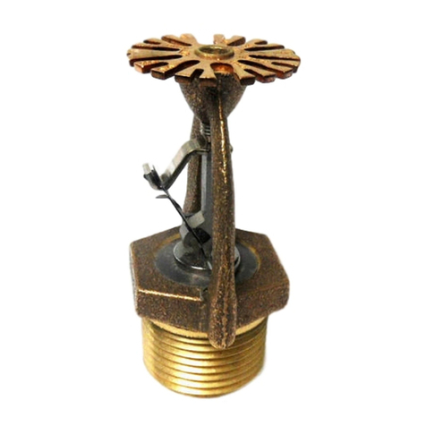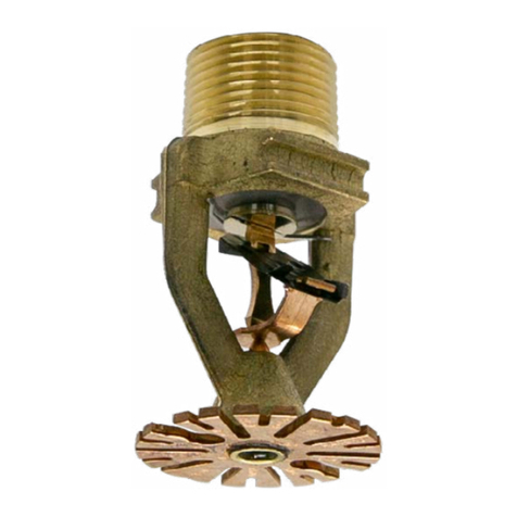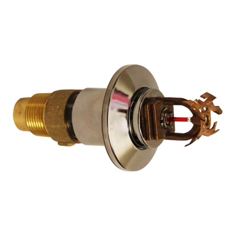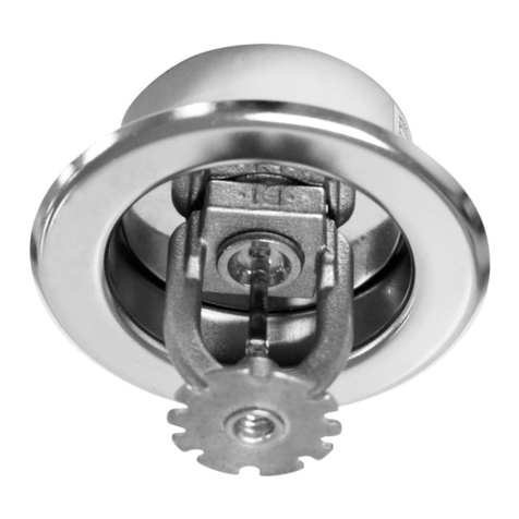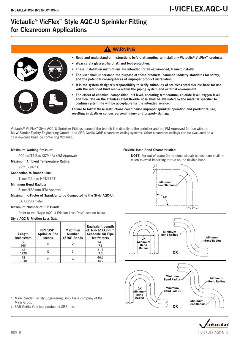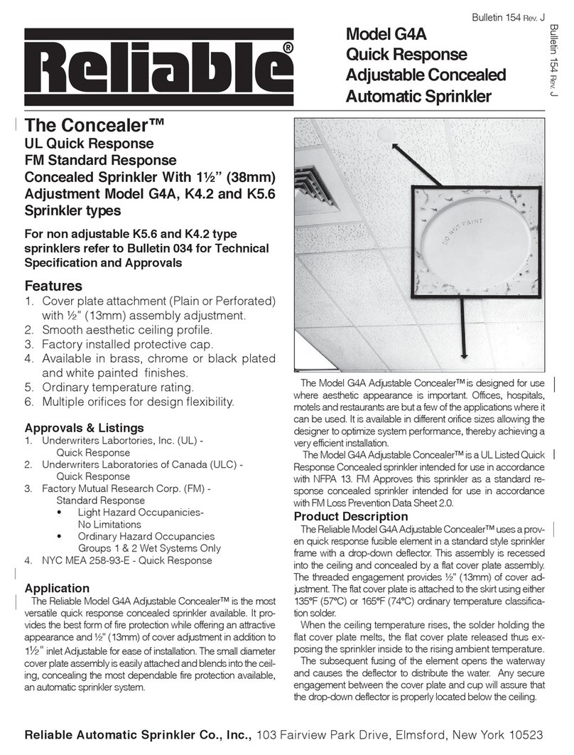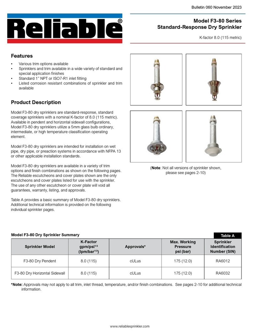
Installation Aid
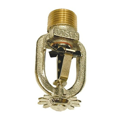
A protective cap is included for use during installation.
Important: The F1FR56 Sprinkler with Model CCP cover
plate is not an FM Approved combination.
Installation
Quick response sprinklers are intended for installation as
specified in NFPA 13. Quick response sprinklers and stan-
dard response sprinklers should not be intermixed.
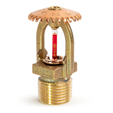
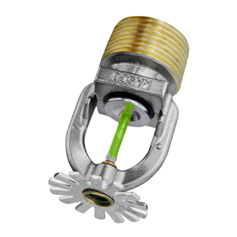
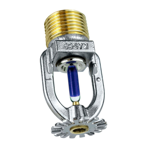
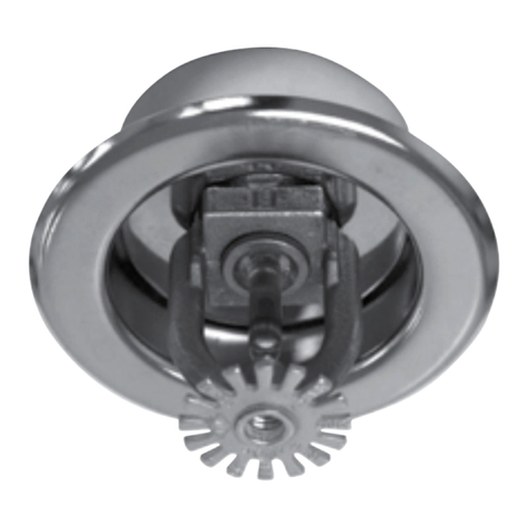
The Model F1FR56, F1FR56LL, F1FR42, F1FR42LL,
F1FRXLH & F1FR28 Recessed Quick Response Sprin-
klers are to be installed as shown. The Model F1 or F2 Es-
cutcheons illustrated are the only recessed escutcheons
to be used with the Model F1FR56, F1FR56LL, F1FR42,
F1FR42LL, F1FRXLH & F1FR28 Sprinklers. The use of any
other recessed escutcheon will void all approvals and ne-
gate all warranties.
When installing Model F1FR56, F1FR56LL, F1FR42,
F1FR42LL, F1FRXLH & F1FR28 Sprinklers, use the Model
D Sprinkler Wrench. Use the Model GFR2 Wrench for install-
ing F1FR56, F1FR56LL, F1FR42, F1FR42LL, F1FRXLH &
F1FR28 Recessed Pendent Sprinklers. Any other type of
wrench may damage these sprinklers.
NOTE: A leak tight ½” NPT (R1/2) sprinkler joint can be
obtained with a torque of 8-18 ft-lbs (10,8 - 24,4 N-m). Do
not tighten sprinklers over maximum recommended torque.
It may cause leakage or impairment of the sprinklers.
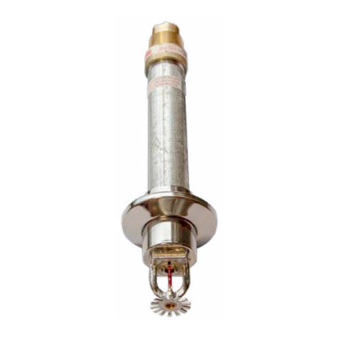
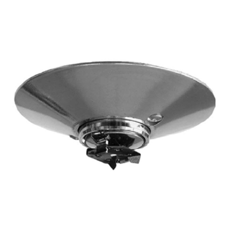
The Models F1FR56/CCP & F1FR56LL/CCP Concealed
Sprinkler use the ½” orifice, ½” NPT (R1/2), Model F1FR56
& F1FR56LL Pendent Sprinkler with a threaded Model CCP
cup which is factory attached to the sprinklers. The Model
F1FR56 Pndent is available in temperature rating of 135°F
(57°C), 155°F (68°C), 175°F (79°C) or 200°F (93°C). The
Model F1FR56LL Pendent is available only in a rating of
200°F (93°C). The concealed sprinkler assemblies are com-
pleted by the installation of the attractive low profile Model
CCP push on cover plate assembly, rated 135°F (57°C) or
165°F (74°C) for the F1FR56 and 165°F (74°C) for the FIFR56
LL. The cover plate and sprinkler cup assemblies are joined
using a cover plate skirt with flexible tabs for threaded en-
gagement. A choice of two cover plate assemblies provide
either 1/2” (13mm) or 5/8” (8mm) of cover adjustment,
Do not install these sprinklers in ceiling which have positive
pressure in the space above.
After a 25/8” (67mm) diameter hole is cut in the ceiling, the
sprinkler is easily installed with the Model RC1 Wrench. A
Teflon* based thread sealant should be applied to the sprin-
kler threads only. The Model RC1 Wrench is then used to
engage the sprinkler wrenching surfaces and to install
the sprinkler in the fitting. When inserting or removing the
wrench from the sprinkler/cup assembly, care should be tak-
en to prevent damage to the sprinkler. DO NOT WRENCH
ON ANY OTHER PART OF THE SPRINKLER. The cover
plate is then pushed onto the cup. Final adjustment is made
by hand turning the cover plate until the skirt flange makes
full contact with the ceiling. Cover plate removal requires
turning in the counter clockwise direction.
After installation, inspect all sprinklers to ensure that there
is a gap between the cover plate and ceiling and that the
four cup slots are open and free from any air flow impedi-
ment to the space above.
Concealed cover plate/cup assemblies are listed only for
use with specific sprinklers. The use of any other concealed
cover plate/cup assembly with the Model F1FR56 Pendent
Sprinkler or the use of the Model CCP Concealed cover
plate assembly on any sprinkler with which it is not specifi-
cally listed my prevent good fire protection and will void all
guarantees, warranties, listings and approvals.
Glass bulb sprinklers have orange bulb protectors to
minimize bulb damage during shipping, handling and in-
stallation. REMOVE THIS PROTECTION AT THE TIME THE
SPRINKLER SYSTEM IS PLACED IN SERVICE FOR FIRE
PROTECTION. Removal of the protectors before this time
may leave the bulb vulnerable to damage. RASCO wrench-
es are designed to install sprinklers when covers are in
place. REMOVE PROTECTORS BY UNDOING THE CLASP
BY HAND. DO NOT USE TOOLS TO REMOVE THE PRO-
TECTORS.
6.
*DuPont Registered Trade Mark
Figure 1 Figure 2

