MRC INE-SGW-1 User manual

Operating Instructions for
INE-SGW-1
Automatic Polarimeter
PLEASE READ THIS MANUAL CAREFULLY BEFORE OPERATION
3, Hagavish st. Israel 58817 Tel: 972 3 5595252, Fax: 972 3 5594529
MRC. 10.19

1
Table of Contents
I. APPLICATIONS AND FEATURES............................................................2
II. MAIN TECHNICAL PARAMETERS .........................................................2
III. STRUCTURE AND BASIC PRINCIPLES ................................................. 3
3.1 BASIC PRINCIPLES OF APPLICATION ................................................................ 3
3.2 OPTICAL ZERO PRINCIPLE............................................................................ 4
3.3 INSTRUMENT STRUCTURE ........................................................................... 6
IV. OPERATION INSTRUCTIONS ................................................................ 8
4.1 WORKING CONDITIONS .............................................................................. 8
4.2 SETTINGS AND KEYS................................................................................... 8
4.3 COMMUNICATION WITH PC AND SOFTWARE APPLICATION .............................. 17
V. MAINTENANCE AND CHECK.............................................................. 19
5.1 INSTRUMENT MAINTENANCE..................................................................... 19
5.2 CHECK THE OPTICAL PATH ......................................................................... 19
VI. MALFUNCTION AND TROUBLESHOOTING ...................................... 20

2
I. Applications and Features
The polarimeter is a kind of instrument for measuring the optical rotation of a substance. Through
measuring the optical rotation, the polarimeter can be used to analyze the concentration, content,
and purity of a substance. It can widely be used in various fields, including sugar making,
pharmaceuticals, petroleum, food, chemical and other industrial sectors and related institutions.
The model automatic polarimeter (hereinafter referred to as the instrument) uses light emitting
diodes as the light source, avoiding the trouble of frequent replacing sodium lights. The
large-screen LCD display on the instrument, simple and intuitive, stable and reliable.
II. Main Technical Parameters
Measuring modes: optical rotation, specific rotation, concentration and Sugar degree.
Light Source: LED
Wavelength: 589.3nm
Measuring range: ± 45 ° (Optical Rotation)
Minimum reading: 0.001 ° (Optical Rotation)
Accuracy: ±0.01(-15≤optical rotation ≤+15)
±0.02(optical rotation<-15or optical rotation>+15)
Repeatability: ≤0.002(optical rotation)
Display: large screen dot matrix LCD touch screen display
Test Tube: 200mm, 100mm ordinary type
Output Communication Interface: USB interface and RS232
Power Supply: 220V ± 22V, 50Hz ± 1Hz, 250W
Dimensions: 718mm × 342mm × 230mm
Net Weight: 35kg

3
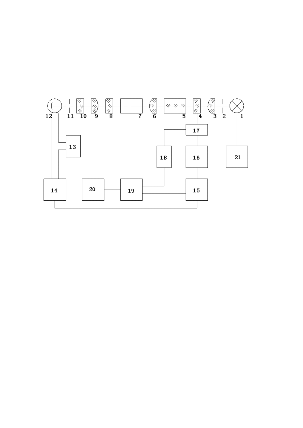
III. Structure and Basic Principles
3.1 Basic principles of application
As we all know, the visible light is a kind of electromagnetic wave with a wavelength of
380nm~780nm. In the statistical law, the corresponding light vibrations happens in possible
directions in the direction perpendicular to the light propagation direction, and the corresponding
amplitude of light vector (light intensity) in all possible directions are the same, usually called the
natural light. With certain devices (e.g., a polarizer), the vibration direction can be fixed in a
direction perpendicular to the light propagation direction, to form a so-called plane-polarized light.
When plane polarized light goes through a substance, the vibration direction of polarized light will
turn an angle, the substance is called optical material, and the angle that polarized light turned is
called optical rotation. If the plane polarized light goes through the optically puresubstance, and
the optical rotation is determined by the following three factors:
(a) The wavelength (λ) of the plane polarized light: for different wavelengths,the optical rotation
is different.
(b) The temperature (t) of the optically active substance: for different temperatures, the optical
rotation is different.
(c) The kind of an optically active substance: for different optically active substances, the optical
rotation is different.
The specific rotation [α]tλrepresents the rotation capacity of a substance.
Typically, the predetermined length of the optical tube is 1dm (100mm), the concentration of the
test substance solution is 1g/mL, and the temperature t℃. When the plane polarized light is at the
wavelength λ, the measured optical rotation is called the specific rotation of the substance, [α]tλ.
The specific rotation is only determined by the structure of substance. Therefore, the specific
rotation is the substance-specific physical constant.
αtλ=[α]tλ·L·C (1)

4
Where, L is the length of test solution (optical tube), with mm as unit; C is the concentration of the
optically active substance in the test solution. The instrument typically shows the result in the
grams of optically active substance in per 100mL solution.
If the specific rotation [α]tλof test substance is known in advance, the optical rotation αtλis
measured at certain temperature and wavelength, the length of the test solution is L, the
concentration of optically active substances in solution (C) can be calculated with the formula (2)
C=αtλ/[α]tλ·L (2)
If the solution contains a non-optically active, other than the optically substance, with
concentration of prepared solution and formula (2), the concentration of the optically active
substance (C) can be obtained, and the content of an optically active substance or purity can be
calculated.
3.2 Optical Zero Principle
If the natural light goes through the polarizer and the sequence analyzer in order, use the
orthogonal point of the light direction of a polarizer and an analyzer as zero. According to the law of
Marius, the relationship between the angle which deviates from the quadrature position of the
analyzer (α) and the intensity of the incident light of the analyzer (I):
I=I0COS2α
As shown in Figure 1,

5
0-90¡ã
BD
α+α'
C
A
+90¡ã
tB'
t
D' C'
t
t
图1
α+α'
α'
ββ
ββ ββ
When the both ends of Faraday ring is connected to a frequency of f sinusoidal alternating voltage
(u = Usin2πft), according to the Faraday Magneto-optical Effect, the vibration plane which the
plane-polarized light goes through will add an additional angle of rotation: α1 = β• sin2πft. When
there is a Faraday ring between the polariser and the analyzer, the intensity signal of emission light
from analyzer is as below:
a) In the quadrature position, the curve B and B' in Figure 1 can be obtained. The light intensity
signal is the superposition of the light intensity of a constant frequency and a 2f alternating light
intensity.
b) When the quadrature position is deviated from the right, the curve C and C' in Figure 1 can be
obtained. The light intensity signal is the superposition of the light intensity of a constant frequency
and a 2f alternating light intensity, see curve C'.
c) When deviating from the quadrature position leftward, the curve D and D ' in Figure 1 can be
obtained. The light intensity signal is the superposition of the light intensity of a constant frequency
and a 2f alternating light intensity, see curve D'. However, the phase of the alternating light
intensity is just the opposite of alternating light intensity signals when deviating from the
quadrature position.
Therefore, identify whether the alternating light intensity of the f component in signal intensity is
Figure 1

6
zero. It can accurately determine whether the polariser and the analyzer are in an orthogonal
position, identify the phase of f component alternating light intensity, and determine whether the
analyzer deviates from the orthogonal to the left or right position.
3.3 Instrument Structure
Figure 2
1-LED 6 - collimator 11 - aperture 16 - servo motor 21 - Power of
light source2-receiving
aperture
7 - tube 12 - detector 17-mechanical
drive
3 - condenser 8 - analyzer 13 - Automatic
high pressure
18-yard drive
Count
4 - polariser 9 - lens 14 - preamplifier 19-SCM
5 - modulator 10 - filter 15 - Motor Control 20-LCD
Figure 2 is a block diagram of the instrument. The light emitted by the light-emitting diode passes
through the diaphragm, condenser lens, polarizer, a Faraday modulator and collimator in order, and
forms a beam of light which is vibration plane collimated and plane polarized, changing with voltage
alternating of the Faraday ring. The light goes through the tube with test solution, enters the
analyzer, and then passes through the receiving objective lens, filter and diaphragm. The
monochromatic light with wavelength of 589.3nm goes into the photomultiplier tube, which
converts the light intensity signals into electrical signals, and the light is amplified by the
preamplifier. The automatic high-intensity light is incident on the photomultiplier tube in
accordance with an automatic pressure change photomultiplier tube, in order to meet the

7
requirement for measuring the colored sample with lower transmittance.
If the analyzer deviates from orthogonal position of the polarized plane where the light reaches, the
light goes through the alternating light intensity signal with frequency f, and through the
photomultiplier tube, it is converted into an electrical signal with frequency f. The signal which has
been pre-amplified and enters the motor control section, and then goes through the selected
frequency, the amplifier drives, the servo motor driven by a mechanical transmission polarizer, so
that the polarizer and the plane of polarized light generated by the analyzer reaches a quadrature
position, the electrical signal with frequency f disappears, and the servo motor stops.
As the instrument starts working, the polarizer follows the above process and automatically stops in
the orthogonal position, the counter is cleared at this time, defined as zero position. If the sample
tube with the rotation αis placed in the sample chamber, the incident plane polarized light deviates
from the quadrature position of the analyzer by the angle α.In accordance with the above
procedure, the polarizer again obtains a new quadrature position after turning the polarization by
angle α. Encoder counter and microcontroller circuit will turn the polarizer angle α,converting
optical rotation and display the measurement results on the LCD monitor.

8
IV. Operation Instructions
4.1 Working Conditions
1The instrument should be installed on a stable work station, free of vibration. The instrument
shall be 10cm away from the wall in all directions, in order to ensure effective heat dissipation.
2The instrument should be kept in dry environment, free from moisture and corrosive gas.
Make sure to operate the instrument under the environment of 20℃.
3The instrument uses 220V/50Hz AC power supply (AC electronic voltage regulator shall be used
if the power supply is instable). Get the power plug into an outlet and ensure safe grounding.
4.2 Settings and Keys
Turn on the power, and the initial page is shown as below:
Figure 3
Press any key to enter the operation interface, see Figure 4:

9
Figure 4
1.operation interface:
(1) press ‘ReMeas’ to test the sample. See Figure 5:
Figure 5
(2) press ‘stop’ to stop test the sample, see Figure 6

10
Figure 6
(3) press ‘Zero’, data zero and stop to retest the sample, see Figure 7
Figure 7
If the measurement is finished yet, "send" will instead of "wait" key show on display, how to use
"send" see 4.3 .
2. Measuring modes:
4 modes: optical rotation, specific rotation, concentration and Sugar degree.
(1) Optical rotation, see Figure 8

11
Figure 8
(2) specific rotation, press ‘
’, see Figure 9 (Need input “Length of test tube (dm), Concentration,
ReMeas Tims”)
Figure 9
(3) concentration, press ‘
’ into concentration mode, see Figure 10 (Need input “Length of test
tube (dm), C, n” If
is negative, you need not input “-”, it can display “-” automatically, “-”
means left-rotation sample)

12
Figure 10
(4) sugar degree, Press "C", it shows as in Figure 11:
Figure 11
Press ‘Z’ back to optical rotation mode. See Figure 12.

13
Figure 12
Notice:after measurement finished, press ‘AV
’will show the data of specific rotation; when
specific rotation mode, press ‘
AV
’will show the data of optical rotation; when concentration
mode, press ‘CAV’will show the data of optical rotation. Press these keys again, back to the
mode before.
3. Modify the Test parameter
(1) Press ‘C’, see Figure 13
Figure 13

14
(2) press ‘tubelength’to change the length, see Figure 14
Figure 14
(4) press ‘Meastimes’to change the test time, see Figure 15
Figure 15
Notice: Select the measurement time between 1 and 6. Select 6 if it is necessary to
automatically calculate the mean square deviation. So only when the measurement time = 6.
Display the square deviation.

15
4. communication port
USB and RS232, The default is RS232, Press ‘RS232’to change to ‘USB’, see Figure 16
Press ‘USB’to change to ‘RS232’
Figure 16
5. Para set
(1) Press ‘Para Set’, see Figure 17
Figure 17
(2) press ‘Time’, see Figure 18

16
Figure 18
Press ‘Meas’back to test mode.
6. the notice of the sample
a. Put the test tube containing distilled water or other blank solvent into the sample chamber,
and close the cover. Press the “clear”button, display “0”. (If there are air bubbles in the
test tube, the first thing should be done is to make the air bubbles float on the protruded
tube-neck. The atomized water drops on the both ends of test tube should be wiped dry.
The screw-nut of the test tube should not be screwed down too tightly, so as to avoid
stress, otherwise, the readings may be affected. When placing the test tube, care should
be taken for the marked position and direction.)
b. Take out the test tube, then, inject the sample to be measured into the test tube.
According to the same position and direction, put the test tube into the sample chamber,
then, close the cover. Now the instrument will indicate the optical rotation of the sample.
c. The instrument will do repetition measurement for n times automatically, and display the
value (when n=6, 1n
Sis effective). If n=1, press “repetition-measurement”button to
reset. If n>1, press “repetition-measurement”button, the instrument will measure
repeatedly for n times.
d. Please press “zero”button before measurement every time.

17
4.3 Communication with PC and Software Application
1. The methods of building communication with PC:
Hereinafter, "PC" refers to the computer installed windows XP operating system; "the instrument"
refers to INE-SGW-1 model polarimeter.
Precautions when connecting hardware:
(1) Before the power of PC and the instrument is turned on, make sure the USB or RS232
communication cable well connect both devices;
(2) Too chose RS232 or USB on the instrument. The default port is RS232
(3) The appropriate hardware drivers must be installed on PC. First, provide the path of the factory
CD. Open the "Driver" folder and run VCPDriver_V1.1_Setup.exe. After connecting the USB
communication cable and turn on both devices, the PC displays "Found new hardware". Follow
the guidance of new hardware installation wizard, and automatically complete the installation.
If it can not automatically complete the installation, select manual installation, that is, under
the given path, find the driver.Point the path to the CD-ROM provided by the factory. Locate
"Driver" folder, and select ‘stmcdc.inf’. Follow the computer prompts, click "Next "until the
hardware driver installation is completed.
2. Operation of the communications software:
(1) To display, save and print the test results In PC, you need to install communications software
applications. Installation method: Double-click the setup icon which is in the "SETUP" folder on
the user CD.
(2) Double-click on the application icon which appeared after installing the software. Start the
communications application software.
(3) After turn on the instrument, choose RS232 or USB first.
(4) Before transferring test data each time, you may add some related information in the empty
file at lower part of the window.
(5) After a round of testing on the instrument, press the "send" key to upload the test results. The
PC can generate one-page sheet with page number! The application software can generate
1,000 sheets in total.
(6) keys and menu commands:

18
a) After the communication port is selected, the "Accept" key will be grayed out. Only when
the key is grayed out, the PC communication port is activated and under waiting state. So
when performing certain menu commands and the key is enabled, make sure to click the
key again to make it grayed out and under waiting state, if you need to upload data.
b) Make sure that the instrument is connected with the printer, which is turned on and work
normally. Then click "Print" key. Otherwise it will lose all data which has been uploaded. If
the command is executed normally, all displayed data can be printed out in the exactly
same format and content. If you need to print other page of sheet, please click on the
pull-down key to call out the required sheet, and then print. In "Parameter Settings",
under the drop-down sub-menu, click "Printer Setup", you can have two windows, to fill
the horizontal and vertical printing. You only need to reduce or increase (less than 1 or
greater than 1) the scale factor.
c) Click on "save and exit", you can save the currently displayed page sheet in the same
layout as an individual picture. After save, the system will exit. NOTE: Other pages sheets
will be discarded.
d) Click the "Open" key, only the *. dat data file which has been saved by the software be
opened. Note: when this command is executed, all data sheets which have been
uploaded will be immediately over written by the opened data file.
e) "Exit without Save": without any further operation, exit the software.
f) Other drop-down menu commands and restrictions:
"Save Data": save all uploaded data to the dat file under the name you gave and clear all existing
data sheet.
"Open File", "Save and Exit", "Print Results" and "Exit": the functions of the four commands are
exactly the same as the corresponding key in the window function. See above for relevant
description.
"Add Data": add all existing sheet data to the * dat file which you specify and behind the data.
"Export to Excel and Exit": Export all uploaded data sheet content to the Excel spreadsheet under
the name you gave and then exit.
Notes:
(1) Specific rotation calculation formula: [α] = 100α/LC

19
Where, αis the measured optical rotation (degree)
C is the weight of test substance in every 100ml of solution (gram)
L is the length of the solution (decimeter)
To measure the specific rotation, use mode 2.
(2) With measured specific rotation, the purity of the sample can be calculated:
Purity = measured specific rotation / theoretical specific rotation
(3) Measure the international sugar degree:
In accordance with the international sugar degree standards, it prescribes to use 26g pure
sugar with 100ml to make solution. Use 2dm tubes, and conduct measurement through
sodium light under 20 ℃. The optical rotation is +34.626 °, the sugar degree is 100 ° Z. With
Mode 4, you can directly read the international sugar degree from the instrument.
V. Maintenance and Check
5.1 Instrument Maintenance
The instrument should be placed in a dry place, away from corrosive gases, and free of severe vibration.
After using for a period of time, due to the influence of the external environment, the surface of the
optical system may gather dust or mildew, which will affect the performance. It can be cleaned gently
with a small cotton stick dipped with the butyl acetate or ethanol.
If there is some moldy, after it has been wiped with cotton dipped in alcohol, then with a small amount
of cerium oxide (Pink) or calcium carbonate, wipe it again gently. Don't disassemble the optical parts.
Once the optical component is disassembled, it will destroy the original light path, which must be
re-adjusted. Otherwise the instrument performance will be affected or couldn't work anymore. If any
optical component must be removed for replacement, it should be sent to our factory to handle.
5.2 Check the Optical Path
Place a wafer with outer diameter of φ30mm at the outlet of test beam in the sample tank. In the dark
room, you can see the spot which was projected from the test beam on the wafer. The spot should be
Table of contents
Other MRC Laboratory Equipment manuals
Popular Laboratory Equipment manuals by other brands

Roper Scientific
Roper Scientific Photometrics SenSys manual

REITEL
REITEL BIOSTEAM CENTER operating instructions

Maestrogen
Maestrogen Ultra Slim LED Illuminator instruction manual

Medela
Medela Calesca Quick start card

Pacific Image Electronics
Pacific Image Electronics Glite 965BW user manual

biosystems
biosystems X-CLARITY user manual

Grant-bio
Grant-bio LMC-3000 USA operating instructions

Porter
Porter Reliant user manual

Keysight Technologies
Keysight Technologies N778-C Series user guide

Brunswick
Brunswick Innova 4000 manual

CAMAG
CAMAG DBS-MS 500 instruction manual

Thermo Scientific
Thermo Scientific HAAKE Viscotester iQ instruction manual