INDEX
Warning: Safety Precautions ............................................................ 1-9
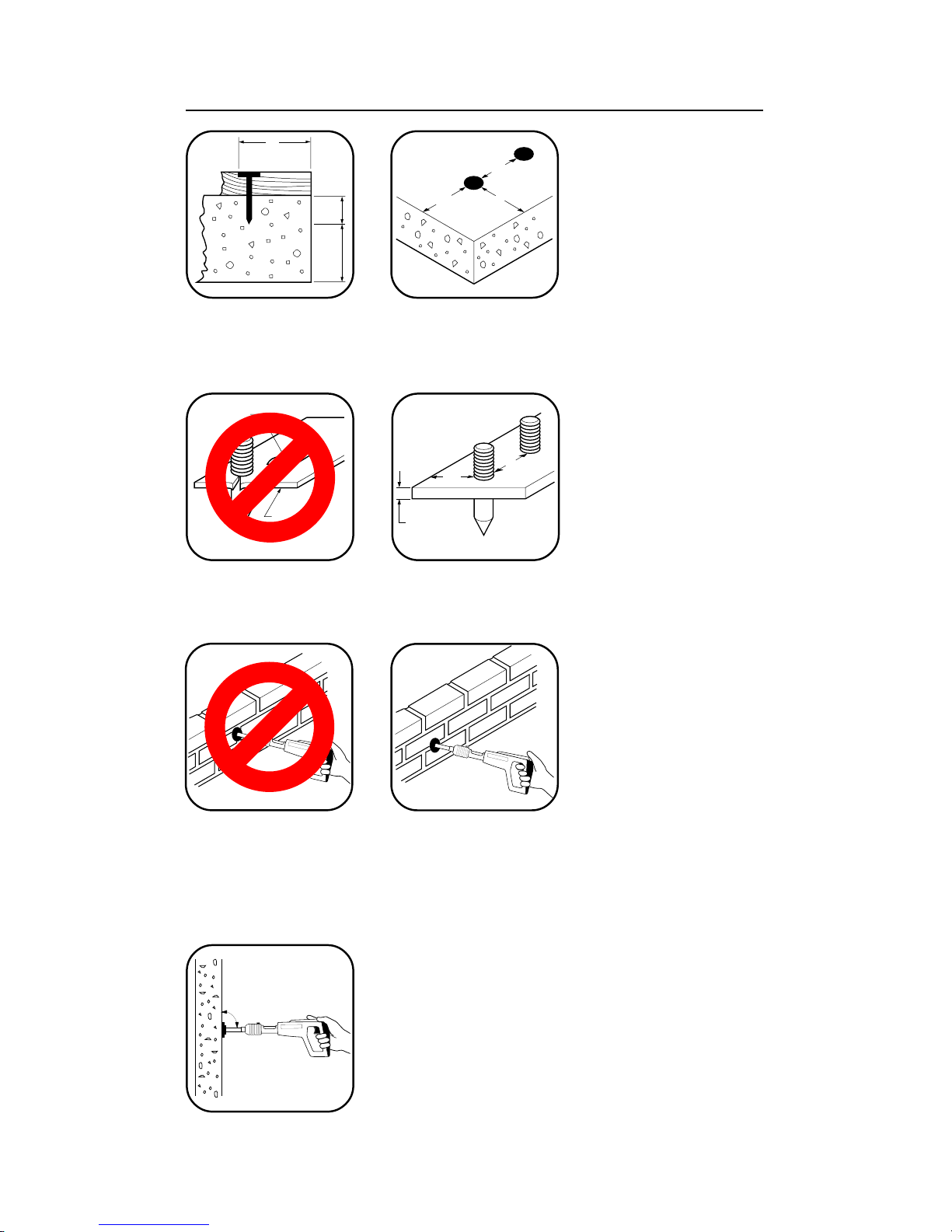
Why A Fastener Holds ....................................................................... 10
Selecting Fasteners and Powder Loads ............................................ 11
Operation ...................................................................................... 12,13
Parts List ............................................................................................ 14
Accessories........................................................................................ 14
Barrel Replacement ........................................................................... 15
Tool Disassembly and Assembly .................................................. 16,17
Troubleshooting ............................................................................ 18,19
Fasteners ........................................................................................... 19
Application Chart........................................................................... 20,21
Parts and Accessories ....................................................................... 21
Warranty...............................................................................Back Cover
REMINGTON
Powerdriver Models 489 and 490
TheRemingtonPowerdriverModels489and490aredesignedforuse
withRemingtonpowder22caliberTypeAcrimpedloadsandReming-
ton Power Fasteners which are no longer than 2 1/2". Remington
Power Fasteners are manufactured from special steel and heat
treated to produce a very hard yet ductile fastener.
REMINGTON
490-02
Powder Load*
Maximum 2 1/2"
Trigger
Barrel Assembly
* Not provided with tool.
Spall Shield*
Power Fastener*
Muzzle
Recommended
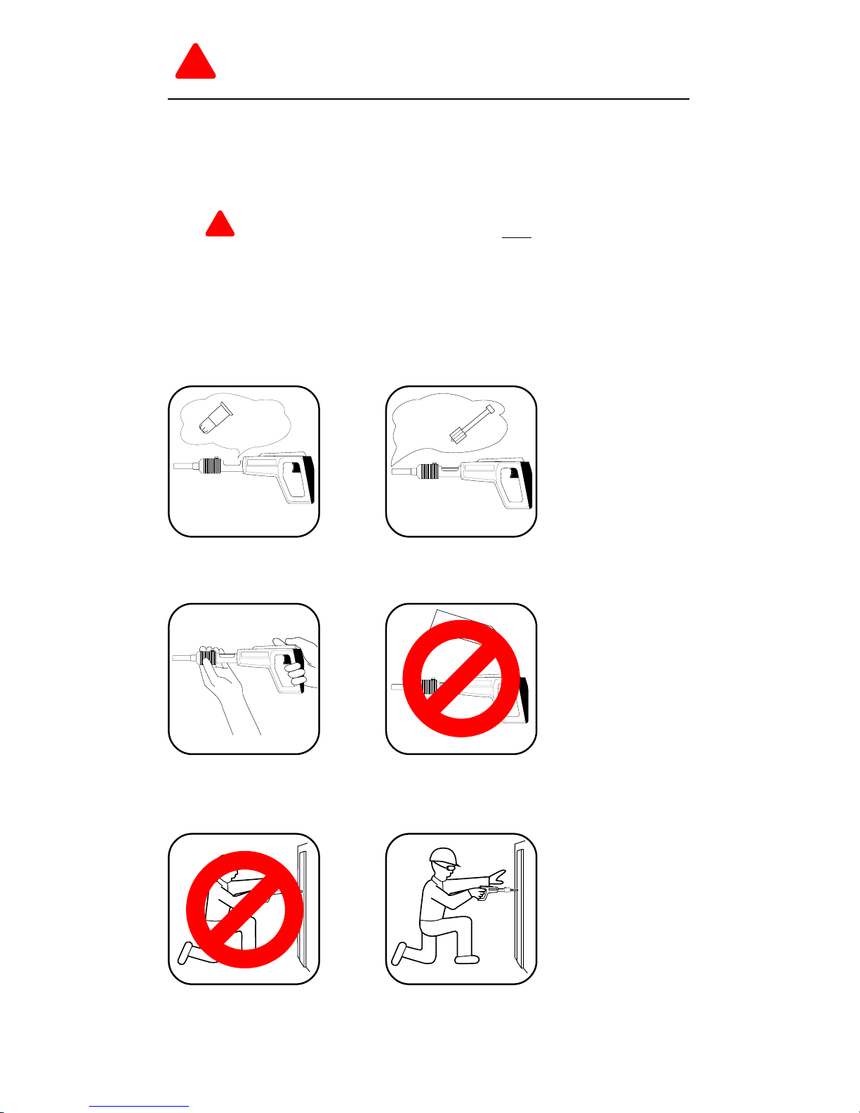
Approved Eye
Protection*