2
106088
INDEX
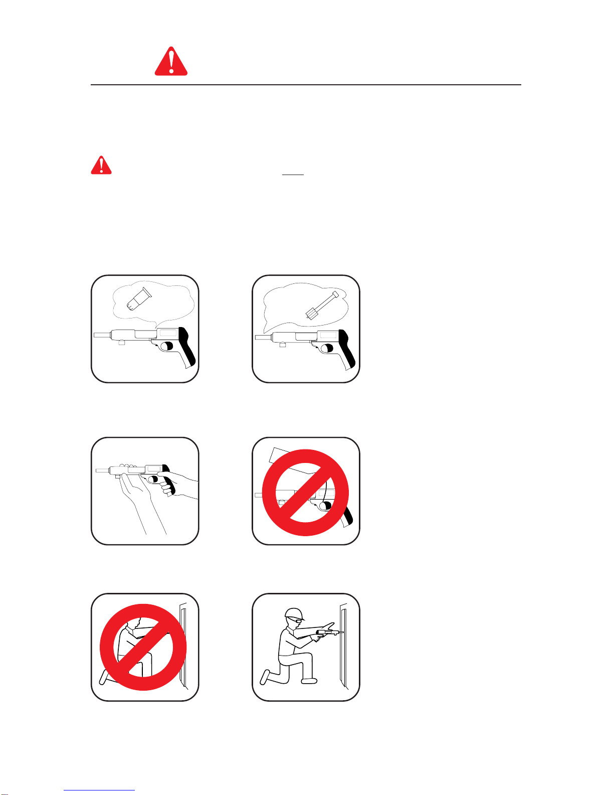
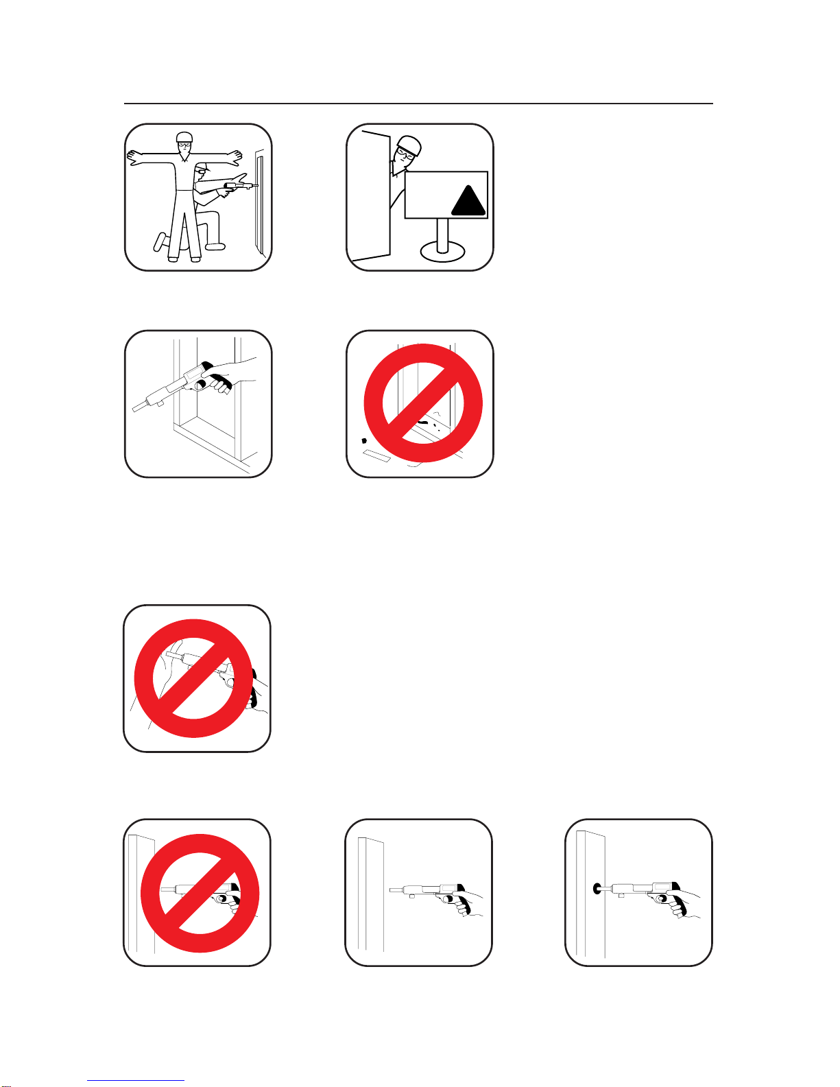
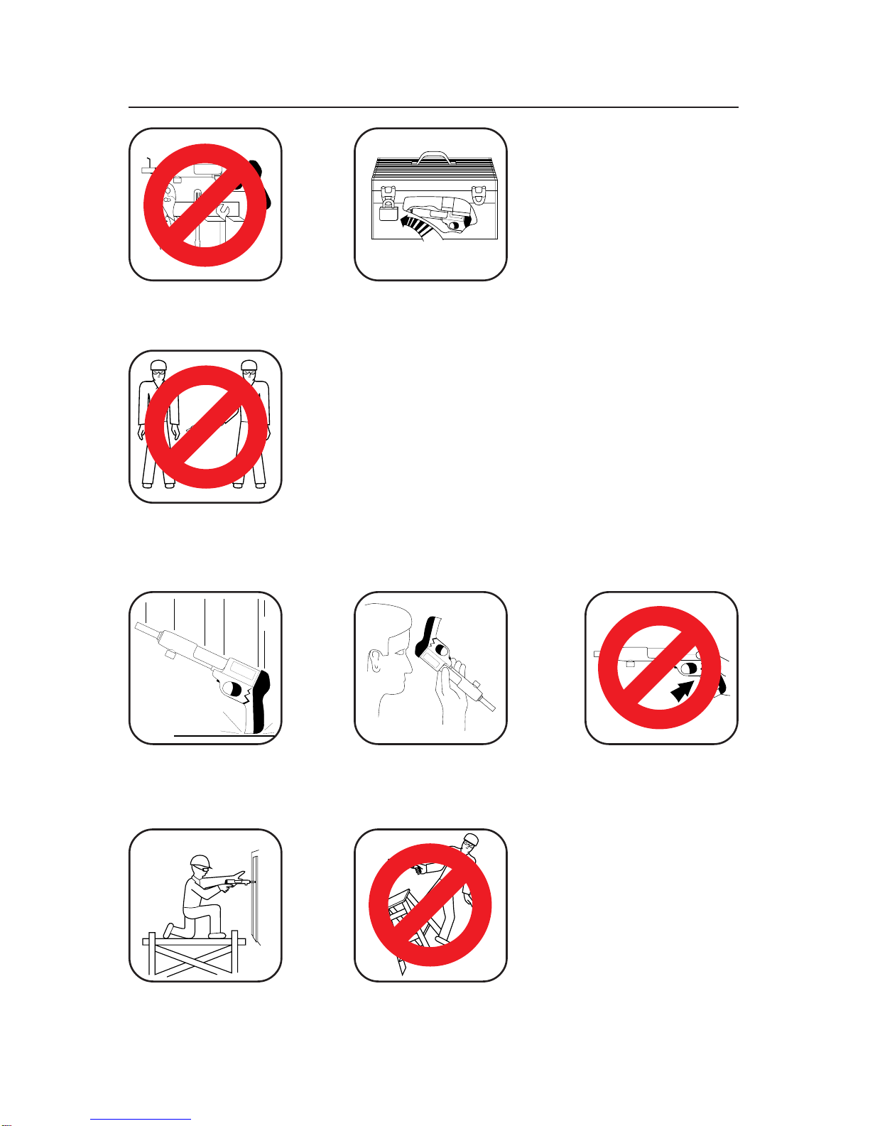
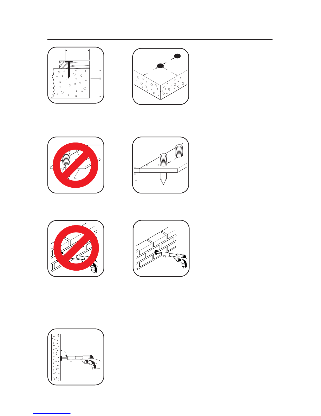
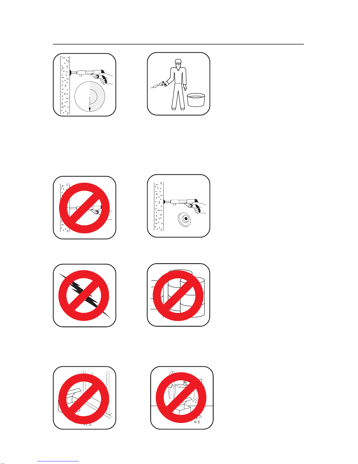
Warning: Safety Precautions............................................................................. 2-11
Why a Fastener Holds.......................................................................................... 12
Selecting Fasteners and Power Loads ................................................................ 13
Operation ....................................................................................................... 14, 15
Maintenance......................................................................................................... 16
Troubleshooting ............................................................................................. 16, 17
Parts Central ........................................................................................................ 17
Parts List .............................................................................................................. 18
Accessories.......................................................................................................... 19
Tool Disassembly and Assembly ................................................................... 19, 20
Buffer and Piston Replacement ........................................................................... 21
Application Chart............................................................................................ 22, 23
Warranty.................................................................................................Back Cover
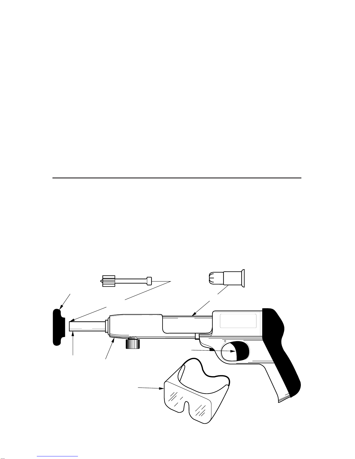
* Not provided with tool.
REMINGTON
Power Fastener*
Barrel
Assembly
Trigger
Maximum 2 1/2" - Model 482
Power Load*
Muzzle
Spall Shield
Recommended
Approved Goggles
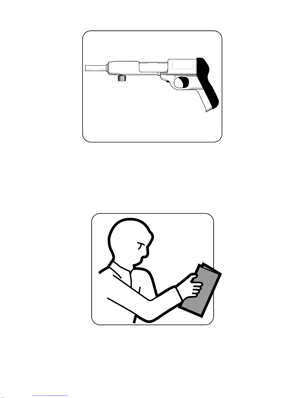
REMINGTON
Model 482 Powder Actuated Fastening Tools
The Remington Model 482 Powder Actuated Fastening Tool is designed for use
with Remington 22 caliber Type A crimped loads and Remington Power Fasten-
ers. Remington Power Fasteners are manufactured from special steel and heat
treated to produce a very hard yet ductile fastener.