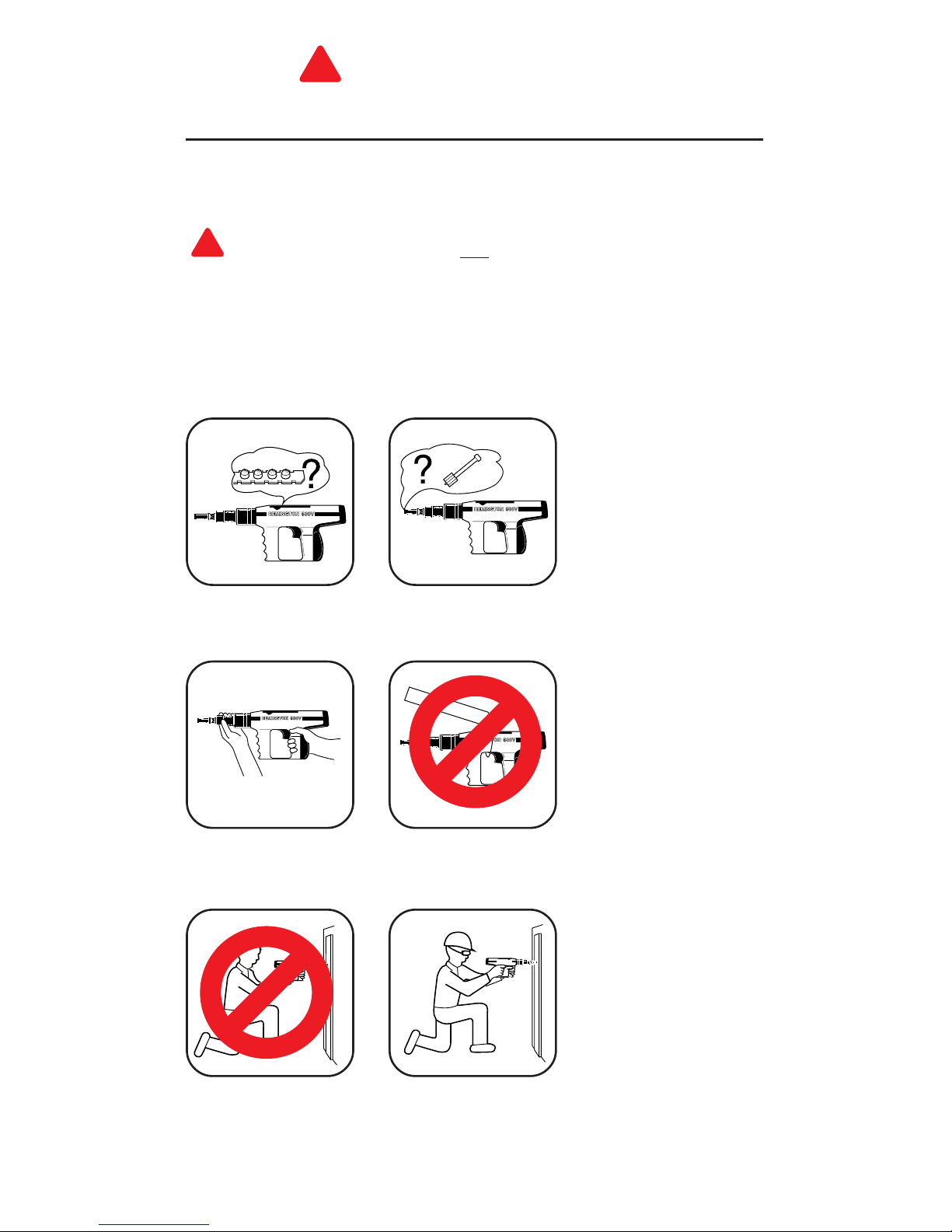
Remington Power Pro 500V User manual

IMPORTANT:
Read all instructions and warnings found in this manual and on power load
packaging before operating your powder actuated tool. This manual should
always accompany the tool and be transferred with it upon change of
ownership.
Operating
Instructions
482-1
POWDER ACTUATED TOOL
MANUFACTURERS´ INSTITUTE INC.
™
G 029
®
®
Power Pro™
Semi-automatic
Model 500V

2
114918
Power Fastener*
Recommended
Approved
Eye Protection
Muzzle/
Guide
Barrel
Assembly
Trigger
Spall
Shield
10-Shot
Power Load
Strip*
*Not provided with tool
Power
Indicator
Adjustment
Wheel
Index
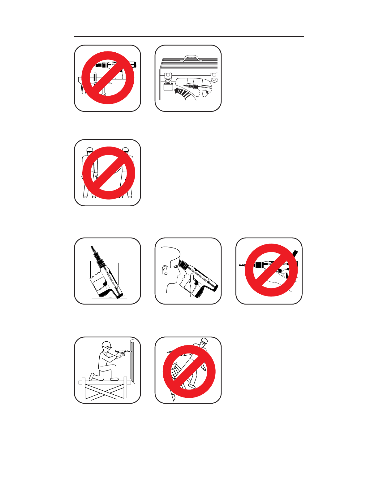
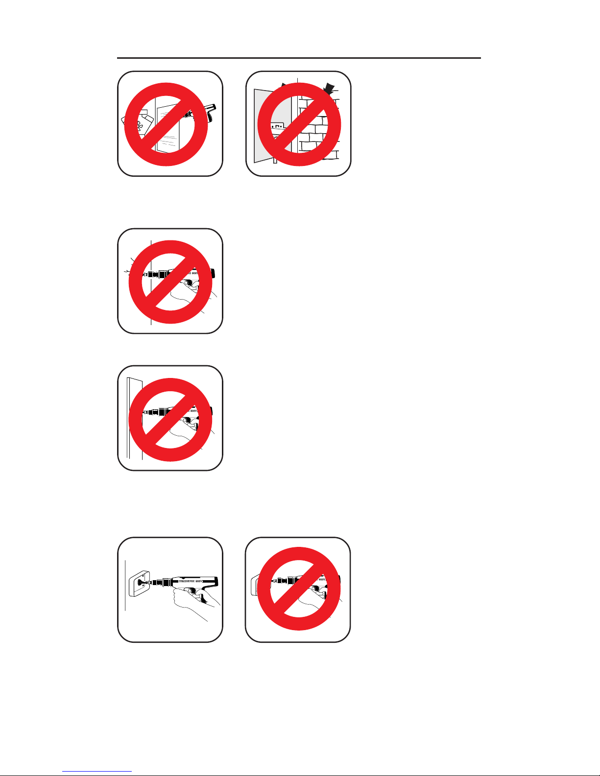
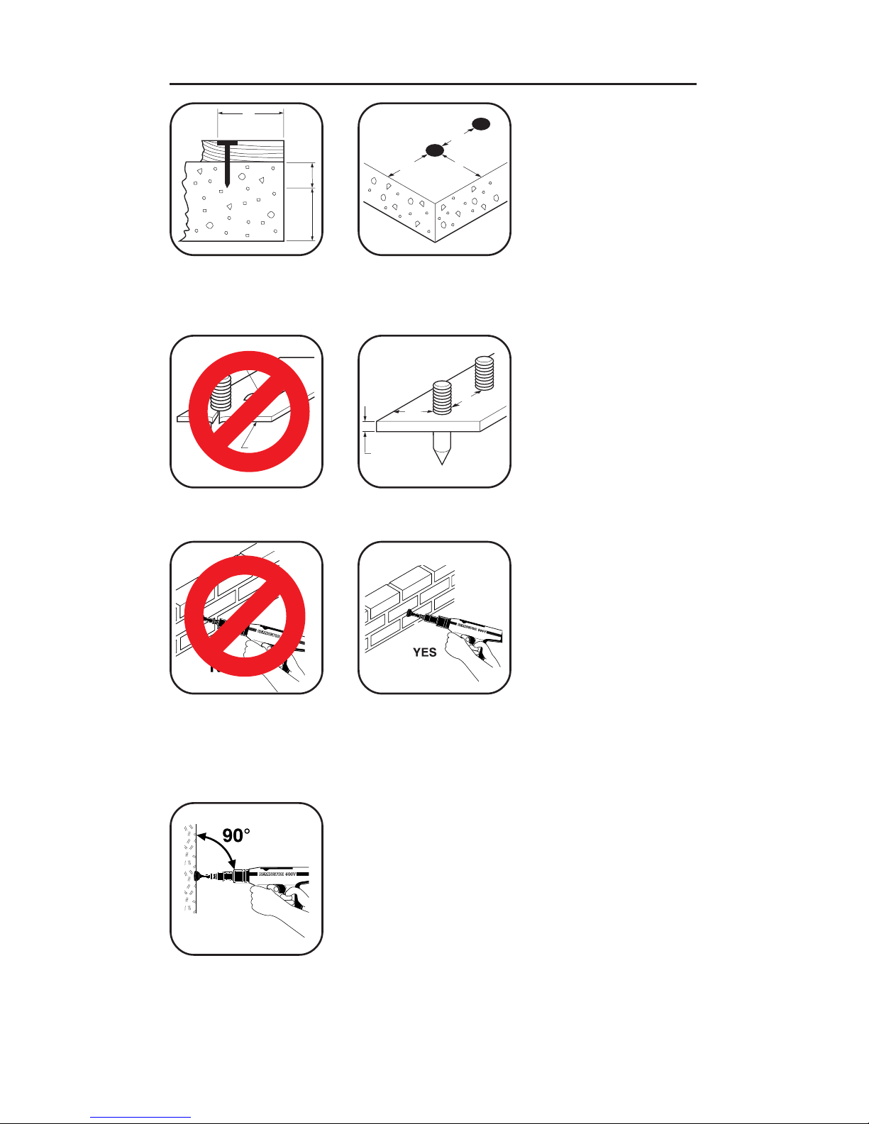
Warning: Safety Precautions .......................................................................... 3-11
Why A Power Fastener Holds ............................................................................ 12
Selecting Power Fasteners and Power Loads ................................................... 13
Operation ...................................................................................................... 14-16
Maintenance ...................................................................................................... 16
Parts List ...................................................................................................... 16, 17
Accessories ........................................................................................................ 17
Tool Disassembly and Assembly .................................................................. 18-25
Troubleshooting Guide ................................................................................. 26, 27
Application Chart .......................................................................................... 27, 28
Replacement Parts and Accessories ................................................................. 29
Technical Service ............................................................................................... 29
Repair Service ................................................................................................... 29
Parts Centrals .................................................................................................... 30
Limited Warranty ................................................................................................ 31
REMINGTON®
Power Pro™ Semi-automatic Model 500V
The Remington®Power Pro™ Model 500V is designed for use with Remington®.27
caliber power load strips and Remington®power fasteners. Remington®power
fasteners are manufactured from special steel and heat treated to produce a very
hard, yet ductile, fastener.

3
114918
1. ALWAYS handle the tool as if it were loaded. Before starting work, check that
the tool is unloaded and the muzzle is clear. NEVER load a tool unless it is going
to be used.
BEFORE USING
!
WARNING ICON G 001
Warning: Safety
Precautions
The following pages contain detailed warnings, cautions, and rules of safe operation.
Read carefully and become familiar before operating to avoid serious injury. We
expressly disclaim any liability for any injury to persons or damage to property which
result from your failure to take the precautions contained in this manual.
!
WARNING ICON G 001
WARNING: This tool is designed only for use by qualified operators. Qualifica-
tion is obtained through a thorough understanding of the
Safety Precautions
and
operating instructions as defined in this operating manual. NOTE: The labor regula-
tions of many states require that the operator of this tool on a job site be thoroughly
trained and certified for competence prior to operating this tool. For certification
procedures, call: DESA Specialty Products™ Technical Services Department, 1-800-
858-8501 (USA) or 1-905-826-8010 (Canada) or visit www.desatech.com.
2. ALWAYS inspect to make sure the tool is working properly. If the tool does not
work properly, remove from service and tag DEFECTIVE. DO NOT use the tool
again until it has been properly repaired.
3. Operators and bystanders must ALWAYS wear goggles and ear protection
which meet or exceed the accepted standards for adequate protection in your
country. In the USA, refer to ANSI standards. In Canada, refer to CSA standards.
DEFECTIVE
G 018
G 018

4
114918
Safety Precautions
4. ALWAYS clear the work area on all sides and post appropriate warning signs on
job sites.
1. NEVER place your hand over the muzzle. Accidental discharge can cause
serious injury.
HANDLING THE TOOL
2. NEVER place your finger on the trigger until the tool’s muzzle is against the work
surface.
5. ALWAYS make sure the work area is clean from loose material and debris.
POWDER
ACTUATED
TOOLS
IN USE
WARNING
!
G 018
G 018
G 018

5
114918
Safety Precautions
4. NEVER carry or pass a loaded powder actuated tool. NEVER point a powder
actuated tool at anyone.
3. ALWAYSstoreUNLOADEDpowder actuated tool and power load strips in a locked
container. Keep power loads of different power levels in separate containers.
5. If the tool is dropped, inspect for damage and repair it before continuing to work.
NEVER use a damaged tool.
6. ALWAYS take precaution to maintain your balance while operating a powder
actuated tool.
G 018
POWER
LOADS
POW
LOAD
G 018
G 018
G 018

6
114918
Safety Precautions
7. An operator taking medication should take extra precautions while handling the
tool. NEVER drink alcoholic beverages or take medications which impair your
vision, balance, or judgement before using a powder actuated tool.
KNOW YOUR FASTENING BASE MATERIAL
1. ALWAYS know the thickness and type of base material into which you are
fastening. NEVER GUESS. Test the base material by using the Center Punch
Test. The Center Punch Test is performed by using a hammer to test drive the
particular power fastener to be used into the material. If the point penetrates easily,
the material is too soft. If the point becomes blunt, the material is too hard. If the
materialfractures,cracks,orshatters,thematerialistoobrittle.Testfasteningscan
be made if the material shows a clear fastener impression and the fastener point
is not blunted. ALWAYS use test fastenings to determine the correct power load
level and the tool’s power indicator setting (see
Power Loads and Power Indicator
Setting,
page 13). Operators and bystanders must ALWAYS wear eye and ear
protection which meet or exceed the accepted standards for adequate protection
in your country. In the USA, refer to ANSI standards. In Canada, refer to CSA
standards.
TOO HARD
Point
flattens
482-29
G 018
?
?
?
?
482-26
CENTER
PUNCH TEST
482-27
TOO BRITTLE
Surface
shatters
482-30
G 018
Start
YELLOW
POWER
LEVEL 4
GREEN
POWER
LEVEL 3
RED
POWER
LEVEL 5
TOO SOFT
Sinks in
with
average
hammer
blow
482-28
G 018
?
?
?
G 018

7
114918
Safety Precautions
3. NEVER make fastenings in spalled or cracked areas.
2. NEVER attempt to drive power fasteners into very hard or brittle materials
including, but not limited to, cast iron, glass, tile, stone, brick, or hardened steel.
Materials of this type tend to shatter and create hazard from flying particles.
4. NEVER drive power fasteners into thin or easily penetrated materials unless it
is backed by concrete or steel. When in doubt, such as when base material is
concealed, conduct a Center Punch Test (See page 6). Check continually to
avoid fastening into unsuitable material, especially in older buildings.
5. DO NOT fasten through or within 1/2" of predrilled or pre-punched holes.
CAST IRON GLASS
G 018
TILE BRICK
482-33
G 018
G 018
G 018
G 018

8
114918
Safety Precautions
7. DO NOT drive power fasteners into steel base material less then 3/16" thick,
within 2" of a weld, within 1/2" of the edge, or within 1" of another power fastener.
6. DO NOT drive power fasteners into concrete less than three times as thick as the
intended fastener penetration, within 3" of the edge, within 3" of another power
fastener, or within 3" of a failed power fastener.
8. When fastening into masonry walls, always drive into horizontal mortar joints,
NEVER into vertical mortar joints. BE CAREFUL, a poorly laid joint may permit
too much penetration and/or unsatisfactory holding power.
OPERATING THE TOOL
1. ALWAYS hold tool perpendicular to work surface.
3"
3X
1X
482-38
3" 3"
3"
482-39
TOO THIN
WELD
482-40
G 018
3/16" MIN
1/2"
1"
482-41
G 018

9
114918
Safety Precautions
2. Should the tool fail to fire, hold the muzzle firmly against the work surface for 30
seconds. Release the trigger and remove pressure on the tool while holding the
muzzle against the work surface. Again press the tool firmly against the work
surface and pull the trigger. If the tool still fails to fire, hold the tool firmly against
the work surface for another 30 seconds before advancing the power load strip.
Use remaining loads in strip. Discard power load strip into water or oil.
3. ALWAYS use the spall shield when driving directly into concrete or steel.
ALWAYS wear eye protection.
4. NEVER use a powder actuated tool in an explosive or flammable atmosphere or
when non-sparking tools are required.
POWER LOADS AND POWER FASTENERS
1. NEVER leave unfired power load strips on floors or work surfaces.
482-49
G 018
GASOLINE
GAS
OLINE
482-50
G 018
POWER
LOADS
G 018
POWER
LOADS
G 018
WATER
G 018
Spall
Shield

10
114918
Safety Precautions
2. Remington®power load strips are available in three power levels – green (level
3), yellow (level 4), and red (level 5). Green is lowest power level, red is highest
power level. ALWAYS use test fastenings to determine the correct power load
level and the tool’s power indicator setting (see
Power Loads and Power
Indicator Setting,
page 13).
IMPORTANT:
Purple (level 6) power load strips
will not function in model 500V tool.
3. NEVER use power loads in firearms.
5. A color blind person must take extra precautions to prevent the chance of mixing
the power load strips of various levels.
4. NEVER carry power fasteners or other hard objects in the same pocket or
container with power load strips.
1
2
3
4
56789
10
11
12
1
22
L
E
K
C
I
N
B
R
A
S
S
482-54
C
A
L
I
B
E
R
27 NOTE:
Failure to start with
the lowest power level
can result in overdrive
condition and will re-
sult in damage to tool
(See page 13).
G 018 G 018
POWDER
LOADS
ONLY
482-57
POWER
LOAD
STRIPS
ONLY
YELLOW?
GREEN?
RED?
G 018
Start
YELLOW
POWER
LEVEL 4
GREEN
POWER
LEVEL 3
RED
POWER
LEVEL 5

11
114918
Safety Precautions
6. Power fasteners are a permanently installed fixture. An act of demolition is
required for their removal. Appropriate safety precautions must be taken.
9. If work is interrupted for any reason, ALWAYS remove the power load strip
before removing the power fastener.
8. NEVER pry a power load out of the strip. Prying can discharge the load causing
serious injury (See
Troubleshooting Guide,
pages 26 and 27). NEVER attempt
to reload used strips.
7. NEVER use common nails or other materials as fasteners. Remington®Power
Fasteners are manufactured from special steel and heat treated to produce a
very hard, yet ductile, fastener.
482-59
G 018
Plastic Flute
Shank
Head
482-60
G 018

12
114918
Why A Power Fastener Holds
WHY A POWER FASTENER HOLDS IN CONCRETE
The compression bond of the concrete to the power
fastener accounts for the majority of the holding power.
The power fastener displaces the concrete which tries to
return to its original form causing a squeezing effect.
Maximum holding power is achieved when the depth of
penetration produces a bond on the power fastener equal
to the strength of the concrete. As a general rule, penetra-
tion should be approximately 1" to 1 1/4" into the base
concrete. Make sure the concrete is at least three times as
thick as the intended power fastener penetration. NEVER
have the power fastener point protrude through the concrete.
NOTE:Concrete needs to cure for 28 days before maximum fastening holding power
will be achieved.
WHY A POWER FASTENER HOLDS IN STEEL
Holding power in steel depends on the elasticity of the
steel. The steel pushes back on the shank of the power
fastener.
Drop a marble into water; the water parts, the marble
continues down, the water closes back. This is similar to
the reaction when a power fastener penetrates steel.
In steel, the point of the power fastener must penetrate
completely through for highest holding power. If the
power fastener does not penetrate, the spring action of
the steel pushes back on the point and tends to force the
power fastener out.
Recommended applications are between 3/16-3/8" steel.
NOTE: When fastening in steel be sure the point goes through the steel.

13
114918
Piston Extended
Out of Muzzle
Selecting Power Fasteners
and Power Loads
FASTENING INTO CONCRETE
The proper power fastener length can be determined by
adding the thickness of the material to be fastened and
the amount of power fastener that will actually penetrate
the concrete. The concrete must be three times as thick
as the intended power fastener penetration. In most
cases, penetration should be approximately 1" to 1 1/4"
into the base concrete material.
FASTENING INTO STEEL
The proper power fastener length can be determined by
adding the thickness of the material to be fastened and
the thickness of the steel. The point of the power
fastener must go completely through the steel.
POWER LOADS AND POWER
INDICATOR SETTING
Properfasteningrequiresthecorrectcombinationofpower
loadlevelandthetool’spowerindicatorsettingtomatchthe
fastener length for a given application. A general estimate
for the power load level needed for a given application can
be found in the application chart on page 27. For a given
power load level, always start with the lowest power
indicator setting on the tool. If the first test fastening does
not penetrate to the desired depth, increase the tool’s
power indicator setting until a proper fastening is made.
IMPORTANT: Damage to the tool will result if the above
instructions are not followed (see illustrations to right
and lower right).
OVERDRIVEN POWER FASTENERS
AND PISTON
An overdriven power fastener results when the combi-
nation of power load level and the tool’s power indicator
setting is too strong causing the piston to extend past
the muzzle. Decrease the tool’s power indicator set-
ting. Repeated overdrive will damage your tool. By
avoiding overdrive, you can extend the life of your tool
considerably.
NOTE: NEVER fire the tool without a power fastener.
This can damage the tool and/or cause possible injury to
the operator.
Wood or Non-Metals
To Steel
Wood or Non-Metals
To Concrete
Flush With Surface
RIGHT
OVERDRIVE
G 018

14
114918
Operation
1. Grasp barrel assembly and slide forward rapidly until it stops. Push barrel
assembly back into tool to the closed position. This sets piston into firing position.
2. Insert power fastener into muzzle of tool, head end first. Push the power fastener
until point is even with end of tool.
4. Place the muzzle of tool perpendicular to work surface without tilting the tool.
Push tool against work surface until sliding action of barrel stops.
3. Select the proper power level of power load strips and power indicator setting
(see
Power Loads and Power Indicator Setting,
page 13). ALWAYS insert power
load strips through bottom of handle. Push power load strip in until even with
bottom of handle.
NOTE:
Failuretostart withthe
lowest power level
can result in overdrive
condition and will re-
sult in damage to tool
(See page 13).

15
114918
Operation
5. Squeeze trigger to set power fastener. Be sure to keep pressure on tool during
this operation.
7. Should the tool fail to fire, hold the muzzle firmly against the work surface for 30
seconds. Release the trigger and remove pressure on the tool while holding the
muzzle against the work surface. Again press the tool firmly against the work
surface and pull the trigger. If the tool still fails to fire, hold the tool firmly against
the work surface for another 30 seconds before advancing the power load strip.
Use remaining loads in strip. Discard power load strip into water or oil.
6. Grasp muzzle cap and slide barrel forward rapidly until it stops. Push barrel
assembly back into tool to the closed position. This advances the power load
strip and resets the piston for the next fastening.
WARNING: DO NOT depress barrel assembly past the closed position
when loading new power fastener. Live power load is in firing position.
WATER

16
114918
Maintenance
IMPORTANT:
Clean tool after each days use. Disassemble and clean the barrel assembly with the
wire brush provided with tool. Notice: DO NOT attempt to clean power load strip
channel with wire brush. Apply good quality penetrating lubricant spray (such as WD-
40) sparingly and wipe dry.
PISTON OVERDRIVE
If the tool does not open after firing and the piston is 1/2 inch or more out of the muzzle:
1. Strike muzzle end of tool against hard surface to force piston back into muzzle.
2. Advance power load strip and reset piston (See step 6 of
Operation
).
Operation
OVERDRIVE
Parts List
2
3
1
5
8
4
7
6
32
33
11
9
9
30
29
10
34
31
21
22
14
15
12
13
16
26
23
25
24
19
20
17
18 27
28

17
114918
Parts List
Key Part
No. No. Description Qty.
1 SF901011 Housing 1
2450108 O-Ring 1
3SF901800 Baffle Assembly 1
4SF901010 Pawl Assembly 1
5450005 Trigger 1
6455000 Rocker Arm Assembly 1
7455041 Rocker Arm Spring 1
8455042 Rocker Arm Pin 1
9456048 Screw 2
10 SF901700 Handle Pad Assembly 1
11 SF901600 Rear Pad and Power Indicator Assembly 1
12 SF901002 Cover 1
13 SF901005 Screw 2
14 SF901301 Advance Bar 1
15 SF901302 Advance Spring 1
16 SF901303 Advance Pin 1
17 SF901205 Piston Assembly (Includes Ring) 1
18 452220 Piston Ring 1
19 SF901208 Muzzle Cap 1
20 TA4087 Plastic Buffer (5 Pack) 1
21 SF901105 Transfer Pin 1
22 SF901104 Push Pin 1
23 SF901100 Outer Liner Assembly 1
24 301013 Ball Setter 1
25 SF901106 Annular Spring 1
26 306012 Key Stop 1
27 SF901200 Barrel 1
28 SF901213 Power Adjustment Pin and Ring 1
29 SF901403 Spring 1
30 454037 Firing Pin Spring 1
31 454100 Firing Pin Assembly (Includes
Pin, Spring, Washer, and Screw) 1
32 454034 Sear Spring 1
33 454033 Sear 1
34 454035 Firing Pin Guide 1
ACCESSORIES
Part No. Description
101320-02 Spall Shield 1
056486 Brush 1
501801 Hex Wrench, 3mm 1
IMPORTANT: Do not use key numbers when ordering service parts. Always order
components by part number and description. Include Model and Serial number of tool.

18
114918
Figure 2 - Removing Stop
Figure 3 - Separating Barrel Assembly from Housing
Figure 1 - Rotating Annular Spring to Uncover Stop
Tool Disassembly and
Assembly
TOOL DISASSEMBLY
A. REMOVING BARREL ASSEMBLY
1. Using screwdriver, lift end of annular spring and rotate spring until stop is
uncovered (see Figure 1).
WARNING: ALWAYS unload a powder actuated tool before disassembling,
replacing barrel, cleaning, or assembling.
2. Push stop towards rear of tool and remove (see Figure 2).
3. Firmly grip and pull barrel assembly from the outer liner assembly.
4. Unscrew muzzle cap.
5. Pull buffer out of muzzle cap (see Figure 3).
6. Pull piston assembly, using moderate force, from barrel (see Figure 4).
Muzzle Cap
Buffer
Barrel Assembly
Piston Outer Liner Assembly
Annular Spring
Stop
Stop
Figure 4 - Removing Piston Assembly from Barrel
Piston Assembly
Barrel

19
114918
B. REMOVING HANDLE PAD ASSEMBLY
1. Loosen screw on back of handle pad assembly with 3mm Allen wrench. Do not
remove the screw from the assembly (see Figure 5).
2. Remove handle pad assembly.
Figure 5 - Removing Handle Pad Assembly
C. REMOVING REAR PAD AND POWER INDICATOR ASSEMBLY
1. Keepingpressure against the back of the rear pad and powerindicatorassembly,
loosen screws using a 3mm hex wrench. Slowly release pressure. NOTE: Rear
pad and power indicator assembly is spring loaded. Pressure should be kept on
the assembly at all times while loosening screws to avoid losing parts.
2. Pull rear pad and power indicator assembly out of housing (see Figure 6).
Figure 6 - Removing Rear Pad and Power Indicator Assembly
Rocker Arm Spring
Rocker Arm Pin
Rocker Arm Assembly
Firing Pin Spring
Spring
Housing
Tool Disassembly and
Assembly
D. REMOVING ROCKER ARM ASSEMBLY
1. Remove the larger spring from the outside of the outer liner assembly and the
firing pin spring from inside the outer liner assembly (see Figure 7).
2. Remove rocker arm pin with hammer and punch.
3. Remove rocker arm assembly from housing (see Figure 7).
3mm Allen Wrench
Handle Pad Assembly
Figure 7 - Removing Rocker Arm Assembly from Housing
Screws
Rear Pad and
Power Indicator
Assembly
Housing

20
114918
Outer Liner Assembly
E. REMOVING FIRING PIN
1. Slide firing pin guide back so the slot in the firing pin guide lines up with the slot
in the outer liner assembly.
2. Pull the sear out of the aligned holes (see Figure 8).
3. Slide firing pin guide off of the outer liner assembly (see Figure 9). Pull the firing
pin assembly with sear spring out of the outer liner assembly. Remove sear
spring from firing pin assembly (see Figure 9).
4. Remove transfer pin and push pin from outer liner assembly (see Figure 9).
Figure 8 - Removing Sear
Figure 9 - Removing Firing Pin Guide,
Firing Pin Assembly, Sear Spring,
Transfer Pin, and Push Pin
Housing
Firing Pin
Guide
Sear
Sear Spring
Push Pin
Firing Pin
Assembly
F. REMOVING TRIGGER AND PAWL ASSEMBLY
1. Slide trigger out of housing (see Figure 10).
2. Using a phillips head screw driver, loosen screw and remove pawl assembly
components from housing (see Figure 10).
Transfer Pin
Firing Pin
Guide
Outer Liner
Assembly
Figure 10 - Removing Trigger and Pawl Assembly
Pawl Assembly
Trigger
Tool Disassembly and
Assembly
Table of contents
Languages:
Other Remington Power Tools manuals