B24:
Verfügen Sie über eine Dachhaube der Größe 700x500
oder 900x600, muss nun der Niederhalter entsprechend
auf der anderen Seite montiert werden. Kontrollieren Sie
die Funktion des Verriegelungshakens, indem Sie ihn vor-
sichtig nach vorne drücken und dann loslassen. Der Verrie-
gelungshaken sollte sich leichtgängig bewegen lassen. Die
Haube kann nun zur Probe geschlossen werden.
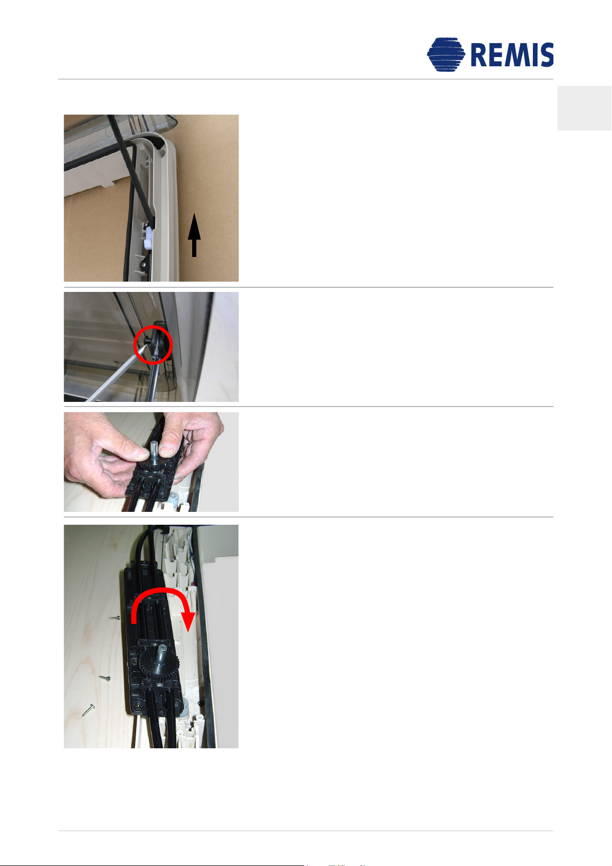
B23:
Zur Montage des Niederhalters tauschen Sie die weiße
Unterlegscheibe gegen die im Lieferumfang enthaltene Di-
stanzhülse Ø8x6mm aus. Achten Sie darauf, dass die Zug-
feder vorhanden bleiben.
Montieren Sie den Niederhalter mit den beiden Schrau-
ben Ø3,5x40mm. Führen Sie dabei die hintere der beiden
Schrauben durch die Öse der Zugfeder (die Schraube muss
durch die Feder geführt werden) und setzen Sie sie an-
schließend auf die weiße Unterlegscheibe auf.
Ziehen Sie die Schraube handfest an, sodass die Zugfeder
nicht eingequetscht wird. Ziehen Sie zusätzlich beim An-
schrauben den Verriegelungshaken von Hand nach vorne.
B22 (Wiederanbringen des Sicherungsrings (befindet sich
am Getriebe)):
Drücken Sie zuletzt den Sicherungsring beispielsweise mit
einem Schraubendreher an die Welle.
B22
B23
B24
B25
B26
B27
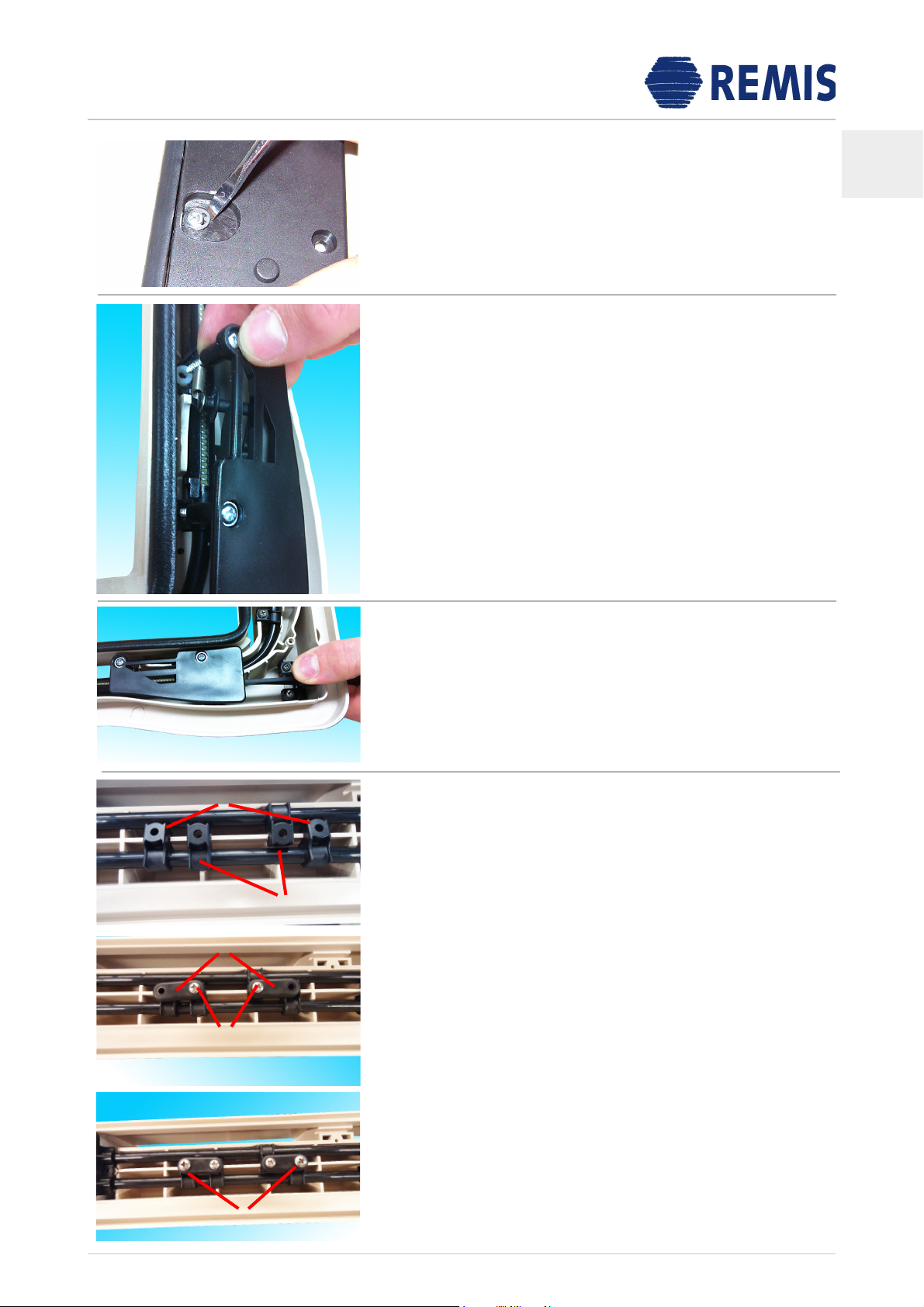
B25-B30:
Die zusätzlichen Schlauchbefestigungen bei der Größe
700x500 werden gemäß der nachfolgenden Bilder mon–
tiert. Die Bilder B25–B27 zeigen die Anordnung auf der
rechten Seite neben dem Getriebedeckel. Die Bilder B28–
B30 zeigen die Montage der linken Seite.
Die Schlauchhalter (4) werden hierbei mit der Schraub–
gegenplatte (3) und der Schraube 3,5x19mm (2) in dem
Schraubdom verschraubt. Anschließend wird die Schraub–
gegenplatte (3) mit dem zusätzlichen Schlauchhalter (5)
und der Schraube 4,0x9,5mm (1) verschraubt.
4
3
2
1
5
D