manuals.online logo
Brands
  1. Home
  2. •
  3. Brands
  4. •
  5. REMIS
  6. •
  7. Automobile Accessories
  8. •
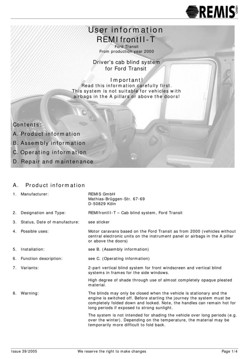
  9. REMIS REMIfrontII-S Operation manual

REMIS REMIfrontII-S Operation manual

Issue: 34/2005 We reserve the right to make changes Page 1/5
User information
REMIfrontII-S
Mercedes Sprinter
From production year 2000
Driver's cab blind system
for Mercedes Sprinter
Important!
Read this information carefully first.
This system is not suitable for vehicles with
airbags in the A pillars or above the doors!
Contents:
A. Product information
B. Assembly information
C. Operating information
D. Repair and maintenance
A. Product information
1. Manufacturer: REMIS GmbH
Mathias-Brüggen-Str. 67-69
D-50829 Köln
2. Designation and Type: REMIfrontII-S – Cab blind system, Mercedes Sprinter
3. Status, Date of manufacture: see sticker
4. Possible uses: Motor caravans based on the Mercedes Sprinter as from 2000 (vehicles
without airbags above the a pillar or above the doors)
5. Installation: see B. (Assembly information)
6. Function description: see C. (Operating information)
7. Variants: 2-part vertical blind system for front windscreen and vertical blind
systems in frames for the side windows.
High degree of shade through use of almost completely opaque pleated
material.
8. Warning: The blinds may only be closed when the vehicle is stationary and the
engine is switched off. Before starting the journey the system must be
completely folded down and locked. Note, the handles can remain hot for
lon
g
p
eriods if ex
p
osed to stron
g
sunli
g
ht.
The system is not intended for shading the vehicle over long periods
(e.g. over the winter). Depending on the temperature, the material may
be temporarily more difficult to fold back.
REMIfrontII-S User information
Issue: 34/2005 We reserve the right to make changes Page 2/5
C. Assembly information
We recommend that the blind system is installed by a specialist workshop !
No liability or warranty is accepted in cases of incorrect assembly or installation.
Step 1: (Check scope of delivery)
B1:
1 Front system
-Cover
A-pillar left/right
-Guide tubes top
(1515mm) &
bottom
(1585mm)
-Top cover, left
and right
2 Side system
-driver's side
-passenger side
B2:
Front blind
- 2 tube carriers
- 4 screws 4.2x13
- 6 screws 3.9x16
- 2 screws 2.9x16
Side blind
- 12 screws
3.5x19
Step 2: (Assemble guide tubes, for trade only!)
B3-B4:
If the top and
bottom guide tubes
are delivered
separately, they
must be joined with
the adhesive
supplied with the kit.
B5:
The adhesive is
applied into the
guide tube at the
end without the
thread. Use
sufficient to fill the
front part of the
opening generously.
B6:
The guide tube with pin is now pushed rapidly into the other tube. Allow the joined
tubes to harden for 10-15 minutes!
Important: Always link pairs of the same length!
Step 3: (Mount front system)
B7:
Remove door seal
from area of the
left A-pillar cover.
B8:
Push fingers
between A-pillar
and roof covering
and pull out of the
metal.
B9:
The A-pillar cover
can now be lifted
off upwards.
B10:
For ease of
assembly, a pieces
should be cut out
of the roof
covering, as
shown.
B11:
The bottom lug of
the "left A-pillar
cover" is fed into
the bottom
opening of the
metal.
B12-13:
Press the bracket
on the cover into
the top opening of
the metal.
B8
B9
B10
B13
B6
B12
B7
B11
B3
B4
B5 B5
REMIfrontII-S User information
Issue: 34/2005 We reserve the right to make changes Page 3/5
B14:
Press the cover on
firmly. If it does
not sit correctly,
pull off again and
either cut off more
of the roof
covering or push
the cables which
run behind
somewhat to the
side.
B15:
Press the rubber
door seal on again.
B16:
To make the next steps easier, remove
the mirror. The mirror must be pulled
out upwards.
B17:
Screw top guide
tube (plug) onto
the right A-pillar
cover.
(1x screw 2.9x16)
B18
Screw top guide
tube (plug) onto
the right A-pillar
cover.
(1x screw 2.9x16)
B19:
Push tube carrier
onto top guide
tube.
B20:
Push tube carrier
onto bottom guide
tube.
B21:
Mount the right A-
pillar cover just
like the left cover
(B7-14).
B22:
Screw the bottom
guide tube into the
thread of the left A
pillar cover.
B23:
Repeat process for
top guide tube.
B24-25:
Lay right section of
top cover with the
contour against
the A-pillar cover
and screw on.
(3x screws 3.9x16)
B26-27:
Push left section of
cover into the right
cover and lay with
the contour
against the A-pillar
cover and screw
on (3x screws
3.9x16).
B28:
Stick on the tube
carrier in the cover
in line with the
mirror carrier.
B29:
Screw tube carrier
tight.
(2x screws 4.2x13)
B30:
Pull together front
blind in order to
position tube
carrier in centre.
B31:
Straighten tube
carrier and stick
on.
B32:
Screw tube carrier
fast.
(2x screws 4.2x13)
B33:
Re-hang mirror.
B26
B19
B20
B21
B22
B30
B33
B25
B27
B28
B29
REMIfrontII-S User information
Issue: 34/2005 We reserve the right to make changes Page 4/5
Step 4: (Mount the side system)
B34:
Insert frame and
press against door.
B35:
Screw on frame.
(6x screws
3.5x19).
D. Operating information
Front system:
C1:
Push button up to
unlock front blind.
C2:
Pull handles from
left and right
towards the middle
of the windscreen.
C3:
Bring handles
together in the
middle, magnetic
catch locks blinds
automatically.
Side system:
C4:
To open:
Release handle
from rest position
by tilting and
pulling lightly.
To close:
Latch in handle by
pressing onto
frame.
C5:
Bring handle up to
stop rail, magnetic
catch locks
automatically.
C6:
To open:
Release handle
from rest position
by tilting and
pulling lightly.
To close:
Latch in handle by
pressing onto
frame.
C7:
Bring handle up to
stop rail, magnetic
catch locks
automatically.
C4
C5
C6C7
REMIfrontII-S User information
Issue: 34/2005 We reserve the right to make changes Page 5/5
E. Repair and maintenance
1. Care: Do not use aggressive cleaners (solvents and abrasives). Clean the frame
of the front and side system with a damp cloth and mild soap solution.
Clean pleated material with a soft brush or a damp cloth.
2. Maintenance/repair: The system is designed to be maintenance-free.
3. Where to keep the documents: The user information with the operating and assembly instructions should
be kept in the vehicle if possible so that they are at hand when needed.
4. Spare parts: Spare parts are available from your specialist dealer.
C3

Other REMIS Automobile Accessories manuals

REMIS REMITop Vario II User manual

REMIS

REMIS REMITop Vario II User manual

REMIS REMIfrontII-T Operation manual

REMIS

REMIS REMIfrontII-T Operation manual

REMIS REMITop Vario II User manual

REMIS

REMIS REMITop Vario II User manual

REMIS REMIcare Van User manual

REMIS

REMIS REMIcare Van User manual

REMIS REMITop Vario II Guide

REMIS

REMIS REMITop Vario II Guide

Popular Automobile Accessories manuals by other brands

SBS TEEARSETBT820K user manual

SBS

SBS TEEARSETBT820K user manual

iDataLink maestro Rr manual

iDataLink

iDataLink maestro Rr manual

Aries 2051179 installation manual

Aries

Aries 2051179 installation manual

WALMEC 2159 Mounting instructions

WALMEC

WALMEC 2159 Mounting instructions

Mobileye Mobileye 6 quick start

Mobileye

Mobileye Mobileye 6 quick start

Yakima K1200 instructions

Yakima

Yakima K1200 instructions

Defender 121 manual

Defender

Defender 121 manual

SVC GROUP VTZ 001-408 Fitting instructions

SVC GROUP

SVC GROUP VTZ 001-408 Fitting instructions

Global Target Enterprise CK802D quick guide

Global Target Enterprise

Global Target Enterprise CK802D quick guide

Brodit ProClip 804729 installation instructions

Brodit

Brodit ProClip 804729 installation instructions

hager XEV1R22T2 Series operating instructions

hager

hager XEV1R22T2 Series operating instructions

Thule 265 manual

Thule

Thule 265 manual

Fishbone Offroad FB23083 installation instructions

Fishbone Offroad

Fishbone Offroad FB23083 installation instructions

TrailFX TFX5521 quick start guide

TrailFX

TrailFX TFX5521 quick start guide

Cequent 24942 installation instructions

Cequent

Cequent 24942 installation instructions

CYBEX SIRONA M2 i-SIZE user guide

CYBEX

CYBEX SIRONA M2 i-SIZE user guide

XRACK Fixed Wing Base Owner's manual and safety instructions

XRACK

XRACK Fixed Wing Base Owner's manual and safety instructions

BENDIX Wingman FLR20 installation instructions

BENDIX

BENDIX Wingman FLR20 installation instructions

manuals.online logo
manuals.online logoBrands
  • About & Mission
  • Contact us
  • Privacy Policy
  • Terms and Conditions

Copyright 2025 Manuals.Online. All Rights Reserved.