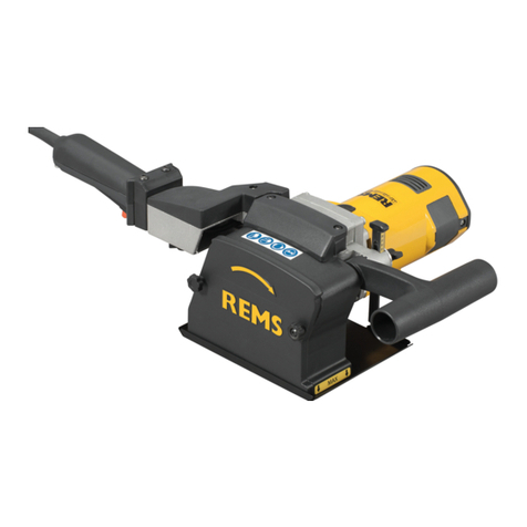
REMS Curvo User manual

REMS Curvo
REMS Curvo 50
REMS Akku-Curvo
REMS Sinus
deu Betriebsanleitung
eng Instruction Manual
fra Notice d’utilisation
ita Istruzioni d’uso
spa Instrucciones de servicio
nld Handleiding
swe Bruksanvisning
nno Bruksanvisning
dan Brugsanvisning
fin Käyttöohje
por Manual de instruções
pol ,QVWUXNFMDREVáXJL
ces 1iYRGNSRXåLWt
slk Návod na obsluhu
hun .H]HOpVLXWDVtWiV
hrv Upute za rad
srp Uputstvo za rad
slv Navodilo za uporabo
ron Manual de utilizare
rus Ɋɭɤɨɜɨɞɫɬɜɨɩɨɷɤɫɩɥɭɚɬɚɰɢɢ
ell ȅįȘȖȓİȢȤȡȒıȘȢ
tur .XOODQÕPNÕODYX]X
bul Ɋɴɤɨɜɨɞɫɬɜɨɡɚɟɤɫɩɥɨɚɬɚɰɢɹ
lit 1DXGRMLPRLQVWUXNFLMD
lav Lietošanas instrukcija
est Kasutusjuhend
REMS GmbH & Co KG
Maschinen- und Werkzeugfabr k
Stuttgarter Straße 83
D-71332 Waiblingen
Telefon +49 7151 1707-0
Telefax +49 7151 1707-110
www.rems.de
05/2013 586003 R

REMS Curvo 50
1 3 4 7 9
8
10 11
12
5 6
REMS Curvo
110
2
3 4 7 9
8
5
6
R88 R114
R140
Fig. 1a
Fig. 1b
R40–R77
R98
R102
13
14
15
16

REMS Akku-Curvo
Fig. 1c
110
2
3 4 7 8 9 17
5
6
18
R88 R114
R140
R40–R77
R98
R102

Fig. 2 Curvo / Akku-Curvo
Ø mm R mm X mm
10 R 40 45
12 R 45 49
14 R 50 53
15 R 55 56
16 R 60 62
17 R 56 60
18 R 70 75
20 R 75 80
22 R 77 81
22 R 88 91
24 R 75 85
25 R 98 103
26 R 98 108
28 R 102 108
28 R 114 120
30 R 98 105
32 R 98 110
32 R 114 121
35 R 140 150
40 R 140 148
3/8” R 43 48
1/2” R 52 60
5/8” R 63 70
3/4” R 75 82
7/8” R 98 107
1” R 101 112
11/8” R 115 117
11/4” R 133 145
13/8” R 140 150
Curvo 50
35 R 100 105
42 R 140 155
1” R 100 105
11/4” R 140 150

Originalbetriebsanleitung
Fig. 1–2
1 Biegesegment
2 Vierkant
3 Gleitstück
4 Steckbolzen
5 linke Aufnahmebohrung
6 rechte Aufnahmebohrung
7 Stellring / Schieber
8 Tippschalter
9 Motorgriff
10 Mitnehmer
11 Abstützung 35–50
12 Vierkant 35– 50
13 Abstützung 10–40
14 Vierkant 10– 40
15 Abstützung unten
16 Arretierbolzen
17 Akku
18 Schnellladegerät
$OOJHPHLQH6LFKHUKHLWVKLQZHLVH
WARNUNG
Lesen Sie alle Sicherheitshinweise und Anweisungen. Versäumnisse bei der
Einhaltung der Sicherheitshinweise und Anweisungen können elektrischen Schlag,
Brand und/oder schwere Verletzungen verursachen.
Bewahren Sie alle Sicherheitshinweise und Anweisungen für die Zukunft auf.
Der in den Sicherheitshinweisen verwendete Begriff „Elektrowerkzeug“ bezieht sich
auf netzbetriebene Elektrowerkzeuge (mit Netzkabel) und auf akkubetriebene
Elektrowerkzeuge (ohne Netzkabel).
1) Arbeitsplatzsicherheit
a) Halten Sie Ihren Arbeitsbereich sauber und gut beleuchtet. Unordnung und
unbeleuchtete Arbeitsbereiche können zu Unfällen führen.
E $UEHLWHQ6LHPLWGHP(OHNWURZHUN]HXJQLFKWLQH[SORVLRQVJHIlKUGHWHU
8PJHEXQJLQGHUVLFKEUHQQEDUH)OVVLJNHLWHQ*DVHRGHU6WlXEHEH¿QGHQ
Elektrowerkzeuge erzeugen Funken, die den Staub oder die Dämpfe entzünden
können.
c) Halten Sie Kinder und andere Personen während der Benutzung des Elek-
trowerkzeugs fern. Bei Ablenkung können Sie die Kontrolle über das Gerät
verlieren.
2) Elektrische Sicherheit
D 'HU$QVFKOXVVVWHFNHUGHV(OHNWURZHUN]HXJVPXVVLQGLH6WHFNGRVHSDVVHQ
Der Stecker darf in keiner Weise verändert werden. Verwenden Sie keine
Adapterstecker gemeinsam mit schutzgeerdeten Elektrowerkzeugen. Unverän-
derte Stecker und passende Steckdosen verringern das Risiko eines elektrischen
Schlages.
E 9HUPHLGHQ6LH.|USHUNRQWDNWPLWJHHUGHWHQ2EHUÀlFKHQZLHYRQ5RKUHQ
+HL]XQJHQ+HUGHQXQG.KOVFKUlQNHQ Es besteht ein erhöhtes Risiko durch
elektrischen Schlag, wenn Ihr Körper geerdet ist.
c) Halten Sie Elektrowerkzeuge von Regen oder Nässe fern. Das Eindringen
von Wasser in ein Elektrowerkzeug erhöht das Risiko eines elektrischen Schlages.
G =ZHFNHQWIUHPGHQ6LHGDV.DEHOQLFKWXPGDV(OHNWURZHUN]HXJ]XWUDJHQ
DXI]XKlQJHQRGHUXPGHQ6WHFNHUDXVGHU6WHFNGRVH]X]LHKHQ+DOWHQ6LH
GDV.DEHOIHUQYRQ+LW]HgOVFKDUIHQ.DQWHQRGHUVLFKEHZHJHQGHQ
Geräteteilen. Beschädigte oder verwickelte Kabel erhöhen das Risiko eines
elektrischen Schlages.
H :HQQ6LHPLWHLQHP(OHNWURZHUN]HXJLP)UHLHQDUEHLWHQYHUZHQGHQ6LH
QXU9HUOlQJHUXQJVNDEHOGLHDXFKIUGHQ$XHQEHUHLFKJHHLJQHWVLQG Die
Anwendung eines für den Außenbereich geeigneten Verlängerungskabels
verringert das Risiko eines elektrischen Schlages.
I :HQQGHU%HWULHEGHV(OHNWURZHUN]HXJVLQIHXFKWHU8PJHEXQJQLFKW
YHUPHLGEDULVWYHUZHQGHQ6LHHLQHQ)HKOHUVWURPVFKXW]VFKDOWHU Der Einsatz
eines Fehlerstromschutzschalters vermindert das Risiko eines elektrischen
Schlages.
3) Sicherheit von Personen
D 6HLHQ6LHDXIPHUNVDPDFKWHQ6LHGDUDXIZDV6LHWXQXQGJHKHQ6LHPLW
9HUQXQIWDQGLH$UEHLWPLWHLQHP(OHNWURZHUN]HXJ%HQXW]HQ6LHNHLQ(OHN-
WURZHUN]HXJZHQQ6LHPGHVLQGRGHUXQWHUGHP(LQÀXVVYRQ'URJHQ
$ONRKRORGHU0HGLNDPHQWHQVWHKHQ Ein Moment der Unachtsamkeit beim
Gebrauch des Elektrowerkzeugs kann zu ernsthaften Verletzungen führen.
E 7UDJHQ6LHSHUV|QOLFKH6FKXW]DXVUVWXQJXQGLPPHUHLQH6FKXW]EULOOH
Das Tragen persönlicher Schutzausrüstung, wie Staubmaske, rutschfeste Sicher-
heitsschuhe, Schutzhelm, oder Gehörschutz, je nach Art und Einsatz des Elek-
trowerkzeugs, verringert das Risiko von Verletzungen.
F 9HUPHLGHQ6LHHLQHXQEHDEVLFKWLJWH,QEHWULHEQDKPH9HUJHZLVVHUQ6LH
VLFKGDVVGDV(OHNWURZHUN]HXJDXVJHVFKDOWHWLVWEHYRU6LHHVDQGLH
6WURPYHUVRUJXQJXQGRGHUGHQ$NNXDQVFKOLHHQHVDXIQHKPHQRGHU
tragen. Wenn Sie beim Tragen des elektrischen Gerätes den Finger am Schalter
haben oder das Gerät eingeschaltet an die Stromversorgung anschließen, kann
dies zu Unfällen führen.
G (QWIHUQHQ6LH(LQVWHOOZHUN]HXJHRGHU6FKUDXEHQVFKOVVHOEHYRU6LHGDV
Elektrowerkzeug einschalten. Ein Werkzeug oder Schlüssel, der sich in einem
drehenden Geräteteil be¿ndet, kann zu Verletzungen führen.
H 9HUPHLGHQ6LHHLQHDEQRUPDOH.|USHUKDOWXQJ6RUJHQ6LHIUHLQHQVLFKHUHQ
Stand und halten Sie jederzeit das Gleichgewicht. Dadurch können Sie das
Elektrowerkzeug in unerwarteten Situationen besser kontrollieren.
f) Tragen Sie geeignete Kleidung. Tragen Sie keine weite Kleidung oder
6FKPXFN+DOWHQ6LH+DDUH.OHLGXQJXQG+DQGVFKXKHIHUQYRQVLFK
bewegenden Teilen. Lockere Kleidung, Schmuck oder lange Haare können von
sich bewegenden Teilen erfasst werden.
J :HQQ6WDXEDEVDXJXQGDXIIDQJHLQULFKWXQJHQPRQWLHUWZHUGHQN|QQHQ
YHUJHZLVVHUQ6LHVLFKGDVVGLHVHDQJHVFKORVVHQVLQGXQGULFKWLJYHUZHQGHW
werden. Verwendung einer Staubabsaugung kann Gefährdungen durch Staub
verringern.
4) Verwendung und Behandlung des Elektrowerkzeugs
a) Überlasten Sie das Gerät nicht. Verwenden Sie für Ihre Arbeit das dafür
EHVWLPPWH(OHNWURZHUN]HXJ Mit dem passenden Elektrowerkzeug arbeiten
Sie besser und sicherer im angegebenen Leistungsbereich.
E %HQXW]HQ6LHNHLQ(OHNWURZHUN]HXJGHVVHQ6FKDOWHUGHIHNWLVW Ein Elek-
trowerkzeug, das sich nicht mehr ein- oder ausschalten lässt, ist gefährlich und
muss repariert werden.
F =LHKHQ6LHGHQ6WHFNHUDXVGHU6WHFNGRVHXQGRGHUHQWIHUQHQ6LHGHQ$NNX
EHYRU6LH*HUlWHHLQVWHOOXQJHQYRUQHKPHQ=XEHK|UWHLOHZHFKVHOQRGHU
das Gerät weglegen. Diese Vorsichtsmaßnahme verhindert den unbeabsichtigten
Start des Elektrowerkzeugs.
G %HZDKUHQ6LHXQEHQXW]WH(OHNWURZHUN]HXJHDXHUKDOEGHU5HLFKZHLWHYRQ
.LQGHUQDXI/DVVHQ6LH3HUVRQHQGDV*HUlWQLFKWEHQXW]HQGLHPLWGLHVHP
nicht vertraut sind oder diese Anweisungen nicht gelesen haben. Elektro-
werkzeuge sind gefährlich, wenn sie von unerfahrenen Personen benutzt werden.
H 3ÀHJHQ6LHGDV(OHNWURZHUN]HXJPLW6RUJIDOW.RQWUROOLHUHQ6LHREEHZHJ-
OLFKH*HUlWHWHLOHHLQZDQGIUHLIXQNWLRQLHUHQXQGQLFKWNOHPPHQRE7HLOH
JHEURFKHQRGHUVREHVFKlGLJWVLQGGDVVGLH)XQNWLRQGHV(OHNWURZHUN]HXJV
EHHLQWUlFKWLJWLVW/DVVHQ6LHEHVFKlGLJWH7HLOHYRUGHP(LQVDW]GHV*HUlWHV
reparieren. Viele Unfälle haben ihre Ursache in schlecht gewarteten Elektro-
werkzeugen.
f) Halten Sie Schneidwerkzeuge scharf und sauber. Sorgfältig gepÀegte Schneid-
werkzeuge mit scharfen Schneidkanten verklemmen sich weniger und sind leichter
zu führen.
J 9HUZHQGHQ6LH(OHNWURZHUN]HXJ=XEHK|U(LQVDW]ZHUN]HXJHXVZHQWVSUH-
chend diesen Anweisungen. Berücksichtigen Sie dabei die Arbeitsbedin-
gungen und die auszuführende Tätigkeit. Der Gebrauch von Elektrowerkzeugen
für andere als die vorgesehenen Anwendungen kann zu gefährlichen Situationen
führen.
5) Verwendung und Behandlung des Akkuwerkzeugs
D /DGHQ6LHGLH$NNXVQXULQ/DGHJHUlWHQDXIGLHYRP+HUVWHOOHUHPSIRKOHQ
werden. Für ein Ladegerät, das für eine bestimmte Art von Akkus geeignet ist,
besteht Brandgefahr, wenn es mit anderen Akkus verwendet wird.
b) Verwenden Sie nur die dafür vorgesehenen Akkus in den Elektrowerkzeugen.
Der Gebrauch von anderen Akkus kann zu Verletzungen und Brandgefahr führen.
F +DOWHQ6LHGHQQLFKWEHQXW]WHQ$NNXIHUQYRQ%URNODPPHUQ0Q]HQ
6FKOVVHOQ1lJHOQ6FKUDXEHQRGHUDQGHUHQNOHLQHQ0HWDOOJHJHQVWlQGHQ
die eine Überbrückung der Kontakte verursachen könnten. Ein Kurzschluss
zwischen den Akkukontakten kann Verbrennungen oder Feuer zur Folge haben.
G %HLIDOVFKHU$QZHQGXQJNDQQ)OVVLJNHLWDXVGHP$NNXDXVWUHWHQ9HUPHLGHQ
6LHGHQ.RQWDNWGDPLW%HL]XIlOOLJHP.RQWDNWPLW:DVVHUDEVSOHQ:HQQ
GLH)OVVLJNHLWLQGLH$XJHQNRPPWQHKPHQ6LH]XVlW]OLFKlU]WOLFKH+LOIH
in Anspruch. Austretende AkkuÀüssigkeit kann zu Hautreizungen oder Verbren-
nungen führen.
6) Service
D /DVVHQ6LH,KU(OHNWURZHUN]HXJQXUYRQTXDOL¿]LHUWHP)DFKSHUVRQDOXQG
QXUPLW2ULJLQDO(UVDW]WHLOHQUHSDULHUHQ Damit wird sichergestellt, dass die
Sicherheit des Geräts erhalten bleibt.
Sicherheitshinweise für elektrische Rohrbieger
WARNUNG
Lesen Sie alle Sicherheitshinweise und Anweisungen. Versäumnisse bei der
Einhaltung der Sicherheitshinweise und Anweisungen können elektrischen Schlag,
Brand und/oder schwere Verletzungen verursachen.
Bewahren Sie alle Sicherheitshinweise und Anweisungen für die Zukunft auf.
Ɣ
Persönliche Schutzausrüstung benutzen (Schutzbrille).
Ɣ
Abnorme Körperhaltung vermeiden, nicht zu weit vorbeugen.
Ɣ
Beim Biegen nicht zwischen Rohr und Biegesegment fassen. Quetschgefahr !!
Ɣ
Halten sie Haare und Kleidung fern von sich bewegenden Teilen.
Ɣ
Nur Arbeiten durchführen, für welche die Maschine vorgesehen ist.
Ɣ
Während der Arbeiten dritte Personen vom Arbeitsbereich fernhalten.
Ɣ
Die Antriebsmaschinen entwickeln eine sehr hohe Biegekraft. Deshalb besonders
vorsichtig sein.
Ɣ
Die Akku’s Ni-Cd bzw. Li-Ion sind in der Antriebsmaschine nicht tauschbar.
Ɣ
Sollte der Austausch des Steckers oder Anschlussleitung erforderlich sein, so ist
dies nur vom Hersteller oder seines Kundendienstes auszuführen.
Sicherheitshinweise für Akkus
WARNUNG
Lesen Sie alle Sicherheitshinweise und Anweisungen. Versäumnisse bei der
Einhaltung der Sicherheitshinweise und Anweisungen können elektrischen Schlag,
Brand und/oder schwere Verletzungen verursachen.
Bewahren Sie alle Sicherheitshinweise und Anweisungen für die Zukunft auf.
Ɣ
Akkus dürfen nur bei Temperaturen des Akkus oder Umgebungstemperaturen
–10 °C – +60 °C (14 °F – +40 °F) verwendet werden.
Ɣ
Das Schnellladegerät darf nur bei Temperaturen des Schnellladegerätes oder
Umgebungstemperaturen 0 °C – +40 °C (32 °F – +104 °F) verwendet werden.
Ɣ
Aufgedruckte Sicherheitshinweise auf Akku und Ladegerät beachten.
Ɣ
Schadhafte Akkus nicht im normalen Hausmüll entsorgen. Übergeben Sie
schadhafte Akkus einer autorisierten REMS Vertrags-Kundendienstwerkstatt
oder einem anerkannten Entsorgungsunternehmen.
Ɣ
Akku vor Nässe schützen.
Ɣ
Bei Aufbewahrung desAkkus außerhalb des Werkzeugs bzw. Schnellladegerätes,
Akku-Kontakte abdecken.
Ɣ
Akku nicht öffnen. Explosions- und Brandgefahr durch Kurzschluss.
Ɣ
Akku nicht baulich verändern.
Ɣ
Akku nur im Innenbereich verwenden.
Ɣ
Akku auf keinen Fall unter widrigen Umgebungsbedingungen, z.B. brennbare
Gase, Lösungsmittel, Staub, Dämpfe, Nässe, verwenden.
Ɣ
Akku bei Beschädigung des Gehäuses oder der Kontakte nicht verwenden.
Ɣ
Akku nicht in explosionsgefährdeten Bereichen verwenden.
Ɣ
Aufgedruckte Sicherheitshinweise auf Akku und Ladegerät beachten.
6\PEROHUNOlUXQJ
Vor Inbetriebnahme Betriebsanleitung lesen
Elektrowerkzeug entspricht der Schutzklasse II
Umweltfreundliche Entsorgung
CE-Konformitätskennzeichnung
1. Technische Daten
%HVWLPPXQJVJHPlVVH9HUZHQGXQJ
WARNUNG
REMS Curvo und REMS Akku-Curvo sind bestimmt zum kalten Ziehbiegen von
Rohren bis 180°.
REMS Curvo 50 ist bes immt zum kalten Ziehbiegen von Rohren bis 90°.
Alle anderen Verwendungen sind nicht bestimmungsgemäß und daher nicht zulässig.
$UWLNHOQXPPHUQ
REMS Curvo Antriebsmaschine 580000
REMS Akku-Curvo Antriebsmaschine Li-Ion 580002
REMS Curvo 50 Antriebsmaschine 580100
Vierkantmitnehmer 35– 50, Abstützung 35– 50 582110
Vierkantmitnehmer 10– 40, Abstützung 10– 40 582120
Steckbolzen 582036
Schnellladegerät Li-Ion/Ni-Cd 230 V, 50 – 60 Hz, 65 W 571560
REMS Akku Li-Ion 18 V, 2,6 Ah 565215
REMS Akku Li-Ion 18 V, 3,5 Ah 565217
REMS Biegespray, 400 ml 140120
1.2. Arbeitsbereich
Beim fachgerechten Kaltbiegen dürfen keine Anrisse oder Falten auftreten.
Rohrqualitäten und -abmessungen, die dies nicht gewährleisten, sind zum
Biegen mit REMS Curvo, REMS Curvo 50 und REMS Akku-Curvo nicht geeignet.
Harte Kupferrohre sind nach DIN EN 1057 bis Ø 18 mm kalt biegbar, und es
sind Mindestbiegeradien einzuhalten. Biegesegmente und Gleitstücke für
größere Biegeradien sind lieferbar.
REMS Curvo
Ɣ
Harte, halbharte, weiche Kupferrohre, auch dünnwandig, Ø 10 –35 mm, Ǫ–1Ǫ”.
Ɣ
Weiche ummantelte Kupferrohre, auch dünnwandig, Ø 10–18 mm.
Ɣ
Nichtrostende Stahlrohre der Press¿tting-Systeme Ø 12 – 28 mm.
Ɣ
Ummantelte C-Stahlrohre der Press¿tting-Systeme Ø 12 – 28 mm.
Ɣ
Weiche Präzisionsstahlrohre Ø 10–30 mm, Wanddicke 1,5 mm.
Ɣ
Stahlrohre DIN EN 10255 (DIN 2440) ¼” – ¾”.
Ɣ
Elektroinstallationsrohre DIN EN 50086 Ø 16 – 32 mm.
Ɣ
Verbundrohre Ø 14–40 mm.
Größter Biegewinkel 180°
REMS Curvo 50
Ɣ
Stahlrohre DIN EN 10255 (DIN 2440) ¼” – 1¼”.
Ɣ
Harte, halbharte und weiche Kupferrohre Ø 10 – 42 mm.
Ɣ
Dünnwandige Kupferrohre Ø 10 – 35 mm.
Ɣ
Nichtrostende Stahlrohre der Press¿tting-Systeme Ø 12 – 42 mm.
Ɣ
Verbundrohre Ø 14–50 mm.
Größter Biegewinkel 90°
REMS Akku-Curvo
Ɣ
Harte, halbharte, weiche Kupferrohre, auch dünnwandig, Ø 10 –28 mm, Ǫ–1ǩ”.
Ɣ
Weiche ummantelte Kupferrohre, auch dünnwandig Ø 10–18 mm.
Ɣ
Nichtrostende Stahlrohre der Press¿tting-Systeme Ø 12 – 28 mm.
Ɣ
Ummantelte C-Stahlrohre der Press¿tting-Systeme Ø 12 – 28 mm.
Ɣ
Weiche Präzisionsstahlrohre Ø 10–28 mm, Wanddicke 1,5 mm.
Ɣ
Stahlrohre DIN EN 10255 Ø ¼ – ½”.
Ɣ
Elektroinstallationsrohre DIN EN 50086 Ø 16 – 25 mm.
Ɣ
Verbundrohre Ø 14–32 mm
Größter Biegewinkel 180°
1.3. Drehzahl Curvo Curvo 50 Akku-Curvo
Drehzahl stufenlos
einstellbar 0…4 minʚï 0…1 minʚï 0…3,33 minʚï
1.4. Elektrische Daten
REMS Curvo, 230 V, 1~, 50 – 60 Hz; 1000 W; 4,8 A oder
REMS Curvo 50 110 V, 1~, 50 – 60 Hz; 1000 W; 9,6 A,
Aussetzbetrieb S3 15% 2/14 min,
schutzisoliert, funkentstört.
Schutzklasse IP 20
REMS Akku-Curvo 18 V =
Schnellladegerät Input 230 V~; 50–60 Hz; 65 W
(1 h) Output 12–18 V =
$EPHVVXQJHQPP&XUYR &XUYR $NNX&XUYR
L×B×H: 585×215×140 640×240×95 540×280×140
(23”×8½”×5½”) (25”×9½”×3¾”) (21¼”×11”×5½”)
1.6. Gewichte
Antriebsgerät 8,3 kg 16,9 kg 9 kg (mit Akku)
(18,3 lb) (37,3 lb) (19,8 lb)
Biegesegmente 0,2..1,6 kg 4,44..7,8 kg 0,2..1,6 kg
(½..3½ lb) (9,8..17,2 lb) (½..3½ lb)
Gleitstücke 0,1..0,2 kg 0,25..0,42 kg 0,1..0,2 kg
(¼..½ lb) (0,55..0,9 lb) (¼..½ lb)
Steckbolzen 0,4 kg (Ǭlb) 0,4 kg (Ǭlb) 0,4 kg (Ǭlb)
REMS Akku Li-Ion
18 V, 2,6 Ah 0,63 kg (1,4 lb)
18 V, 3,5 Ah 0,64 kg (1,4 lb)
/lUPLQIRUPDWLRQ
Arbeitsplatzbezogener
Emissionswert 82 dB (A) 90 dB (A) 90 dB (A)
Schalldruckpegel LpA = 86 dB
Schalleistungspegel LwA = 97 dB
Unsicherheit K = 3 dB
1.8. Vibrationen
Gewichteter Effektivwert der
Beschleunigung 2,5 m/s² 2,5 m/s² 2,5 m/s²
Der angegebene Schwingungsemissionswert wurde nach einem genormten
Prüfverfahren gemessen und kann zum Vergleich mit einem anderen Gerät
verwendet werden. Der angegebene Schwingungsemissionswert kann auch
zu einer einleitenden Einschätzung der Aussetzung verwendet werden.
VORSICHT
Der Schwingungsemissionswert kann sich während der tatsächlichen Benutzung
des Gerätes von dem Angabewert unterscheiden, abhängig von der Art und
Weise, in der das Gerät verwendet wird. In Abhängigkeit von den tatsächlichen
Benutzungsbedingungen (Aussetzbetrieb) kann es erforderlich sein, Sicher-
heitsmaßnahmen zum Schutz der Bedienperson festzulegen.
,QEHWULHEQDKPH
2.1. Elektrischer Anschluss
WARNUNG
Netzspannung beachten! Vor Anschluss der Antriebsmaschine bzw. des
Schnellladegerätes prüfen, ob die auf dem Leistungsschild angegebene Span-
nung der Netzspannung entspricht. Auf Baustellen, in feuchter Umgebung oder
bei vergleichbaren Aufstellarten das elektrische Gerät nur über eine 30 mA-Fehler-
strom-Schutzeinrichtung (FI-Schalter) am Netz betreiben.
Der mit REMS Akku-Curvo gelieferte Akku sowie Ersatzakkus sind ungeladen.
Vor erstem Gebrauch Akku laden. Zum Laden nur REMS Schnellladegerät
(Art.-Nr. 571560) verwenden.
Akkus
HINWEIS
Akku immer senkrecht in die Antriebsmaschine bzw. in das Schnellladegerät
einführen. Schräges Einführen beschädigt die Kontakte und kann zu einem
Kurzschluss führen, wodurch der Akku beschädigt wird.
Tiefentladung durch Unterspannung
Eine Mindestspannung darf bei Akkus Li-Ion nicht unterschritten werden, da
sonst der Akku durch „Tiefentladung“ beschädigt werden kann. Die Zellen der
REMS Akkus Li-Ion sind bei Auslieferung auf ca. 40 % vorgeladen. Deshalb
müssen die Akkus Li-Ion vor Gebrauch geladen und regelmäßig nachgeladen
werden. Wird diese Vorschrift der Zellen-Hersteller missachtet, kann der Akku
Li-Ion durch Tiefen ladung beschädigt werden.
Tiefentladung durch Lagerung
Wird ein relativ niedrig geladener Akku Li-Ion gelagert, kann er bei längerer
Lagerung durch Selbstentladung tiefentladen und damit beschädigt werden.
Akkus Li-Ion müssen deshalb vor Lagerung geladen und spätestens alle sechs
Monate nachgeladen und vor erneuter Belastung unbedingt nochmals aufge-
laden werden.

HINWEIS
9RU*HEUDXFK$NNXODGHQ$NNXV/L,RQUHJHOPlLJQDFKODGHQXP7LHI-
HQWODGXQJ]XYHUPHLGHQ%HL7LHIHQWODGXQJZLUGGHU$NNXEHVFKlGLJW
1 2
Zum Laden nur REMS Schnellladegerät verwenden. Neue und längere Zeit
nicht benutzte Akkus Li-Ion erreichen erst nach mehreren Ladungen die volle
Kapazität. Nicht wiederauÀadbare Batterien dürfen nicht geladen werden.
6FKQHOOODGHJHUlW/L,RQ1L&G$UW1U
Ist der Netzstecker eingesteckt, zeigt die grüne Kontrollleuchte Dauerlicht. Ist
der Akku in das Schnellladegerät eingesteckt, blinkt die grüne Kontrollleuchte,
der Akku wird geladen. Zeigt die grüne Kontrollleuchte Dauerlicht, ist der Akku
geladen. Blinkt die rote Kontrollleuchte, ist derAkku defekt. Zeigt eine Kontrollleuchte
rotes Dauerlicht, liegt die Temperatur des Schnellladegerätes und / oder des
Akkus außerhalb des zulässigen Arbeitsbereiches von 0°C bis +40°C.
HINWEIS
'LH6FKQHOOODGHJHUlWHVLQGQLFKW]XU9HUZHQGXQJLP)UHLHQJHHLJQHW
1LFKWZLHGHUDXÀDGEDUH%DWWHULHQGUIHQQLFKWJHODGHQZHUGHQ'LH$NNX¶V
1L&GE]Z/L,RQVLQGLQGHU$QWULHEVPDVFKLQHQLFKWWDXVFKEDU
2.2. Wahl der Biegewerkzeuge
5(06&XUYR5(06$NNX&XUYR
Der Rohrgröße entsprechendes Biegesegment (1) (Fig. 1) auf Vierkant (2)
aufstecken. Die Aufnahme ist derart gestaltet, dass das Biegesegment nur in
einer Richtung ganz aufgesteckt werden kann. Der Rohrgröße entsprechendes
Gleitstück (3) und den Steckbolzen (4) bereitlegen.
5(06&XUYR±
Der Rohrgröße entsprechendes Biegesegment (1) (Fig. 1) auf Vierkant (12)
aufstecken. Die Aufnahme ist derart gestaltet, dass das Biegesegment nur in
einer Richtung ganz aufgesteckt werden kann. Der Rohrgröße entsprechendes
Gleitstück (3), die Abstützung (11) und den Steckbolzen (4) berei legen.
5(06&XUYR±
Vierkantmitnehmer mit Vierkant (12) abnehmen und Vierkantmitnehmer mit
Vierkant (14) in dieAntriebsmaschine einsetzen. Der Rohrgröße entsprechendes
Biegesegment (1) (Fig. 1) auf Vierkant (14) aufstecken. Die Aufnahme ist derart
gestaltet, daß das Biegesegment nur in einer Richtung ganz aufgesteckt werden
kann. Der Rohrgröße entsprechendes Gleitstück (3), die Abstützung (13) und
den Steckbolzen (4) bereitlegen.
HINWEIS
%HL5(06&XUYRPXVVEHLDOOHQ*U|HQGLH$EVWW]XQJE]Z
REHUKDOEGHV*OHLWXQG%LHJHIRUPVWFNHVDQJHEUDFKWZHUGHQ%LV
HLQVFKOLHOLFKGHU*U|HQ5ô´5PXVV]XVlW]OLFKGLH$EVWW]XQJ
XQWHQDQJHEUDFKWZHUGHQ'LHVHZLUGHLQHUVHLWVDP.DQW%XQGGHU
$EVWW]XQJHLQJHKlQJWDQGHUHUVHLWVPLWGHP$UUHWLHUERO]HQLQ
GHUlXHUVWHQ$XIQDKPHERKUXQJGHU$EVWW]XQJLP*HKlXVHDEJH-
VWHFNWVLHKH
%HLP%LHJHQRKQHGLHVH$EVWW]XQJZLUGGLH$QWULHEVPDVFKLQHEHVFKl-
digt!
3. Betrieb
3.1. Arbeitsablauf
Stellring/Schieber (7) auf »L« (Rücklauf) drehen/schieben. Tippschalter (8)
unter gleichzeitigem Umfassen des Motorgriffes (9) drücken. Das Biegesegment
dreht sich im Uhrzeigersinn in seine Ausgangsstellung gegen Festanschlag.
Tippschalter möglichst vor Erreichen des Festanschlages loslassen, damit
dieser im Auslauf angefahren wird, d. h. die eingebaute Rutschkupplung nicht
unnötig belastet wird. Stellring/Schieber (7) auf »R« (Vorlauf) drehen/schieben.
Rohr in das Biegesegment einlegen, so dass das Rohrende mindestens 10
mm über den Mitnehmer (10) hinausragt. Bei den Rohrgrößen 22 – 50 mm ist
das Rohr in den Radius des Biegesegmentes einzudrücken. Das dazugehörende
Gleitstück (3) anlegen und Steckbolzen (4) in die entsprechende Bohrung am
Gerät einstecken.
HINWEIS
%HL5(06&XUYRPXVVEHLDOOHQ*U|HQGLH$EVWW]XQJE]Z
REHUKDOEGHV*OHLWXQG%LHJHIRUPVWFNHVDQJHEUDFKWZHUGHQ%LV
HLQVFKOLHOLFKGHU*U|HQ5ô´5PXVV]XVlW]OLFKGLH$EVWW]XQJ
XQWHQDQJHEUDFKWZHUGHQ'LHVHZLUGHLQHUVHLWVDP.DQW%XQGGHU
$EVWW]XQJHLQJHKlQJWDQGHUHUVHLWVPLWGHP$UUHWLHUERO]HQLQ
GHUlXHUVWHQ$XIQDKPHERKUXQJGHU$EVWW]XQJLP*HKlXVHDEJH-
VWHFNWVLHKH
%HLP%LHJHQRKQHGLHVH$EVWW]XQJZLUGGLH$QWULHEVPDVFKLQHEHVFKl-
digt!
Dabei ist darauf zu achten, dass der Steckbolzen (4) für die Größen bis 22 mm
in die linke Aufnahmebohrung (5) und ab der Größe 28 mm in die rechte
Aufnahmebohrung (6) eingesteckt wird.
Tippschalter (8) betätigen, das Rohr wird gebogen. Gegen Ende des gewünschten
Bogens Schalter nur noch leicht drücken. Somit kann der Endpunkt langsam
und damit präzis angefahren werden. Auf jedem Biegesegment ist eine Skala
angebracht, die zusammen mit der Markierung auf dem Gleitstück die maßge-
naue Herstellung von Bögen bis 180°/ Curvo 50 bis 90° erlaubt. Dabei ist zu
beachten, daß die verschiedenen Materialien unterschiedlich zurückfedern.
Wird ein 180°/ Curvo 50: 90° Bogen gefertigt und ist die Endstellung erreicht,
wirkt wiederum die Rutschkupplung. Tippschalter sofort loslassen. Stellring/
Schieber (7) auf »L« (Rücklauf) drehen/schieben. Biegesegment durch leichtes
Drücken des Tippschalters (8) einige Grad zurücklaufen lassen bis das Rohr
entspannt ist. Steckbolzen (4) ziehen und das gebogene Rohr entnehmen.
Beim Biegen vor Ort kann zur leichteren Entnahme des gebogenen Rohres
auch das Biegesegment abgezogen werden. Biegesegment immer erst nach
Entnahme des Rohres in Ausgangsstellung zurücklaufen lassen, da sonst der
hergestellte Bogen beschädigt werden kann. Beim Biegen von nichtrostenden
Stahlrohren der Press¿tting-Systeme muss beachtet werden, daß die Markie-
rung am Rohr durch den Mitnehmer (10) nicht im Dichtbereich der Pressver-
bindung liegt.
%LHJHQQDFK0D
Soll ein Bogen an einer bestimmten Stelle am Rohr liegen, so muss entspre-
chend der Rohrgröße eine Längenkorrektur vorgenommen werden. Für einen
90°-Bogen ist das in Fig. 2 angegebene Korrekturmaß X zu berücksichtigen.
Hierbei ist das Sollmaß L um den Betrag X zu kürzen. Soll z. B. bei der Rohr-
größe 22 das Maß L=400 mm betragen, so ist der Maßstrich am Rohr bei
320mm anzubringen. Dieser Strich ist dann – wie in Fig. 2 gezeigt – an der
0-Marke am Biegesegment anzulegen.
*HUlWHKDOWHUXQJ5(06&XUYR5(06$NNX&XUYR
Als Zubehör sind höhenverstellbare Gerätehalterungen auf 3-Bein (Art.-Nr.
586100) bzw. zur Befestigung an der Werkbank (Art.-Nr. 586150) lieferbar.
%LHJHVFKPLHUVWRII
REMS Biegespray (Art.-Nr. 140120) gewährleistet kontinuierlichen Schmier¿lm
für reduzierten Kraftaufwand und gleichmäßiges Biegen. Hochdruckfest,
säurefrei. Ohne FCKW, deshalb Ozon-unschädlich.
4. Instandhaltung
WARNUNG
Vor Instandsetzungs- und Reparaturarbeiten Netzstecker ziehen bzw.
Akku entfernen! Diese Arbeiten dürfen nur von quali¿ziertem Fachpersonal
durchgeführt werden.
4.1. Wartung
REMS Curvo, REMS Curvo 50 und REMS Akku-Curvo sind wartungsfrei. Das
Getriebe läuft in einer Dauerfettfüllung und muss deshalb nicht geschmiert
werden.
4.2. Inspektion/Instandhaltung
Der Motor der REMS Curvo und der REMS Curvo 50 hat Kohlebürsten. Diese
verschleißen und müssen deshalb von Zeit zu Zeit geprüft bzw. erneuert werden.
Hierzu die 4 Schrauben am Motorgriff ca. 3 mm lösen, Motorgriff nach hinten
ziehen und die beiden Deckel am Motorgehäuse abnehmen. Siehe auch 6.
”Störungen.“
5. Anschluss
Bei REMS Akku-Curvo unbedingt darauf achten, dass der Pluspol am Motor
(Kunststoffsockel der Anschlussfahne mit Nase) mit roter Leitung an Schalter-
klemme 1 angeschlossen wird.
6. Störungen
6.1. Störung: Biegesegment bleibt während des Biegens stehen, obwohl
Motor läuft.
Ursache:
Ɣ
Rohr mit zu großer Wandstärke gebogen.
Ɣ
Rutschkupplung abgenutzt.
Ɣ
Kohlebürsten abgenutzt.
Ɣ
Akku leer (REMS Akku-Curvo).
6.2. Störung: Rohrbogen wird unrund.
Ursache:
Ɣ
Falsches Biegesegment oder falsches Gleitstück.
Ɣ
Abgenutztes Gleitstück.
Ɣ
Beschädigtes Rohr.
6.3. Störung: Rohr rutscht während des Biegens aus Mitnehmer (10) heraus.
Ursache:
Ɣ
Mitnehmer verbogen oder abgenutzt.
Ɣ
Rohr ragt zu wenig über Mitnehmer hinaus.
6.4. Störung: Gerät läuft nicht an.
Ursache:
Ɣ
Anschlussleitung defekt.
Ɣ
Gerät defekt.
Ɣ
Akku leer (REMS Akku-Curvo).
7. Entsorgung
Die Antriebsmaschinen dürfen nach ihrem Nutzungsende nicht über den
Hausmüll entsorgt werden. Sie müssen nach den gesetzlichen Vorschriften
ordnungsgemäß entsorgt werden.

g
8. Hersteller-Garantie
Die Garantiezeit beträgt 12 Monate nach Übergabe des Neuproduktes an den
Erstverwender. Der Zeitpunkt der Übergabe ist durch die Einsendung der
Original-Kaufunterlagen nachzuweisen, welche die Angaben des Kaufdatums
und der Produktbezeichnung enthalten müssen. Alle innerhalb der Garantiezeit
auftretenden Funktionsfehler, die nachweisbar auf Fertigungs- oder Material-
fehler zurückzuführen sind, werden kostenlos beseitigt. Durch die Mängelbe-
seitigung wird die Garantiezeit für das Produkt weder verlängert noch erneuert.
Schäden, die auf natürliche Abnutzung, unsachgemäße Behandlung oder
Missbrauch, Missachtung von Betriebsvorschriften, ungeeignete Betriebsmittel,
übermäßige Beanspruchung, zweckfremde Verwendung, eigene oder fremde
Eingriffe oder andere Gründe, die REMS nicht zu vertreten hat, zurückzuführen
sind, sind von der Garantie ausgeschlossen.
Garantieleistungen dürfen nur von einer autorisierten REMS Vertrags-Kunden-
dienstwerkstatt erbracht werden. Beanstandungen werden nur anerkannt, wenn
das Produkt ohne vorherige Eingriffe in unzerlegtem Zustand einer autorisierten
REMS Vertrags-Kundendienstwerkstatt eingereicht wird. Ersetzte Produkte
und Teile gehen in das Eigentum von REMS über.
Die Kosten für die Hin- und Rückfracht trägt der Verwender.
Die gesetzlichen Rechte des Verwenders, insbesondere seine Gewährleis-
tungsansprüche bei Mängeln gegenüber dem Verkäufer, werden durch diese
Garantie nicht eingeschränkt. Diese Hersteller-Garantie gilt nur für Neuprodukte,
welche in der Europäischen Union, in Norwegen oder in der Schweiz gekauft
und dort verwendet werden.
Für diese Garantie gilt deutsches Recht unter Ausschluss des Übereinkommens
der Vereinten Nationen über Verträge über den internationalen Warenkauf
(CISG).
9. REMS Vertrags-Kundendienstwerkstätten
Firmeneigene Fachwerkstatt für Reparaturen:
SERVICE-CENTER
Neue Rommelshauser Straße 4
D-71332 Waiblingen
Telefon (07151) 56808-60
Telefax (07151) 56808-64
Wir holen Ihre Maschinen und Werkzeuge bei Ihnen ab!
Nutzen Sie in der Bundesrepublik Deutschland unseren Abholservice.
Einfach anrufen unter Telefon (07151) 56808-60, oder Download des Abhol-
auftrages unter www.rems.de ĺKontakt ĺKundendienstwerkstätten ĺ
Abholauftrag.
Oder wenden Sie sich an eine andere autorisierte REMS Vertrags-Kunden-
dienstwerkstatt in Ihrer Nähe.
10. Teileverzeichnisse
Teileverzeichnisse siehe www.rems.de ĺDownloads ĺTeileverzeichnisse.
Translation of the Original Instruction Manual
Fig. 1–2
1 Bending former
2 Square
3 Back former
4 Insert bolt
5 Left-hand locating whole
6 Right-hand locating whole
7 Setting ring / slide
8 lnching switch
9 Motor handle
10 Driver
11 Support 35–50
12 Adaptor block 35–50
13 Support 10–40
14 Adaptor block 10–40
15 Lower support
16 Locating pin
17 Battery
18 Rapid charger
General Safety Instructions
WARNING
7RUHGXFHWKHULVNRILQMXU\WKHXVHUPXVWUHDGDQGXQGHUVWDQGWKHLQVWUXFWLRQ
PDQXDO
Read all safety warnings and all instructions. Failure to follow the warnings and
instructions ma\result in electric shock, ¿re and/or serious injur\.
Save all warnings and instructions for future reference.
The term "power tool" in the warnings refers to your mains-operated (corded) power
tool or battery-operated (cordless) power tool.
1) Work area safety
a) Keep work area clean and well lit. Cluttered or dark areas invite accidents.
E 'RQRWRSHUDWHSRZHUWRROVLQH[SORVLYHDWPRVSKHUHVVXFKDVLQWKH
SUHVHQFHRIÀDPPDEOHOLTXLGVJDVHVRUGXVW Power tools create sparks
which may ignite the dust or fumes.
c) Keep children and bystanders away while operating a power tool. Distractions
can cause you to lose control.
2) Electrical safety
D 3RZHUWRROSOXJVPXVWPDWFKWKHRXWOHW1HYHUPRGLI\WKHSOXJLQDQ\ZD\
'RQRWXVHDQ\DGDSWHUSOXJVZLWKHDUWKHGJURXQGHGSRZHUWRROV Unmo-
di¿ed plugs and matching outlets will reduce risk of electric shock.
E $YRLGERG\FRQWDFWZLWKHDUWKHGRUJURXQGHGVXUIDFHVVXFKDVSLSHV
UDGLDWRUVUDQJHVDQGUHIULJHUDWRUV There is an increased risk of electric shock
if your body is earthed or grounded.
F 'RQRWH[SRVHSRZHUWRROVWRUDLQRUZHWFRQGLWLRQV Water entering a power
tool will increase the risk of electric shock.
G 'RQRWDEXVHWKHFRUG1HYHUXVHWKHFRUGIRUFDUU\LQJSXOOLQJRUXQSOXJ-
JLQJWKHSRZHUWRRO.HHSFRUGDZD\IURPKHDWRLOVKDUSHGJHVRUPRYLQJ
parts. Damaged or entangled cords increase the risk of electric shock.
H :KHQRSHUDWLQJDSRZHUWRRORXWGRRUVXVHDQH[WHQVLRQFRUGVXLWDEOHIRU
outdoor use. Use of a cord suitable for outdoor use reduces the risk of electric
shock.
I ,IRSHUDWLQJDSRZHUWRROLQDGDPSORFDWLRQLVXQDYRLGDEOHXVHDUHVLGXDO
FXUUHQWGHYLFH5&'SURWHFWHGVXSSO\ Use of an RCD reduces the risk of
electric shock.
3) Personal safety
D 6WD\DOHUWZDWFKZKDW\RXDUHGRLQJDQGXVHFRPPRQVHQVHZKHQRSHUD-
ting a power tool. Do not use a power tool while you are tired or under the
LQÀXHQFHRIGUXJVDOFRKRORUPHGLFDWLRQ A moment of inattention while
operating power tools may result in serious personal injury.
E 8VHSHUVRQDOSURWHFWLYHHTXLSPHQW$OZD\VZHDUH\HSURWHFWLRQ Protective
equipment such as dust mask, non-skid safety shoes, hard hat, or hearing
protection used for appropriate conditions will reduce personal injuries.
c) Prevent unintentional starting. Ensure the switch is in the off-position before
FRQQHFWLQJWRSRZHUVRXUFHDQGRUEDWWHU\SDFNSLFNLQJXSRUFDUU\LQJWKH
tool. Carrying power tools with your ¿nger on the switch or energising power
tools that have the switch on invites accidents.
G 5HPRYHDQ\DGMXVWLQJNH\RUZUHQFKEHIRUHWXUQLQJWKHSRZHUWRRORQ A
wrench or a key left attached to a rotating part of the power tool may result in
personal injury.
H 'RQRWRYHUUHDFK.HHSSURSHUIRRWLQJDQGEDODQFHDWDOOWLPHV This enables
better control of the power tool in unexpected situations.
I 'UHVVSURSHUO\'RQRWZHDUORRVHFORWKLQJRUMHZHOOHU\.HHS\RXUKDLU
FORWKLQJDQGJORYHVDZD\IURPPRYLQJSDUWV Loose clothes, jewellery or long
hair can be caught in moving parts.
J ,IGHYLFHVDUHSURYLGHGIRUWKHFRQQHFWLRQRIGXVWH[WUDFWLRQDQGFROOHFWLRQ
IDFLOLWLHVHQVXUHWKHVHDUHFRQQHFWHGDQGSURSHUO\XVHG Use of dust coll-
ection can reduce dust-related hazards.
4) Power tool use and care
a) Do not force the power tool. Use the correct power tool for your application.
The correct power tool will do the job better and safer at the rate for which it was
designed.
b) Do not use the power tool if the switch does not turn it on and off. Any power
tool that cannot be controlled with the switch is dangerous and must be repaired.
F 'LVFRQQHFWWKHSOXJIURPWKHSRZHUVRXUFHDQGRUWKHEDWWHU\SDFNIURP
WKHSRZHUWRROEHIRUHPDNLQJDQ\DGMXVWPHQWVFKDQJLQJDFFHVVRULHVRU
storing power tools. Such preventive safety measures reduce the risk of star-
ting the power tool accidentally.
d) Store idle power tools out of the reach of children and do not allow persons
XQIDPLOLDUZLWKWKHSRZHUWRRORUWKHVHLQVWUXFWLRQVWRRSHUDWHWKHSRZHU

g
g
tool. Power tools are dangerous in the hands of untrained users.
H 0DLQWDLQSRZHUWRROV&KHFNIRUPLVDOLJQPHQWRUELQGLQJRIPRYLQJSDUWV
EUHDNDJHRISDUWVDQGDQ\RWKHUFRQGLWLRQWKDWPD\DIIHFWWKHSRZHUWRRO¶V
RSHUDWLRQ,IGDPDJHGKDYHWKHSRZHUWRROUHSDLUHGEHIRUHXVH Many
accidents are caused by poorly maintained power tools.
f) Keep cutting tools sharp and clean. Properly maintained cutting tools with
sharp cutting edges are less likely to bind and are easier to control.
J 8VHWKHSRZHUWRRODFFHVVRULHVDQGWRROELWVHWFLQDFFRUGDQFHZLWKWKHVH
LQVWUXFWLRQVWDNLQJLQWRDFFRXQWWKHZRUNLQJFRQGLWLRQVDQGWKHZRUNWR
EHSHUIRUPHG Use of the power tool for operations different from those intended
could result in a hazardous situation.
5) Battery tool use and care
D 5HFKDUJHRQO\ZLWKWKHFKDUJHUVSHFL¿HGE\WKHPDQXIDFWXUHU A charger
that is suitable for one type of battery pack may create a risk of ¿re when used
with another battery pack.
E 8VHSRZHUWRROVRQO\ZLWKVSHFL¿FDOO\GHVLJQDWHGEDWWHU\SDFNV Use of any
other battery packs may create a risk of injury and ¿re.
F :KHQEDWWHU\SDFNLVQRWLQXVHNHHSLWDZD\IURPRWKHUPHWDOREMHFWVOLNH
SDSHUFOLSVFRLQVNH\VQDLOVVFUHZVRURWKHUVPDOOPHWDOREMHFWVWKDW
FDQPDNHDFRQQHFWLRQIURPRQHWHUPLQDOWRDQRWKHU Shorting the battery
terminals together may cause burns or a ¿re.
G 8QGHUDEXVLYHFRQGLWLRQVOLTXLGPD\EHHMHFWHGIURPWKHEDWWHU\DYRLG
FRQWDFW,IFRQWDFWDFFLGHQWDOO\RFFXUVÀXVKZLWKZDWHU,IOLTXLGFRQWDFWV
H\HVDGGLWLRQDOO\VHHNPHGLFDOKHOS Liquid ejected from the battery may cause
irritation or burns.
6) Service
D +DYH\RXUSRZHUWRROVHUYLFHGE\DTXDOL¿HGUHSDLUSHUVRQXVLQJRQO\
LGHQWLFDOUHSODFHPHQWSDUWV This will ensure that the safety of the power tool
is maintained.
6DIHW\LQVWUXFWLRQVIRUHOHFWULFSLSHEHQGLQJPDFKLQHV
WARNING
Read all safety warnings and all instructions. Failure to follow the warnings and
instructions may result in electric shock, ¿re and/or serious injury.
Save all warnings and instructions for future reference.
Ɣ
Use personal safety equipment (protective glasses).
Ɣ
Avoid abnormal posture, do not lean too far forward.
Ɣ
Do not reach between the pipe and the bending former when bending. Danger
of crushing!!
Ɣ
Keep hair and clothing clear of moving parts.
Ɣ
Only perform work for which the machine is intended.
Ɣ
Keep third persons away from the working area during work.
Ɣ
The drive machines develop a very high bending force. So be very careful.
Ɣ
The Ni-Cd and Li-Ion batteries cannot be interchanged in the drive unit.
Ɣ
If it is necessary to change the plug or the connecting cable, this should only be
done by the manufacturer or his customer service.
Safety instructions for batteries
WARNING
Read all safety warnings and all instructions. Failure to follow the warnings and
instructions may result in electric shock, ¿re and/or serious injury.
Save all warnings and instructions for future reference.
Ɣ
Batteries may only be used at battery or ambient temperatures of –10 °C – +60
°C (14 °F – +140 °F).
Ɣ
The rapid charger may only be used at rapid charger or ambient temperatures
of 0 °C – +40 °C (32 °F – +104 °F).
Ɣ
Observe the safety instructions printed on the battery and the charger.
Ɣ
Do not throw defective batteries in the normal household waste. Hand the defec-
tive batteries over to an authorised REMS contract service workshop or a
recognised disposal company.
Ɣ
Protect battery from getting wet.
Ɣ
Cover the battery contacts when storing outside the tool or rapid charger.
Ɣ
Do not open the battery. Danger of explosion and ¿re due to short-circuit.
Ɣ
Do not modify the construction of the battery.
Ɣ
Only use the battery indoors.
Ɣ
Do not use he battery in adverse ambient conditions, e.g. Àammable gases,
solvents, dust, fumes, wet.
Ɣ
Do not use the battery if the housing or contacts are damaged.
Ɣ
Do not use the battery in areas where there is a danger of explosion.
Ɣ
Observe the safety instructions printed on the battery and the charger.
([SODQDWLRQRIV\PEROV
Read the operating instructions before use
Power tool complies wi h protection class II
Environmentally friendly disposal
CE conformity mark
1. Technical Data
Use for the intended purpose
WARNING
REMS Curvo and REMS Akku-Curvo are intended for the purpose of cold draw
bending of pipes up to 180°.
REMS Curvo 50 is intended for cold draw bending of pipes up to 90°.
All o her uses are not for the intended purpose and are prohibited.
$UWLFOHQXPEHUV
REMS Curvo drive unit 580000
REMS Akku-Curvo drive unit Li-Ion 580002
REMS Curvo 50 drive unit 580100
Square driver 35–50, support 35–50 582110
Square driver 10–40, support 10–40 582120
Insert bolt 582036
Rapid charger Li-Ion/Ni-Cd 230 V, 50 – 60 Hz, 65 W 571560
REMS battery Li-Ion 18 V, 2.6 Ah 565215
REMS battery Li-Ion 18 V, 3.5 Ah 565217
REMS bending spray, 400 ml 140120
1.2. Capacity
No cracks or wrinkles shall occur during professional cold bending. Pipe quali-
ties and sizes which do not guarantee this are not suited to be bent with REMS
Curvo, REMS Curvo 50 and REMS Akku-Curvo.
Hard copper pipes are cold bendable up to Ø 18 mm according to DIN EN
1057, minimum radii must be complied wi h. Bending formers and back formers
for larger bending radii can be supplied.
REMS Curvo
Ɣ
Hard, half-hard, soft copper pipes, also thin walled, Ø 10 – 35 mm, Ǫ–1Ǫ”.
Ɣ
Soft, jacketed copper pipe, also thin walled, Ø 10 – 18 mm.
Ɣ
Stainless steel pipes of the press¿tting systems Ø 12 – 28 mm.
Ɣ
-acketed C-steel pipes of the press¿tting systems Ø 12 – 28 mm.
Ɣ
Soft precision steel pipes Ø 10 – 30 mm, wall thickness 1.5 mm.
Ɣ
Steel pipes DIN EN 10255 (DIN 2440) ¼” – ¾”.
Ɣ
Electrical installation pipes DIN EN 50086 Ø 16 – 32 mm.
Ɣ
Composite pipes Ø 14 – 40 mm.
Largest bending angle 180°
REMS Curvo 50
Ɣ
Steel pipes as per DIN EN 10255 (DIN 2440) ¼” – 1¼”.
Ɣ
Hard, half-hard and soft copper tubes Ø 10 – 42 mm.
Ɣ
Thin walled copper tubes Ø 10 – 35 mm.
Ɣ
Stainless steel tubes of press¿tting systems Ø 12 – 42 mm.
Ɣ
Composite tubes Ø 14 – 50 mm.
Largest bending angle 90°
REMS Akku-Curvo
Ɣ
Hard, half-hard, soft copper pipes, also thin walled, Ø 10 – 28 mm, Ǫ– 1ǩ”.
Ɣ
Soft, jacketed copper pipe, also thin walled, Ø 10 – 18 mm.
Ɣ
Stainless steel pipes of the press¿tting systems Ø 12 – 28 mm.
Ɣ
-acketed C-steel pipes of the press¿tting systems Ø 12 – 28 mm.
Ɣ
Soft precision steel pipes Ø 10 – 28 mm, wall thickness 1.5 mm.
Ɣ
Steel pipes DIN EN 10255 Ø ¼ – ½”.
Ɣ
Electrical installation pipes DIN EN 50086 Ø 16 – 25 mm.
Ɣ
Composite pipes Ø 14 – 32 mm
Largest bending angle 180°
1.3. Speed Curvo Curvo 50 Akku-Curvo
Speed in¿nitely
adjustable 0…4 minʚï 0…1 minʚï 0…3,33 minʚï
1.4. Electrical data
REMS Curvo, 230 V, 1~, 50 – 60 Hz; 1000 W; 4.8 A or
REMS Curvo 50 110 V, 1~, 50 – 60 Hz; 1000 W; 9.6 A,
Intermittent service S3 15% 2/14 min,
double insulated, interference-suppressed.
Protection class IP 20
REMS Akku-Curvo 18 V =
Rapid charger (1 h) Input 230 V~; 50–60 Hz; 65 W
Output 12–18 V =
'LPHQVLRQVPP &XUYR &XUYR $NNX&XUYR
L×W×H: 585×215×140 640×240×95 540×280×140
(23”×8½”×5½”) (25”×9½”×3¾”) (21¼”×11”×5½”)
1.6. Weights
Drive unit 8.3 kg 16.9 kg 9 kg (wi h batt.)
(18.3 lb) (37.3 lb) (19.8 lb)
Bending former 0.2..1.6 kg 4.44..7.8 kg 0.2..1.6 kg
(½..3½ lb) (9.8..17.2 lb) (½..3½ lb)
Back former 0.1..0.2 kg 0.25..0.42 kg 0.1..0.2 kg
(¼..½ lb) (0.55..0.9 lb) (¼..½ lb)
Insert bolt 0.4 kg (Ǭlb) 0.4 kg (Ǭlb) 0.4 kg (Ǭlb)

REMS battery Li-Ion
18 V, 2.6 Ah 0.63 kg (1.4 lb)
18 V, 3.5 Ah 0.64 kg (1.4 lb)
1RLVHLQIRUPDWLRQ
Emission at
workplace 82 dB (A) 90 dB (A) 90 dB (A)
Sound pressure level LpA = 86 dB
Sound power level LwA = 97 dB
Uncertainty K = 3 dB
1.8. Vibrations Curvo Curvo 50 Akku-Curvo
Weighted effective
value of acceleration 2.5 m/s² 2.5 m/s² 2.5 m/s²
The indicated weighted effective value of acceleration has been measured
against standard test procedures and can be used by way of comparison with
another device. The indicated weighted effec ive value of acceleration can also
be used as a preliminary evaluation of the exposure.
CAUTION
The indicated weighted effective value of acceleration can differ during opera-
tion from the indicated value, dependent on the manner in which he device is
used. Dependent upon the actual conditions of use (periodic duty) it may be
necessary to establish safety precautions for the protection of the operator.
2. Preparations for Use
2.1. Electrical connection
WARNING
3D\DWWHQWLRQWRPDLQVYROWDJH Check whether the voltage speci¿ed on the
rating plate matches the mains voltage before connecting the drive machine
or the rapid charger. Only operate the electrical device on the mains via a 30 mA
fault current protection device (FI switch) on building sites or similar types of
installation.
The battery and spare batteries delivered with the REMS Akku-Curvo are not
charged. Charge the batteries before using for the ¿rst ime. Only use the REMS
rapid charger (Art. No. 571560) for charging.
Rechargeable batteries
NOTICE
Always hold the battery upright when inser ing it in the drive unit or the rapid
charger. If inserted at an angle it can cause damage to the contacts and result
in a short circuit which damages the battery.
Total discharging by undervoltage
The Li-Ion batteries may not drop below a minimum voltage because otherwise
the battery could be damaged by "total discharge". The cells of the REMS Li-Ion
battery are delivered pre-charged to approx. 40 %. Therefore the Li-Ion batteries
must be charged before use and recharged regularly. Failure to observe this
regula ion of the cell manufacturer can lead to damage to the Li-Ion battery by
total discharging.
Total discharging due to storage
If a relatively low charged Li-Ion battery is stored, self discharging can lead to
total discharge damage of the battery after longer storage. Li-Ion batteries must
therefore be charged before storing and recharged every six months at the
latest and charged again before use.
NOTICE
Charge the battery before use. Recharge Li-Ion batteries regularly to avoid
WKHLUWRWDOGLVFKDUJH7KHUHFKDUJHDEOHEDWWHU\ZLOOEHGDPDJHGE\WRWDO
discharge.
1 2
Only use a REMS rapid charger for charging. New Li-Ion batteries and Li-Ion
batteries which have not been used for a long time only reach full capacity after
several charges. Non-rechargeable batteries may not be charged.
5DSLGFKDUJHU/L,RQ1L&G$UW1R
The green control lamp lights steadily when the mains plug is plugged in. If the
battery is inserted into the rapid charger the green control lamp Àashes and
the battery is charged. Charging of the battery is completed when the green
control lamp lights steadily. If the red control lamp Àashes, the battery is defec-
tive. If the red control lamp comes on and remains on, this indicates that the
temperature of the rapid charger and / or he battery is outside the permissible
range of 0°C to +40°C.
NOTICE
The rapid chargers are not suitable for using outdoors. Non-rechargeable
EDWWHULHVPD\QRWEHFKDUJHG7KH1L&GDQG/L,RQEDWWHULHVFDQQRWEH
LQWHUFKDQJHGLQWKHGULYHPDFKLQH
2.2. Selecting the bending tools
5(06&XUYR5(06$NNX&XUYR
Put a bending former (1) (Fig. 1) corresponding to the pipe size onto the square
(2). The mounting is designed such that the bending former can only be fully
¿tted in one direction. Place in readiness he back former (3) suitable for the
pipe size and the insert bolt (4).
5(06&XUYR±
Put a bending former (1) (Fig. 1) corresponding to the pipe size onto the square
(12). The mounting is designed such that the bending former can only be fully
¿tted in one direction. Place in readiness the back former (3) suitable for the
pipe size and the insert bolt (4). Insert the appropriate sized back former (3),
the support (11) and the insert bolt (4).
5(06&XUYR±
Remove adaptor block (12) and replace with adaptor block (14) into the drive
unit. Put a bending former (1) (Fig. 1) corresponding to the pipe size onto the
square (14). The moun ing is designed such that the bending former can only
be fully ¿tted in one direction. Insert the appropriate sized back former (3), the
support (13) and the insert bolt (4).
NOTICE
:KHQXVLQJWKH5(06&XUYRWKHVXSSRUWDQGUHVSHFWLYHO\
VKRXOGEHDWWDFKHGDERYHWKHEHQGLQJDQGEDFNIRUPHUVIRUDOOVL]HV
8SWRDQGLQFOXGLQJVL]HV5ô´5WKHVXSSRUWVKRXOGDOVR
EHDWWDFKHGEHORZ7KLVLVPRXQWHGRQRQHVLGHRQWKHDGDSWRUEORFN
FROODUDQGRQWKHRWKHUVLGHZLWKWKHORFDWLQJSLQLQWKHRXWHUPRVW
ERUHKROHRIWKHVXSSRUWPDUNHGRXWLQWKHKRXVLQJVHH
7KHGULYHXQLWJHWVGDPDJHGZKHQEHQGLQJZLWKRXWWKLVVXSSRUW
3. Operation
3.1. Working procedure
Turn/slide setting ring/slide (7) to »L« (reverse). Press inching switch (8) while
gripping the motor handle (9) at the same time. The bending former turns
clockwise into its starting position in which the slipping clutch is effective.
Release the inching switch LPPHGLDWHO\. Do not put unnecessary load on the
clutch. Turn/slide setting ring/slide (7) to »R« (forward). Place pipe into bending
former so that the pipe end projects at least 10 mm beyond the driver (10).
With the pipe sizes 22 to 50 mm, the pipe must be pressed into the radius of
the bending former. Lower the insert bolt (4) through the matching back former
(3) and into the corresponding hole bored in the machine.
NOTICE
:KHQXVLQJWKH5(06&XUYRWKHVXSSRUWDQGUHVSHFWLYHO\
VKRXOGEHDWWDFKHGDERYHWKHEHQGLQJDQGEDFNIRUPHUVIRUDOOVL]HV
8SWRDQGLQFOXGLQJVL]HV5ô´5WKHVXSSRUWVKRXOGDOVR
EHDWWDFKHGEHORZ7KLVLVPRXQWHGRQRQHVLGHRQWKHDGDSWRUEORFN
FROODUDQGRQWKHRWKHUVLGHZLWKWKHORFDWLQJSLQLQWKHRXWHUPRVW
ERUHKROHRIWKHVXSSRUWPDUNHGRXWLQWKHKRXVLQJVHH
7KHGULYHXQLWJHWVGDPDJHGZKHQEHQGLQJZLWKRXWWKLVVXSSRUW
Ensure here that the insert bolt (4) for the sizes up to 22 mm (¾”) goes into the
left-hand locating hole (5) and for larger sizes into the right-hand hole (6).
Operate the inching switch (8) to bend the pipe. Towards the end of the required
bend, only press the switch lightly, so that the ¿nal point is approached slowly
and thereby precisely. A scale is provided on each bending former, together
with the mark on the back former, ensures precise manufacture of arcs of up
to 180° / Curvo 50 up to 90°. Be aware that various materials spring back
differently. If a 180° bend / Curvo 50: 90° bend is produced and reaches the
end position, the slipping clutch comes into action again. Release the inching
switch LPPHGLDWHO\. Turn/slide setting ring/slide (7) to »L« (reverse). Allow the
bending former to run back a few degrees until the pipe is unclamped by light
pressure on he inching switch (8). Pull out he insert bolt (4) and remove the
bent pipe. When bending on site, the bending former too can be taken off for
easier removal of the bent pipe.
Only allow the bending former to return to its starting position after removal of
the pipe, as otherwise the produced bend might be damaged. While bending
stainless steel pipes of press¿tting systems one must pay attention that the
mark at the pipe caused by the driver (10) does not lie in the sealing area of
the pressing joint.
3.2. Bending to size
If a bend is required at a certain point on the pipe, a lenght correction must be
made to suit the pipe size. For a 90° bend, the correction dimension X given
in Fig. 2 must be taken into account. The set dimension L must be reduced by
the amount X here. If the dimension L should be 400 mm for the pipe size 22,
the dimension line must be made on the pipe at 320 mm. This line is then – as
shown in Fig. 2 – to be aligned with the 0-mark on he bending former.
8QLWVXSSRUW5(06&XUYR5(06$NNX&XUYR
Vertically adjustable unit supports on tripod (Art. No. 586100) and for moun ing
on the work bench (Art. No. 586150) available as accessories.
3.4. Bending lubricant
REMS bending spray (Art. No. 140120) ensures a continuous ¿lm of lubricant
for reduced force and even bending. High pressure-resistant, acid-free Without
HFC and therefore not harmful to the ozone layer.
g
g

4. Maintenance
WARNING
3XOORXWWKHPDLQVSOXJDQGUHPRYHWKHEDWWHU\EHIRUHPDLQWHQDQFHDQG
repair work! This work may only be performed by quali¿ed personnel.
4.1. Maintenance
REMS Curvo, REMS Curvo 50 and REMS Akku-Curvo are maintenance-free.
The gearbox has a permanent grease ¿lling and therefore requires no lubrica-
tion.
4.2. Inspection/Servicing
The motor of the REMS Curvo and REMS Curvo 50 has carbon brushes. These
are subject to wear and must therefore be checked periodically and replaced
if necessary. To do so, unscrew the 4 screws on the motor handle about 3 mm,
pull the motor handle back and remove the two covers from the motor housing.
See also ”6. Trouble“.
5. Connection
In the REMS Akku-Curvo make absolutely sure that the plus pole on the motor
(plastic base of the connecting tab with lug) is connected to switch terminal 1
with the red wire.
6. Trouble
6.1. Trouble: Bending former stops during bending although the motor is
running.
Cause:
Ɣ
Pipe being bent has walls too thick.
Ɣ
Slipping clutch worn.
Ɣ
Carbon brushes worn.
Ɣ
Battery empty (REMS Akku-Curvo).
6.2. Trouble: Pipe bend is out of round.
Cause:
Ɣ
Wrong bending former or wrong back former.
Ɣ
Worn back former.
Ɣ
Damaged pipe.
6.3. Trouble: Pipe slips out of driver (10) during bending.
Cause:
Ɣ
Driver bent or worn.
Ɣ
Piece not projecting far enough beyond driver.
6.4. Trouble: Unit does not start.
Cause:
Ɣ
Connecting lead defective.
Ɣ
Unit defective.
Ɣ
Battery empty (REMS Akku-Curvo).
7. Disposal
The machines may not be thrown into the domestic waste at the end of use.
They must be disposed of properly by law.
8. Manufacturer’s Warranty
The warranty period shall be 12 months from delivery of he new product to the
¿rst user. The date of delivery shall be documented by he submission of the
original purchase documents, which must include the date of purchase and the
designation of the product. All functional defects occurring within the warranty
period, which are clearly the consequence of defects in production or materials,
will be remedied free of charge. The remedy of defects shall not extend or
renew the warranty period for the product. Damage attributable to natural wear
and tear, incorrect treatment or misuse, failure to observe the operational
instructions, unsuitable operating materials, excessive demand, use for unau-
thorized purposes, interventions by the customer or a third party or other
reasons, for which REMS is not responsible, shall be excluded from the warranty
Services under he warranty may only be provided by customer service stations
authorized for this purpose by REMS. Complaints will only be accepted if the
product is returned to a customer service station authorized by REMS without
prior interference in an unassembled condition. Replaced products and parts
shall become he property of REMS.
The user shall be responsible for the cost of shipping and returning the product.
The legal rights of the user, in particular the right to make claims against the
seller under the warranty terms, shall not be affected. This manufacturer’s
warranty only applies for new products which are purchased in the European
Union, in Norway or in Switzerland.
This warranty is subject to German law with the exclusion of the United Nations
Convention on Contracts for the International Sales of Goods (CISG).
9. Spare parts lists
For spare parts lists, see www.rems.de ĺDownloads ĺParts lists.
Traduction de la notice d’utilisation originale
Fig. 1–2
1 Forme de cintrage
2 Entraîneur quatre pans
3 Pièce coulissante
4 Goupille de ¿xation
5 Alésage de positionnement gauche
6 Alésage de positionnement droit
7 Inverseur de sens de rotation
8 Interrupteur
9 Poignée moteur
10 Entraîneur
11 Support 35–50
12 Carré d’entraînement 35–50
13 Support 10–40
14 Carré d’entraînement 10–40
15 Support inférieur
16 Goupille
17 Accu
18 Chargeur rapide
Consignes générales de sécurité
AVERTISSEMENT
/LUHDWWHQWLYHPHQWWRXWHVOHVFRQVLJQHVGHVpFXULWpHWLQVWUXFWLRQV Le non-
respect des consignes de sécurité et instructions peut entraîner un risque de décharge
électrique, de brûlures et d’autres blessures graves.
Conserver toutes les consignes de sécurité et instructions pour usage ultérieur.
Le terme «outil électrique» utilisé dans les consignes de sécurité se réfère aux outils
électriques sur secteur (avec câble secteur) et aux outils électriques sur accu (sans
câble secteur).
1) Sécurité du poste de travail
a) Maintenir le poste de travail dans un état propre et bien éclairé. Le désordre
et un poste de travail non éclairé peuvent être source d’accident.
E 1HSDVWUDYDLOOHUDYHFO¶RXWLOpOHFWULTXHGDQVXQPLOLHXRLOH[LVWHXQULVTXH
G¶H[SORVLRQQRWDPPHQWHQSUpVHQFHGHOLTXLGHVGHJD]RXGHSRXVVLqUHV
LQÀDPPDEOHV Les outils électriques produisent des étincelles qui peuvent mettre
le feu à la poussière ou aux vapeurs.
c) Tenir les enfants et les tierces personnes à l’écart pendant l’utilisation de
l’outil électrique. Un utilisateur distrait risque de perdre le contrôle de l’appareil.
2) Sécurité électrique
D /D¿FKHPkOHGHO¶RXWLOpOHFWULTXHGRLWrWUHDSSURSULpHjODSULVHGHFRXUDQW
/D¿FKHPkOHQHGRLWHQDXFXQFDVrWUHPRGL¿pH Ne pas utiliser d’adaptateur
de ¿che avec un outil électrique équipé d’une mise à la terre. Des ¿ches mâles
non modi¿ées et des prises de courant appropriées réduisent le risque d’une
décharge électrique.
E eYLWHUOHFRQWDFWDYHFGHVVXUIDFHVPLVHVjODWHUUHWHOOHVTXHOHVWXEHV
UDGLDWHXUVFXLVLQLqUHVHWUpIULJpUDWHXUV Il y a un risque élevé de décharge
électrique lorsque le corps est en contact avec la terre.
F 7HQLUO¶RXWLOpOHFWULTXHjO¶DEULGHODSOXLHHWGHO¶KXPLGLWp La pénétration
d’eau dans un outil électrique augmente le risque de décharge électrique.
G 1HSDVXWLOLVHUOHFkEOHSRXUGHV¿QVDX[TXHOOHVLOQ¶DSDVpWpSUpYXQRWDP-
PHQWSRXUSRUWHUO¶RXWLOpOHFWULTXHO¶DFFURFKHURXOHGpEUDQFKHUHQWLUDQW
VXUOD¿FKHPkOH7HQLUOHFkEOHjO¶DEULGHODFKDOHXUGHO¶KXLOHGHVDUrWHV
YLYHVHWGHVSLqFHVHQPRXYHPHQWGHO¶DSSDUHLO Les câbles endommagés
ou emmêlés augmentent le risque de décharge électrique.
H 3RXUWUDYDLOOHUDYHFO¶RXWLOpOHFWULTXHjO¶H[WpULHXUQ¶XWLOLVHUTXHGHVUDOORQJHV
GRQWO¶XVDJHHVWDXWRULVpjO¶H[WpULHXU L’utilisation d’une rallonge appropriée
pour l’extérieur réduit le risque de décharge électrique.
I 6LO¶XWLOLVDWLRQGHO¶RXWLOpOHFWULTXHHQPLOLHXKXPLGHHVWLQpYLWDEOHXWLOLVHU
un déclencheur par courant de défaut. L’utilisation d’un déclencheur par courant
de défaut réduit le risque de décharge électrique.
3) Sécurité des personnes
D ÇWUHDWWHQWLIYHLOOHUjFHTXHO¶RQIDLWHWVHPHWWUHDXWUDYDLODYHFERQVHQV
si l’on utilise un outil électrique. Ne pas utiliser l’outil électrique en étant
IDWLJXpRXHQpWDQWVRXVO¶LQÀXHQFHGHGURJXHVG¶DOFRROVRXGHPpGLFD-
PHQWV Lors de l’utilisation de l’outil électrique, un moment d’inattention peut
entraîner des blessures graves.
E 3RUWHUGHVpTXLSHPHQWVGHSURWHFWLRQLQGLYLGXHOOHHWWRXMRXUVGHVOXQHWWHV
de protection. Le port d’équipements de protection individuelle, comme un
masque antipoussière, des chaussures de sécurité anti-dérapantes, un casque
de protection ou une protection de l’ouïe selon le type de l’utilisation de l’outil
électrique, réduit le risque de blessures.
F eYLWHUWRXWHPLVHHQPDUFKHLQYRORQWDLUHRXLQFRQWU{OpH9pUL¿HUTXHO¶RXWLO
pOHFWULTXHHVWDUUrWpDYDQWGHOHVDLVLUGHOHSRUWHURXGHOHUDFFRUGHUDX
secteur et à l’accu. Ne jamais transporter un appareil électrique avec le doigt sur
l’interrupteur ou brancher un appareil en marche au secteur (risque d’accidents).
G eORLJQHUOHVRXWLOVGHUpJODJHHWWRXUQHYLVDYDQWODPLVHHQVHUYLFHGHO¶RXWLO
électrique. Un outil ou une clé se trouvant dans une pièce en mouvement de
l’appareil peut entraîner des blessures.
H eYLWHUWRXWHSRVLWLRQDQRUPDOHGXFRUSV9HLOOHUjDGRSWHUXQHSRVLWLRQVUH
HWjJDUGHUO¶pTXLOLEUHjWRXWPRPHQW. L’outil électrique peut alors être mieux
contrôlé dans des situations inattendues.
I 3RUWHUGHVYrWHPHQWVDSSURSULpV1HSDVSRUWHUGHYrWHPHQWVDPSOHVQL
GHELMRX[eFDUWHUOHVFKHYHX[OHVYrWHPHQWVHWOHVJDQWVGHVSLqFHVHQ
PRXYHPHQW Les vêtements amples, les bijoux et les cheveux longs risquent
d’être happés par des pièces en mouvement.
J 6LGHVGLVSRVLWLIVG¶DVSLUDWLRQHWGHUpFHSWLRQGHSRXVVLqUHSHXYHQWrWUH
LQVWDOOpVYHLOOHUjFHTX¶LOVVRLHQWEUDQFKpVHWXWLOLVpVFRUUHFWHPHQW
L’utilisation d’un dispositif d’aspiration de poussière peut réduire les risques liés
à la poussière.
g

8WLOLVDWLRQHWWUDLWHPHQWGHO¶RXWLOpOHFWULTXH
a) Ne pas surcharger l’appareil. Utiliser l’outil électrique approprié au travail
effectué. Avec des outils électriques adéquats, le travail est meilleur et plus sûr
dans la marge de puissance indiquée.
E 1HSDVXWLOLVHUG¶RXWLOpOHFWULTXHGRQWO¶LQWHUUXSWHXUHVWGpIHFWXHX[ Un outil
électrique ne pouvant plus être mise en marche ni arrêté est dangereux et doit
impérativement être réparé.
F 5HWLUHUOD¿FKHGHODSULVHGHFRXUDQWHWRXUHWLUHUO¶DFFXDYDQWG¶HIIHFWXHU
GHVUpJODJHVVXUO¶DSSDUHLOGHFKDQJHUGHVSLqFHVRXGHUDQJHUO¶DSSDUHLO
Cette mesure de sécurité empêche une mise en marche involontaire de l’outil
électrique.
d) Tenir les outils électriques inutilisés hors de portée des enfants. Ne pas
FRQ¿HUO¶DSSDUHLOjGHVSHUVRQQHVTXLQHVRQWSDVIDPLOLDULVpHVDYHFVRQ
utilisation ou qui n’ont pas lu ces instructions. Les outils électriques sont
dangereux s’ils sont utilisés par des personnes sans expérience.
H 3UHQGUHVRLQGHO¶RXWLOpOHFWULTXH&RQWU{OHUVLOHVSLqFHVHQPRXYHPHQWGH
O¶DSSDUHLOIRQFWLRQQHQWLPSHFFDEOHPHQWHWQHFRLQFHQWSDVHWVLDXFXQH
SLqFHQ¶HVWFDVVpHRXHQGRPPDJpHGHWHOOHPDQLqUHjDIIHFWHUOHIRQFWLRQ-
QHPHQWGHO¶RXWLOpOHFWULTXH$YDQWO¶XWLOLVDWLRQGHO¶DSSDUHLOIDLUHUpSDUHU
OHVSLqFHVHQGRPPDJpHV De nombreux accidents sont dus à un défaut
d’entretien des outils électriques.
f) Tenir les outils de coupe dans un état aiguisé et propre. Des outils de coupe
bien entretenus ayant des arêtes bien aiguisées coincent moins et sont plus
faciles à utiliser.
J 8WLOLVHUO¶RXWLOpOHFWULTXHOHVDFFHVVRLUHVOHVRXWLOVGHUHFKDQJHHWF
FRQIRUPpPHQWjFHVLQVWUXFWLRQV7HQLUFRPSWHGHVFRQGLWLRQVGHWUDYDLO
HWGHODWkFKHjUpDOLVHU Ne pas utiliser les outils électriques pour accomplir
des tâches différentes de celles pour lesquelles ils ont été conçus. Cela risque
de provoquer des situations dangereuses.
8WLOLVDWLRQHWWUDLWHPHQWGHO¶RXWLOVXUDFFX
D &KDUJHUOHVDFFXVXQLTXHPHQWDYHFOHVFKDUJHXUVUHFRPPDQGpVSDUOH
fabricant. Il y a un risque d’incendie si un chargeur prévu pour un type précis
d’accus est utilisé avec d’autres accus.
b) N’utiliser que les accus prévus à cet effet avec les outils électriques.
L’utilisation d’autres accus peut entraîner des blessures et des risques d’incendie.
F 7HQLUO¶DFFXQRQXWLOLVpjO¶pFDUWGHVWURPERQHVGHEXUHDXSLqFHVGHPRQQDLH
FOpVFORXVYLVHWDXWUHVSHWLWVREMHWVPpWDOOLTXHVSRXYDQWFRXUWFLUFXLWHU
les bornes de l’accu. Le court-circuitage des bornes de l’accu peut provoquer
des brûlures et un incendie.
d) Une utilisation inappropriée peut provoquer des fuites de liquide de l’accu.
eYLWHUOHFRQWDFWDYHFFHOLTXLGH(QFDVGHFRQWDFWULQFHUjO¶HDX6LOH
OLTXLGHSpQqWUHGDQVOHV\HX[ULQFHUjO¶HDXHWFRQVXOWHULPPpGLDWHPHQW
XQPpGHFLQ Le liquide s’échappant de l’accu peut entrainer des irritations de
la peau et des brûlures.
6HUYLFHDSUqVYHQWH
D )DLUHUpSDUHUO¶RXWLOpOHFWULTXHXQLTXHPHQWSDUGHVSURIHVVLRQQHOVTXDOL¿pV
DYHFGHVSLqFHVG¶RULJLQHV Ceci permet de garantir la sécurité de l’appareil.
Consignes de sécurité pour les cintreuses électriques
AVERTISSEMENT
/LUHDWWHQWLYHPHQWWRXWHVOHVFRQVLJQHVGHVpFXULWpHWLQVWUXFWLRQV Le non-
respect des consignes de sécurité et instructions peut entraîner un risque de décharge
électrique, de brûlures et d’autres blessures graves.
Conserver toutes les consignes de sécurité et instructions pour usage ultérieur.
Ɣ
Utiliser l’équipement de protection personnel (lunettes de protection).
Ɣ
Éviter toute position anormale du corps, ne pas se pencher trop en avant.
Ɣ
Ne pas placer les mains entre le tube et la forme de cintrage pendant le cintrage.
Danger d’écrasement!!
Ɣ
Tenir les cheveux et les vêtements à l’écart des pièces en mouvement.
Ɣ
Réaliser uniquement des travaux pour lesquels la machine est prévue.
Ɣ
Pendant les travaux, tenir les tierces personnes à l’écart de la zone de travail.
Ɣ
Les machines d’entraînement développent une très grande force de cintrage. Il
faut donc être très prudent.
Ɣ
Les accus Ni-Cd et Li-Ion ne sont pas remplaçables dans la machine d’entraî-
nement.
Ɣ
S’il est nécessaire de remplacer la ¿che ou le ckble de raccordement, ceci ne
peut être réalisé que par le fabricant ou par son service après-vente.
Consignes de sécurité pour les accus
AVERTISSEMENT
/LUHDWWHQWLYHPHQWWRXWHVOHVFRQVLJQHVGHVpFXULWpHWLQVWUXFWLRQV Le non-
respect des consignes de sécurité et instructions peut entraîner un risque de décharge
électrique, de brûlures et d’autres blessures graves.
Conserver toutes les consignes de sécurité et instructions pour usage ultérieur.
Ɣ
Utiliser les accus uniquement à une température de l’accu ou température
ambiante de –10 °C à +60 °C (14 °F à +140 °F).
Ɣ
Utiliser le chargeur rapide uniquement à une température du chargeur ou tempé-
rature ambiante de 0 °C à +40 °C (32 °F à +104 °F).
Ɣ
Respecter les consignes de sécurité imprimées sur l’accu et le chargeur rapide.
Ɣ
Ne pas jeter les accus endommagés dans les ordures ménagères. Remettre les
accus endommagés à une station S.A.V. agrée sous contrat avec REMS ou à
une société reconnue pour le traitement des déchets.
Ɣ
Protéger l’accu de l’humidité.
Ɣ
Avant d’entreposer l’accu à l’extérieur de l’outil ou du chargeur rapide, recouvrir
les contacts de l’accu.
Ɣ
Ne pas ouvrir l’accu. Risque d’explosion ou d’incendie par court-circuit.
Ɣ
Ne pas modi¿er la construction de l’accu.
Ɣ
Utiliser l’accu uniquement à l’intérieur.
Ɣ
Ne jamais utiliser l’accu dans des conditions ambiantes dangereuses (gaz
inÀammables, solvants, poussières, vapeurs, humidité, etc.).
Ɣ
Ne pas utiliser l’accu lorsque le boîtier ou les contacts sont endommagés.
Ɣ
Ne pas utiliser l’accu dans les zones où il existe un risque d’explosion.
Ɣ
Respecter les consignes de sécurité imprimées sur l’accu et le chargeur rapide.
([SOLFDWLRQGHVV\PEROHV
Lire la notice d’utilisation avant la mise en service
Outil électrique répondant aux exigences de la classe de protection II
Élimination en respect de l’environnement
Marquage de conformité CE
1. Caractéristiques techniques
8WLOLVDWLRQFRQIRUPH
AVERTISSEMENT
REMS Curvo et REMS Akku-Curvo sont prévus pour le cintrage par étirage à froid
de tubes jusqu’à 180°.
REMS Curvo 50 est prévu pour le cintrage par étirage à froid de tubes jusqu’à 90°.
Toute autre utilisation est non conforme et donc interdite.
1.1. Références
REMS Curvo machine d’entraînement 580000
REMS Akku-Curvo machine d’entraînement Li-Ion 580002
REMS Curvo 50 machine d’entraînement 580100
Broche 4 pans 35–50, appui 35–50 582110
Broche 4 pans 10–40, appui 10–40 582120
Goupille de ¿xation 582036
Chargeur rapide Li-Ion/Ni-Cd 230V, 50 – 60 Hz, 65 W 571560
REMS Accu Li-Ion 18 V, 2,6 Ah 565215
REMS Accu Li-Ion 18 V, 3,5 Ah 565217
Spray de cintrage REMS, 400 ml 140120
'RPDLQHG¶DSSOLFDWLRQ
Un cintrage à froid réalisé selon les règles de l’art, ne doit présenter ni ¿ssures,
ni plis. Les qualités et dimensions de tubes ne pouvant garantir ces critères,
ne pourront être cintrés avec avec la REMS Curvo, REMS Curvo 50 et REMS
Akku-Curvo.
Selon la norme DIN EN 1057 les tubes en cuivre écroui jusqu’au Ø 18 mm
peuvent être cintrés à froid dans le respect des rayons de cintrage spéci¿és.
Des formes et contreformes de cintrage pour des diamètres supérieurs sont
également disponibles.
REMS Curvo
Ɣ
Tubes cuivre durs, mi-durs et doux également à paroi mince Ø 10–35 mm,
Ǫ–1Ǫ”.
Ɣ
Tubes cuivre recuit enrobés, également à paroi mince, Ø 10– 18 mm.
Ɣ
Tubes acier inoxydable des systèmes Press¿tting Ø 12–28 mm.
Ɣ
Tubes acier C-Stahl enrobés des systèmes Press¿tting Ø 12–28 mm.
Ɣ
Tubes acier de précision recuit Ø 10– 30 mm, épaisseur 1,5 mm.
Ɣ
Tubes acier DIN EN 10255 (DIN 2440) ¼”– ¾”.
Ɣ
Tubes d’installations électriques DIN EN 50086 Ø 16– 32 mm.
Ɣ
Tubes composite Ø 14– 40 mm.
Angle de cintrage maximal 180°
REMS Curvo 50
Ɣ
Tubes en acier DIN EN 10255 (DIN 2440) ¼”– 1¼”.
Ɣ
Tubes cuivre durs, mi-durs et doux Ø 10– 42 mm.
Ɣ
Tubes cuivre à paroi minces Ø 10– 35 mm.
Ɣ
Tubes acier inoxydable des systèmes Press¿tting Ø 12–42 mm.
Ɣ
Tubes composite Ø 14– 50 mm.
Angle de cintrage maximal 90°
REMS Akku-Curvo
Ɣ
Tubes cuivre durs, mi-durs et doux également à paroi mince Ø 10–28 mm,
Ǫ–1ǩ”.
Ɣ
Tubes cuivre recuit enrobés, également à paroi mince, Ø 10– 18 mm.
Ɣ
Tubes acier inoxydable des systèmes Press¿tting Ø 12–28 mm.
Ɣ
Tubes acier C-Stahl enrobés des systèmes Press¿tting Ø 12–28 mm.
Ɣ
Tubes acier de précision recuit Ø 10– 28 mm, épaisseur 1,5 mm.
Ɣ
Tubes acier DIN EN 10255 Ø ¼– ½”.
Ɣ
Tubes d’installations électriques DIN EN 50086 Ø 16– 25 mm.
Ɣ
Tubes composite Ø 14– 32 mm
Angle de cintrage maximal 180°

1.3. Vitesse de rotation Curvo Curvo 50 Akku-Curvo
Réglage en continu de
la vitesse de rotation 0…4 minʚï 0…1 minʚï 0…3,33 minʚï
1.4. Caractéristiques électriques
REMS Curvo, 230 V, 1~, 50 – 60 Hz; 1000 W; 4,8 A ou
REMS Curvo 50 110 V, 1~, 50 – 60 Hz; 1000 W; 9,6 A, monophasé.
Service intermittent (Sl), S3 15% 2/14 min,
appareil doublement isolé, an iparasité.
Degré de protection IP 20
REMS Akku-Curvo 18 V =
Chargeur rapide Input 230 V~; 50–60 Hz; 65 W
(1 h) Output 12–18 V =
'LPHQVLRQVPP &XUYR &XUYR $NNX&XUYR
L×l×h: 585×215×140 640×240×95 540×280×140
(23”×8½”×5½”) (25”×9½”×3¾”) (21¼”×11”×5½”)
1.6. Poids
Machine d’entraînem. 8,3 kg 16,9 kg 9 kg (avec accu)
(18,3 lb) (37,3 lb) (19,8 lb)
Formes de cintrage 0,2..1,6 kg 4,44..7,8 kg 0,2..1,6 kg
(½..3½ lb) (9,8..17,2 lb) (½..3½ lb)
Pièce coulissante 0,1..0,2 kg 0,25..0,42 kg 0,1..0,2 kg
(¼..½ lb) (0,55..0,9 lb) (¼..½ lb)
Goupille de ¿xation 0,4 kg (Ǭlb) 0,4 kg (Ǭlb) 0,4 kg (Ǭlb)
REMS Accu Li-Ion
18 V, 2,6 Ah 0,63 kg (1,4 lb)
18 V, 3,5 Ah 0,64 kg (1,4 lb)
,QIRUPDWLRQVRQRUH
Valeur émissive relative
au poste de travail 82 dB (A) 90 dB (A) 90 dB (A)
Niveau de pression acoustique LpA = 86 dB
Niveau de puissance acoustique LwA = 97 dB
Incertitude K = 3 dB
1.8. Vibrations
Valeur effective pondérée
de l’accélération 2,5 m/s² 2,5 m/s² 2,5 m/s²
Le niveau moyen de vibrations a été mesuré au moyen d’un protocole d’essai
normalisé et peut servir pour effectuer une comparaison avec un autre appareil.
Le niveau moyen de vibrations peut également être u ilisé pour l’évaluation de
l’exposition.
ATTENTION
Le niveau moyen de vibrations est susceptible de varier en fonction des condi-
tions d’utilisation de l’appareil. En fonction de l’utilisation effective (fonctionne-
ment intermittent), il peut être nécessaire de prévoir des mesures spéciales de
protection de l’utilisateur.
2. Mise en service
5DFFRUGHPHQWpOHFWULTXH
AVERTISSEMENT
&RQWU{OHUODWHQVLRQGXUpVHDX Avant le branchement de la machine d’entraî-
nement, respectivement du chargeur rapide, veiller à ce que la tension du
courant corresponde à celle indiquée sur la plaque signalétique. Sur chantier,
en milieu humide ou autres situations d’utilisation, l’appareil électrique ne doit
être branché que sur une installation électrique munie d’un dijoncteur différen-
tiel de 30 mA.
L’accu livré avec la cintreuse REMS Akku-Curvo ainsi que les accus de rechange
ne sont pas chargés. Charger les accus avant la première utilisation. Pour le
chargement, n’utiliser que le chargeur rapide REMS (réf. 571560).
Accus
AVIS
Toujours en¿cher l’accu verticalement dans la machine d’entraînement ou le
chargeur rapide. L’en¿chage de l’accu en biais endommage les contacts et
peut provoquer un court-circuit endommageant l’accu.
'pFKDUJHSURIRQGHGXHjXQHWHQVLRQLQVXI¿VDQWH
Pour les accus Li-Ion, la tension ne doit pas être inférieure à une valeur mini-
male. Sinon l’accu risque de subir une décharge profonde et d’être endommagé.
À la livraison, les cellules des accus REMS Li-Ion sont chargées à environ
40%. Les accus Li-Ion doivent donc être chargés avant leur utilisation, puis
être rechargés régulièrement. La non-observation de cette consigne du fabricant
des cellules peut conduire à un endommagement de l’accu Li-Ion par décharge
profonde.
Décharge profonde due au stockage
En cas stockage prolongé d’un accu Li-Ion faiblement chargé, celui-ci peut
subir une décharge profonde par décharge spontanée et être endommagé.
Les accus Li-Ion doivent donc être chargés avant leur stockage, puis être
rechargés au moins tous les six mois et avant toute utilisation.
AVIS
&KDUJHUO¶DFFXDYDQWGHO¶XWLOLVHU5HFKDUJHUUpJXOLqUHPHQWOHVDFFXV/L,RQ
SRXUpYLWHUXQHGpFKDUJHSURIRQGH8QHGpFKDUJHSURIRQGHHQGRPPDJH
l’accu.
1 2
Utiliser uniquement le chargeur rapide REMS pour charger l’accu. Les accus
Li-Ion neufs et stockés de façon prolongée n’atteignent leur capacité maximale
qu’après plusieurs chargements. Ne pas charger les piles non rechargeables.
&KDUJHXUUDSLGH/L,RQ1L&GUpI
Lorsque la ¿che secteur est branchée, le témoin lumineux vert est allumé en
continu. Dès que l’accu est en¿ché dans le chargeur rapide, le témoin lumineux
vert clignote. La charge de l’accu est en cours. Lorsque le témoin lumineux
vert reste allumé en continu, l’accu est chargé. Si le témoin lumineux rouge
clignote, l’accu est défectueux. Si un témoin lumineux rouge est allumé en
con inu, la température du chargeur rapide et / ou de l’accu dépassent les limites
admissibles comprises entre 0°C et +40°C.
AVIS
/HVFKDUJHXUVUDSLGHVQHFRQYLHQQHQWSDVjXQXVDJHjO¶H[WpULHXU1H
pas charger les piles non rechargeables. Les accus Ni-Cd et Li-Ion ne
VRQWSDVUHPSODoDEOHVGDQVODPDFKLQHG¶HQWUDvQHPHQW
&KRL[GHVRXWLOVGHFLQWUDJH
5(06&XUYR5(06$NNX&XUYR
Emboîter la forme de cintrage (1) correspondant au diamètre du tube sur
l’entraîneur à quatre-pans (2) (¿g.1). Le trou de positionnement de la forme de
cintrage ne permet l’emboîtement de cette dernière que par une seule face.
Choisir également la pièce coulissante (3) correspondant au diamètre du tube
qui sera retenu par la goupille de ¿xation (4).
5(06&XUYR±
Emboîter la forme de cintrage (1) correspondant au diamètre du tube sur
l’entraîneur à quatre-pans (12) (¿g.1). Le trou de positionnement de la forme
de cintrage ne permet l’emboîtement de cette dernière que par une seule face.
Préparer la pièce coulissante (3), le support (11) et la goupille de ¿xation (4)
correspondant à la dimension du tube.
5(06&XUYR±
Enlever le carré d’entraînement (12) et introduire le carré d’entraînement (14)
dans la machine d’entraînement. Emboîter la forme de cintrage (1) correspon-
dant au diamètre du tube sur l’entraîneur à quatre-pans (14) (¿g.1). Le trou de
positionnement de la forme de cintrage ne permet l’emboîtement de cette
dernière que par une seule face. Préparer la pièce coulissante (3), le support
(13) et la goupille de ¿xation (4) correspondant à la dimension du tube.
AVIS
3RXUFKDTXHFLQWUDJHDYHF5(06&XUYRGDQVWRXVOHVGLDPqWUHV¿[HU
LPSpUDWLYHPHQWOHVXSSRUW±RXOHVXSSRUW±DXGHVVXV
GHODIRUPHHWGHODFRQWUHIRUPH-XVTX¶DXGLDPqWUH5ô´5
XWLOLVHUpJDOHPHQWOHUHQIRUWLQIpULHXU3ODFHUOHERXWDUURQGLGXVXSSRUW
LQIpULHXUVRXVOHFDUUpG¶HQWUDvQHPHQWHWOH¿[HUVXUOHFDUWHUGHOD
PDFKLQHG¶HQWUDvQHPHQWHQLQVpUDQWODJRXSLOOHGDQVO¶DOpVDJHVLWXp
jO¶H[WUpPLWpGHODSODTXHFI
7RXWHRSpUDWLRQGHFLQWUDJHUpDOLVpHVDQVODPLVHHQSODFHGXVXSSRUW
SHXWHQWUDvQHUGHVGRPPDJHVLUUpYHUVLEOHVVXUODPDFKLQHG¶HQWUDvQHPHQW
)RQFWLRQQHPHQW
3.1. Mode opératoire
Pousser l’inverseur de sens de rota ion (7) vers la droite: marche AV. Actionner
l’interrupteur 8 tout en empoignant la poignée moteur (9). La forme de cintrage
(1) venant en sens horaire, dans sa position ini iale contre la butée ¿xe. Lkcher
l’interrupteur juste avant l’atteinte de la butée ¿xe, a¿n que celle-ci soit tamponnée
en ¿n de course, c’est-à-dire sans surcharge inutile de l’accouplement à friction.
Pousser l’inverseur de sens de rotation (7) vers la gauche: marche AR. Insérer
le tube dans la forme de cintrage de sorte que l’extrémité du tube dépasse
d’environ 10 mm l’entraîneur (10). Pour les diamètres 22 à 50 mm, le tube est
à presser dans la gorge de la forme de cintrage. Placer la pièce coulissante
(3) correspondante et en¿cher la goupille de ¿xation (4) dans le trou corres-
pondant sur l’appareil.
AVIS
3RXUFKDTXHFLQWUDJHDYHF5(06&XUYRGDQVWRXVOHVGLDPqWUHV¿[HU
LPSpUDWLYHPHQWOHVXSSRUW±RXOHVXSSRUW±DXGHVVXV
GHODIRUPHHWGHODFRQWUHIRUPH-XVTX¶DXGLDPqWUH5ô´5
XWLOLVHUpJDOHPHQWOHUHQIRUWLQIpULHXU3ODFHUOHERXWDUURQGLGXVXSSRUW
LQIpULHXUVRXVOHFDUUpG¶HQWUDvQHPHQWHWOH¿[HUVXUOHFDUWHUGHOD
PDFKLQHG¶HQWUDvQHPHQWHQLQVpUDQWODJRXSLOOHGDQVO¶DOpVDJHVLWXp
jO¶H[WUpPLWpGHODSODTXHFI
7RXWHRSpUDWLRQGHFLQWUDJHUpDOLVpHVDQVODPLVHHQSODFHGXVXSSRUW
SHXWHQWUDvQHUGHVGRPPDJHVLUUpYHUVLEOHVVXUODPDFKLQHG¶HQWUDvQHPHQW
Il faut cependant veiller à ce que la goupille de ¿xation (4) soit emboîtée dans

l’alésage de positionnement de gauche (5) pour les tubes jusqu’à 22 mm et
dans celui de droite (6) pour les tubes jusqu’à 28 mm.
Actionner l’interrupteur (8) et le cintrage du tube s’effectue. Vers la ¿n du cintre
à obtenir, n’actionner que très légèrement l’interrupteur. C’est ainsi que peut être
atteint en douceur et avec précision le cintre choisi. Chaque forme est pourvue
d’une graduation, permettant ainsi, avec le repère sur la pièce coulissante, la
réalisation précise de coudes jusqu’à 180°/ Curvo 50 jusqu’à 90°. Remarquez
que la tension du matériau diffère en fonction du matériau utilisé. En réalisant
un coude de 180° / Curvo 50 un coude de 90° et que la position ¿nale est atteinte,
l’accouplement à friction entre en action. Lkcher DXVVLW{W l’interrupteur. Pousser
l’inverseur de sens de rotation (7) vers la droite: marche AV. Faire revenir en
arrière la forme de cintrage de quelques degrés, en actionnant légèrement l’inter-
rupteur (8) jusqu’à desserrage du tube. Re irer la goupille de ¿xation (4) et enlever
le tube cintré. Pour faciliter l’extraction du tube cintré sur place, il est également
possible de retirer la forme de cintrage. La remise en position initiale de la forme
de cintrage ne doit être réalisée TX¶DSUqVO¶H[WUDFWLRQ du tube, faute de quoi,
le cintre pourrait subir des endommagements. Lors du cintrage de tubes de
conduite en INOX du système Press¿tting, il faut veiller à ce que les marques
laissées sur le tube par l’entraîneur (10) ne se trouvent dans la zone d’étanchéité
du raccordement “Press¿tting”.
&LQWUDJHVXUPHVXUH
Lorsque le cintre doit être réalisé en un endroit précis du tube, il faut, en fonc-
tion du diamètre du tube, prévoir une correction de la longueur. Pour un angle
de 90°, la longueur de correction appelée X (¿g. 2) doit être prise en considé-
ration. Ainsi, faut-il déduire la somme X de la cote nominale L. Si par exemple,
la longueur d’un tube de diamètre 22 mm doit être L=400 mm, le trait de mesure
est à tracer à 320 mm. Ce trait sur le tube, doit alors être placé en face du
repère 0 de la forme (¿g. 2).
6XSSRUW5(06&XUYR5(06$NNX&XUYR
Support réglable en hauteur sur trépied (réf. n° 586100) ou pour ¿xation sur
établi (réf. n° 586150) sont disponibles comme accessoires.
/XEUL¿DQWGHFLQWUDJH
Le spray de cintrage REMS (code 140120) garantit une pellicule lubri¿ante
continue pour une dépense réduite d’énergie et un cintrage régulier. Résistant
à la haute pression et exempt d’acide. Inoffensif pour l’ozone (sans CFC).
4. Maintenance
AVERTISSEMENT
'pEUDQFKHUODPDFKLQHUHWLUHUO¶DFFXDYDQWWRXWHLQWHUYHQWLRQSRXU
WUDYDX[GHPDLQWHQDQFHRXGHUpSDUDWLRQ Ces travaux doivent impérative-
ment être exécutés par des professionnels quali¿és.
4.1. Entretien
REMS Curvo, REMS Curvo 50 et REMS Akku-Curvo sont sans entretien.
L’engrenage est à graissage permanent.
,QVSHFWLRQPDLQWHQDQFH
Le moteur de la REMS Curvo et de la REMS Curvo 50 est doté de balais de
charbon. Ceux-ci s’usent et doivent donc être régulièrement contrôlés, voir
remplacés. Pour cela, desserrer d’environ 3 mm les quatre vis de la poignée
(9). Dégager la poignée vers l’arrière et ôter les deux couvercles du boîtier
moteur. Voir aussi le paragraphe 6 ”Défauts.“
5DFFRUGHPHQW
Pour REMS Akku-Curvo il est impératif que le pôle plus du moteur (socle en
plastique avec ergot, avec le ¿l rouge) soit raccordé sur la borne d’interrup-
teur 1.
6. Défauts
6.1. Défaut: La forme de cintrage reste immobile pendant l’opération de
cintrage alors que le moteur tourne.
Cause:
Ɣ
Cintrage d’un tube à diamètre trop grand.
Ɣ
Accouplement à friction usé.
Ɣ
Balais de charbon usés.
Ɣ
Accu vide (REMS Akku-Curvo).
6.2. Défaut: Courbure déformée.
Cause:
Ɣ
Fausse forme de cintrage ou fausse pièce coulissante.
Ɣ
Pièce coulissante usée.
Ɣ
Tube endommagé.
6.3. Défaut: Le tube sort en dehors de l’entraîneur (10) pendant le cintrage.
Cause:
Ɣ
Entraîneur tordu ou usé.
Ɣ
Le tube ne dépasse pas assez l’entraîneur.
6.4. Défaut: L’appareil ne fonctionne pas.
Cause:
Ɣ
Ckble d’alimentation défectueux.
Ɣ
Appareil défectueux.
Ɣ
Accu vide (REMS Akku-Curvo).
eOLPLQDWLRQHQ¿QGHYLH
Ne pas jeter les machines dans les ordures ménagères. Les machines doivent
être éliminées conformément aux dispositions légales.
8. Garantie du fabricant
Le délai de garantie est de 12 mois à compter de la date de délivrance et de
prise en charge du produit neuf par le premier utilisateur. La date de délivrance
est à justi¿er par l’envoi des documents d’achat originaux qui doivent contenir
les renseignements concernant la date d’achat et la désignation du produit.
Tous les défauts de fonctionnement qui se présentent pendant le délai de
garantie et qui sont dus à des vices de fabrication ou de matériel sont remis
en état gratuitement. Le délai de garantie du produit n’est ni prolongé ni renou-
velé après la remise en état. Sont exclus de la garantie tous les dommages
consécutifs à l’usure normale, à l’emploi et au traitement non appropriés, au
non-respect des instructions d’emploi, à des moyens d’exploitation inadéquats,
à un emploi forcé, à une utilisation non conforme, à des interventions de l’uti-
lisateur ou de tierces personnes ou à d’autres causes n’incombant pas à la
responsabilité de REMS.
Les prestations sous garantie ne peuvent être effectuées que par des SAV
agréés REMS. Les appels en garantie ne sont reconnus que si le produit est
renvoyé au SAV agréé REMS en état non démonté et sans interventions
préalables. Les produits et les pièces remplacés redeviennent la propriété de
REMS.
Les frais d’envoi et de retour sont à la charge de l’utilisateur.
Cette garantie ne modi¿e pas les droits juridiques de l’utilisateur, en particulier
son droit à des prestations de garantie du revendeur en cas de défauts. Cette
garantie du fabricant n’est valable que pour les produits neufs achetés et u ilisés
dans l’Union européenne, en Norvège ou en Suisse.
Cette garantie est soumise au droit allemand, à l’exclusion de la Convention
des Nations Unies sur les contrats de vente internationale de marchandises
(CISG).
/LVWHVGHSLqFHV
Listes de pièces: voir www.rems.de ĺTélécharger ĺVues éclatées.

Traduzione delle istruzioni d’uso originali
Fig. 1–2
1 Matrice
2 Quadrato
3 Contromatrice
4 Perno d’innesto
5 Foro d’inserzione sinistro
6 Foro d’inserzione destro
7 Pulsante scelta direzione
8 Interruttore a pressione
9 Impugnatura
10 Trascinatore
11 Supporto 35–50
12 Quadrato 35–50
13 Supporto 10–40
14 Quadrato 10–40
15 Supporto inferiore
16 Bullone d’arresto
17 Batteria
18 Caricabatteria veloce
$YYHUWLPHQWLJHQHUDOL
AVVERTIMENTO
Leggere tutte le indicazioni di sicurezza e le istruzioni. La mancata osservanza
delle indicazioni di sicurezza e delle istruzioni possono causare folgorazione elettrica,
incendi e/o gravi lesioni.
Conservare tutte le avvertenze di sicurezza e le istruzioni per l’uso futuro.
Il termine "elettroutensile" utilizzato nelle indicazioni di sicurezza si riferisce ad
utensili elettrici alimentati dalla rete (con cavo di rete) e ad utensili elettrici alimentati
da batterie (senza cavo di rete).
1) Sicurezza sul posto di lavoro
D 7HQHUHSXOLWRHEHQLOOXPLQDWRLOSRVWRGLODYRUR Il disordine ed un posto di
lavoro poco illuminato possono causare incidenti.
E 1RQODYRUDUHFRQO¶HOHWWURXWHQVLOHLQDPELHQWLFRQSHULFRORGLHVSORVLRQL
GRYHVLWURYDQROLTXLGLJDVRSROYHULLQ¿DPPDELOL Gli elettroutensili generano
scintille che possono incendiare polvere o vapore.
F 7HQHUHORQWDQRLEDPELQLHGDOWUHSHUVRQHGXUDQWHO¶XWLOL]]RGHOO¶HOHWWURXWHQVLOH
In caso di distrazioni si può perdere il controllo dell’apparecchio.
2) Sicurezza elettrica
D /DVSLQDHOHWWULFDGHOO¶HOHWWURXWHQVLOHGHYHHQWUDUHHVDWWDPHQWHQHOODSUHVD
/DVSLQDHOHWWULFDQRQGHYHHVVHUHPRGL¿FDWDLQQHVVXQPRGR Non utilizzare
adattatori per elettroutensili con messa a terra. Spine non modi¿cate e prese
adeguate diminuiscono il rischio di folgorazione elettrica.
E (YLWDUHLOFRQWDWWRFRQRJJHWWLFRQPHVVDDWHUUDFRPHWXELUDGLDWRULIRUQL
e frigoriferi. Il rischio di folgorazione elettrica aumenta se l’utente si trova su un
pavimento di materiale conduttore.
F 7HQHUHO¶HOHWWURXWHQVLOHDOULSDURGDOODSLRJJLDHGDOO¶XPLGLWj L’in¿ltrazione
di acqua in un elettroutensile aumenta il rischio di folgorazione elettrica.
G 1RQXVDUHLOFDYRSHUXQRVFRSRGLYHUVRGDTXHOORSUHYLVWRSHUWUDVSRUWDUH
O¶HOHWWURXWHQVLOHSHUDSSHQGHUORRSHUHVWUDUUHODVSLQDGDOODSUHVD7HQHUH
LOFDYRORQWDQRGDFDORUHROLRVSLJROLWDJOLHQWLRRJJHWWLLQPRYLPHQWR Cavi
danneggiati o aggrovigliati aumentano il rischio di folgorazione elettrica.
H 6HVLODYRUDFRQXQHOHWWURXWHQVLOHDOO¶DSHUWRXVDUHHVFOXVLYDPHQWHFDYLGL
SUROXQJDDGDWWLDQFKHSHUO¶LPSLHJRDOO¶DSHUWR L’utilizzo di un cavo di prolunga
adatto per l’impiego all’aperto riduce il rischio di folgorazione elettrica.
I 6HQRQVLSXzHYLWDUHGLXWLOL]]DUHO¶HOHWWURXWHQVLOHLQXQDPELHQWHXPLGR
XWLOL]]DUHXQLQWHUUXWWRUHGLVLFXUH]]DSHUFRUUHQWLGLJXDVWRVDOYDYLWD
L’impiego di un interruttore di sicurezza per correnti di guasto riduce il rischio di
folgorazione elettrica.
3) Sicurezza delle persone
a) Lavorare con l’elettroutensile prestando attenzione e con consapevolezza.
1RQXWLOL]]DUHO¶HOHWWURXWHQVLOHTXDQGRVLqVWDQFKLRVRWWRO¶HIIHWWRGLVRVWDQ]H
VWXSHIDFHQWLDOFRRORPHGLFLQDOL Un momento di deconcentrazione durante
l’impiego dell’elettroutensile può causare gravi lesioni.
E ,QGRVVDUHXQHTXLSDJJLDPHQWRGLSURWH]LRQHSHUVRQDOHHVHPSUHRFFKLDOL
di protezione. L’equipaggiamento di protezione personale, ad esempio maschera
parapolvere, scarpe di sicurezza non sdrucciolevoli, casco di protezione e prote-
zione degli organi dell’udito, a seconda del tipo e dell’impiego dell’elettroutensile,
riduce il rischio di lesioni.
F (YLWDUHO¶DYYLDPHQWRDFFLGHQWDOH9HUL¿FDUHFKHO¶HOHWWURXWHQVLOHVLDVSHQWR
SULPDGLFROOHJDUORDOO¶DOLPHQWD]LRQHHOHWWULFDHRDOODEDWWHULDGLSUHQGHUOR
o di trasportarlo. Se durante il trasporto dell’elettroutensile si preme acciden-
talmente l’interruttore o si collega l’apparecchio acceso alla rete elettrica, si
possono causare incidenti.
G 5LPXRYHUHXWHQVLOLGLUHJROD]LRQHRFKLDYLSULPDGLDFFHQGHUHO¶HOHWWURXWHQVLOH
Un utensile o una chiave che si trova in una parte in rotazione dell’apparecchio
può causare lesioni.
H (YLWDUHXQDSRVWXUDDQRPDODGHOFRUSR$VVLFXUDUVLGLHVVHUHLQXQDSRVL-
]LRQHVWDELOHHPDQWHQHUHVHPSUHO¶HTXLOLEULR In questo modo è possibile
tenere meglio sotto controllo l’in rotazione in situazioni impreviste.
I 9HVWLUVLLQPRGRDGHJXDWR1RQLQGRVVDUHLQGXPHQWLODUJKLRJLRLHOOL7HQHUH
ORQWDQRLFDSHOOLJOLLQGXPHQWLHGLJXDQWLGDSDUWLLQPRYLPHQWR Indumenti
larghi, gioielli o capelli lunghi possono essere impigliarsi nelle parti in movimento.
J 6HqSRVVLELOHPRQWDUHGLVSRVLWLYLDVSLUDSROYHUHRUDFFRJOLSROYHUHDVVL-
FXUDUVLFKHVLDQRFROOHJDWLHXWLOL]]DWLFRUUHWWDPHQWH L’utilizzo di un sistema
di aspirazione della polvere può ridurre i pericoli causati dalla polvere.
8WLOL]]RHWUDWWDPHQWRGHOO¶HOHWWURXWHQVLOH
a) Non sovraccaricare l’apparecchio. Utilizzare l’elettroutensile adatto per il
WLSRGLODYRURVSHFL¿FR Con l’elettroutensile adeguato si lavora meglio e in
modo più sicuro nel campo nominale di potenza.
b) Non utilizzare elettroutensili con interruttore difettoso. Un elettroutensile
che non si spegne o non si accende più è pericoloso e deve essere riparato.
F (VWUDUUHODVSLQDGDOODSUHVDHRWRJOLHUHODEDWWHULDSULPDGLUHJRODUH
O¶DSSDUHFFKLRGLFDPELDUHDFFHVVRULRGLPHWWHUHYLDO¶DSSDUHFFKLR Questa
misura di sicurezza evita un avviamento accidentale dell’elettroutensile.
d) Conservare gli elettroutensili apparecchio non in uso al di fuori dalla portata
GHLEDPELQL1RQFRQVHQWLUHFKHO¶DSSDUHFFKLRVLDXWLOL]]DWRGDSHUVRQH
non pratiche o che non hanno letto queste istruzioni. Gli elettroutensili sono
pericolosi se utilizzati da persone inesperte.
H &XUDUHDWWHQWDPHQWHO¶HOHWWURXWHQVLOH&RQWUROODUHFKHOHSDUWLPRELOLIXQ]L-
RQLQRFRUUHWWDPHQWHQRQVLDQREORFFDWHRURWWHHQRQVLDQRFRVuGDQQHJJLDWH
GDLPSHGLUHXQFRUUHWWRIXQ]LRQDPHQWRGHOO¶HOHWWURXWHQVLOH3ULPDGHOO¶XWLOL]]R
dell’apparecchio far riparare le parti danneggiate. La manutenzione scorretta
degli elettroutensili è una della cause principali di incidenti.
I 0DQWHQHUHJOLXWHQVLOLGDWDJOLRDI¿ODWLHSXOLWL Gli utensili da taglio attentamente
curati e con taglienti af¿lati si bloccano di meno e sono più facili da utilizzare.
J 8WLOL]]DUHJOLHOHWWURXWHQVLOLJOLDFFHVVRULJOLXWHQVLOLGLLPSLHJRHFFFRQIRU-
PHPHQWHDTXHVWHLVWUX]LRQL7HQHUHSUHVHQWLOHFRQGL]LRQLGLODYRURHGLO
tipo di lavoro da eseguire. L’utilizzo di elettroutensili per scopi diversi da quelli
previsti può portare a situazioni pericolose.
8WLOL]]RHWUDWWDPHQWRGHOO¶HOHWWURXWHQVLOHDEDWWHULD
a) Ricaricare la batteria solo con i caricabatterie consigliati dal produttore.
Per un caricabatteria adatto per certi tipi di batterie può sussistere pericolo di
incendio se usato con batterie diverse da quelle previste.
b) Per l’elettroutensile utilizzare solo le batterie previste. L’utilizzo di altre batterie
può causare lesioni e pericolo di incendio.
F 7HQHUHODEDWWHULDQRQLQXVRORQWDQRGDJUDIIHWWHPRQHWHFKLDYLFKLRGL
YLWLRDOWULSLFFROLRJJHWWLPHWDOOLFLFKHSRVVRQRFRUWRFLUFXLWDUHLFRQWDWWL Il
cortocircuito dei contatti della batteria può provocare ustioni o incendi.
G ,QFDVRGLXWLOL]]RHUUDWRGDOODEDWWHULDSXzIXRULXVFLUHXQOLTXLGR(YLWDUHLO
FRQWDWWRFRQHVVR,QFDVRGLFRQWDWWRDFFLGHQWDOHVFLDFTXDUHDFFXUDWDPHQWH
FRQDFTXD,QFDVRGLFRQWDWWRFRQJOLRFFKLFRQVXOWDUHDQFKHXQPHGLFR Il
liquido fuoriuscito dalla batteria può causare irritazioni o ustioni della pelle.
6) Service
D )DUHULSDUDUHO¶HOHWWURXWHQVLOHVRORGDSHUVRQDOHVSHFLDOL]]DWRHTXDOL¿FDWR
HVRORFRQSH]]LGLULFDPELRRULJLQDOL In questo modo si garantisce la sicurezza
dell’apparecchio anche dopo la riparazione.
$YYHUWLPHQWLGLVLFXUH]]Dper curvatubi elettrici
AVVERTIMENTO
Leggere tutte le indicazioni di sicurezza e le istruzioni. La mancata osservanza
delle indicazioni di sicurezza e delle istruzioni possono causare folgorazione elettrica,
incendi e/o gravi lesioni.
Conservare tutte le avvertenze di sicurezza e le istruzioni per l’uso futuro.
Ɣ
Utilizzare l’equipaggiamento protettivo personale (occhiali protettivi).
Ɣ
Evitare un portamento del corpo anormale, non piegarsi troppo in avanti.
Ɣ
Durante la piegatura non afferrare tra il tubo e la matrice. Pericolo di schiaccia-
mento!!
Ɣ
Tenere lontano capelli ed indumenti da parti in movimento.
Ɣ
Svolgere solo i lavori per i quali è prevista la macchina.
Ɣ
Durante il lavoro tenere lontano le persone estranee dalla zona di lavoro.
Ɣ
La macchina sviluppa una forza di piegatura molto elevata. Prestare quindi
particolare attenzione.
Ɣ
Le batterie al Ni-Cd o agli Li-Ion non sono intercambiabili nell’elettroutensile.
Ɣ
La sostituzione della spina del cavo di collegamento deve essere eseguita solo
dal costruttore o dal suo servizio di assistenza.
$YYHUWLPHQWLGLVLFXUH]]DSHUEDWWHULH
AVVERTIMENTO
Leggere tutte le indicazioni di sicurezza e le istruzioni. La mancata osservanza
delle indicazioni di sicurezza e delle istruzioni possono causare folgorazione elettrica,
incendi e/o gravi lesioni.
Conservare tutte le avvertenze di sicurezza e le istruzioni per l’uso futuro.
Ɣ
Le batterie devono essere utilizzate solo alle temperature delle batterie o alle
temperature ambiente comprese tra –10 °C e +60 °C (tra 14 °F e +140 °F).
Ɣ
Il caricabatteria veloce deve essere utilizzato alle temperature del caricabatteria
veloce o alle temperature ambiente comprese tra 0 °C e +40 °C (tra 32 °F e +104°F).
Ɣ
Osservare le avvertenze di sicurezza stampate sulla batteria e sul caricabatteria.
Ɣ
Non smaltire le batterie guaste insieme ai normali ri¿uti domestici. Consegnare
le batterie guaste ad un’of¿cina di assistenza autorizzata dalla REMS o ad
un’impresa di smaltimento autorizzata.
Ɣ
Proteggere la batteria dall’umidità.
Ɣ
Se si ripone la batteria fuori dall’utensile o dal caricabatteria veloce, coprire i
contatti della batteria.
Ɣ
Non aprire la batteria. Pericolo di esplosione e di incendio a causa di cortocircuiti.
Ɣ
Non modi¿care la struttura della batteria.
Ɣ
Utilizzare la batteria sempre al coperto.
Ɣ
Non utilizzare mai la batteria in condizioni ambientali avverse, ad esempio gas
in¿ammabili, solventi, polvere, vapori, umidità.
Ɣ
Non utilizzare la batteria se il suo alloggiamento o i suoi contatti sono danneggiati.
Ɣ
Non u ilizzare la batteria in ambienti a rischio di esplosione.
Ɣ
Osservare le avvertenze di sicurezza stampate sulla batteria e sul caricabatteria.

6LJQL¿FDWRGHLVLPEROL
Leggere le istruzioni per l’uso prima della messa in servizio
L’elettroutensile è di classe di protezione II
Smaltimento ecologico
Dichiarazione di conformità CE
1. Dati tecnici
8VRFRQIRUPH
AVVERTIMENTO
REMS Curvo e REMS Akku-Curvo devono utilizzati solo per curvare a freddo tubi
¿no a 180°.
REMS Curvo 50 deve essere utilizzato solo per curvare tubi ¿no a 90°.
Qualsiasi altro uso non è conforme e quindi nemmeno consentito.
1.1. Codici articolo
REMS Curvo macchina motore 580000
REMS Akku-Curvo macchina motore Li-Ion 580002
REMS Curvo 50 macchina motore 580100
Trascinatore quadrato 35–50, supporto 35–50 582110
Trascinatore quadrato 10–40, supporto 10–40 582120
Perno d’innesto 582036
Caricabatteria veloce Li-Ion/Ni-Cd 230 V, 50 – 60 Hz, 65 W 571560
REMS batteria Li-Ion 18 V, 2,6 Ah 565215
REMS batteria Li-Ion 18 V, 3,5 Ah 565217
Spray per curvare REMS, 400 ml 140120
1.2. Capacità
Quando si eseguono curvature a freddo a regola d’arte non devono formarsi
incrinature o pieghe. Qualità e dimensioni di tubi che non garantiscono non
sono adatti ad essere curvati con REMS Curvo, REMS Curvo 50 e REMS
Akku-Curvo.
I tubi in rame crudi possono essere curvati a freddo solo ¿no a Ø 18 mm,
secondo DIN EN 1057 e bisogna rispettare i raggi di curvatura minimi. Matrici
e contromatrici per raggi più grandi sono disponibile a richiesta.
REMS Curvo
Ɣ
Tubi in rame crudo, semicrudo e cotto, anche a parete sottile, Ø 10– 35 mm,
Ǫ–1Ǫ”.
Ɣ
Tubi di rame cotto rivestiti, anche a parete sottile, Ø 10– 18 mm.
Ɣ
Tubi d’acciaio inossidabile dei sistemi Press¿tting Ø 12–28 mm.
Ɣ
Tubi al carbonio rivestiti dei sistemi Press¿tting Ø 12–28 mm.
Ɣ
Tubi d’acciaio di precisione cotti Ø 10– 30 mm, spessore parete 1,5 mm.
Ɣ
Tubi d’acciaio DIN EN 10255 (DIN 2440) ¼”– ¾”.
Ɣ
Tubi per installazioni DIN EN 50086 Ø 16– 32 mm.
Ɣ
Tubi composti Ø 14– 40 mm.
Angolo massimo di curvatura 180°
REMS Curvo 50
Ɣ
Tubi d’acciaio DIN EN 10255 (DIN 2440) ¼”– 1¼”.
Ɣ
Tubi di rame crudo, semicrudo e cotto Ø 10– 42 mm.
Ɣ
Tubi di rame a parete sottile Ø 10– 35 mm.
Ɣ
Tubi d’acciaio inossidabile dei sistemi press¿tting Ø 12–42 mm.
Ɣ
Tubi composti Ø 14– 50 mm.
Angolo massimo di curvatura 90°
REMS Akku-Curvo
Ɣ
Tubi in rame crudo, semicrudo e cotto, anche a parete sottile, Ø 10– 28 mm,
Ǫ–1ǩ”.
Ɣ
Tubi di rame cotto rivestiti, anche a parete sottile, Ø 10– 18 mm.
Ɣ
Tubi d’acciaio inossidabile dei sistemi Press¿tting Ø 12–28 mm.
Ɣ
Tubi al carbonio rivestiti dei sistemi Press¿tting Ø 12–28 mm.
Ɣ
Tubi d’acciaio di precisione cotti Ø 10– 28 mm, spessore parete 1,5 mm.
Ɣ
Tubi d’acciaio DIN EN 10255 Ø ¼– ½”.
Ɣ
Tubi per installazioni DIN EN 50086 Ø 16– 25 mm.
Ɣ
Tubi composti Ø 14– 32 mm
Angolo massimo di curvatura 180°
1XPHURGLJLUL &XUYR &XUYR $NNX&XUYR
Numero di giri
regolabile
in modo continuo 0…4 minʚï 0…1 minʚï 0…3,33 minʚï
1.4. Dati elettrici
REMS Curvo, 230 V, 1~, 50 – 60 Hz; 1000 W; 4,8 A o
REMS Curvo 50 110 V, 1~, 50 – 60 Hz; 1000 W; 9,6 A,
Funzionam. intermittente S3 15% 2/14 min
con isolamento di protezione, schermato.
Classe di protezione IP 20
REMS Akku-Curvo 18 V =
Caricabatteria veloce Input 230 V~; 50–60 Hz; 65 W
(1 h) Output 12–18 V =
'LPHQVLRQLPP &XUYR &XUYR $NNX&XUYR
Lu.×la.×alt.: 585×215×140 640×240×95 540×280×140
(23”×8½”×5½”) (25”×9½2”×3¾”) (21¼”×11”×5½”)
1.6. Pesi
Macchina motore 8,3 kg 16,9 kg 9 kg (con batt.)
(18,3 lb) (37,3 lb) (19,8 lb)
Matrici 0,2..1,6 kg 4,44..7,8 kg 0,2..1,6 kg
(½..3½ lb) (9,8..17,2 lb) (½..3½ lb)
Contromatrici 0,1..0,2 kg 0,25..0,42 kg 0,1..0,2 kg
(¼..½ lb) (0,55..0,9 lb) (¼..½ lb)
Perno ad innesto 0,4 kg (Ǭlb) 0,4 kg (Ǭlb) 0,4 kg (Ǭlb)
REMS batteria Li-Ion
18 V, 2,6 Ah 0,63 kg (1,4 lb)
18 V, 3,5 Ah 0,64 kg (1,4 lb)
5XPRURVLWj &XUYR &XUYR $NNX&XUYR
Valore di emissione sul
posto di lavoro 82 dB (A) 90 dB (A) 90 dB (A)
Livello di pressione acustica LpA = 86 dB
Livello di potenza sonora LwA = 97 dB
Incertezza K = 3 dB
1.8. Vibrazioni
Valore effettivo
ponderato
dell’accelerazione 2,5 m/s² 2,5 m/s² 2,5 m/s²
Il valore di emissione delle vibrazioni indicato è stato misurato con un processo
di controllo a norma e può essere utilizzato per il confronto con altri utensili. Il
valore di emissione delle vibrazioni indicato può essere utilizzato anche per
stimare I tempi di pausa.
ATTENZIONE
Il valore di emissione delle vibrazioni può variare dal valore indicato durante
l’utilizzo dell’utensile, a seconda di come viene utilizzato l’utensile. A seconda
di come viene utilizzato l’utensile (Aussetzbetrieb) può essere necessario
prendere provvedimenti per la sicurezza dell’utilizzatore.
2. Messa in funzione
$OODFFLDPHQWRHOHWWULFR
AVVERTIMENTO
Controllare la tensione di rete! Prima di collegare la macchina o il caricabat-
teria veri¿care che la tensione indicata sulla targhetta corrisponde alla tensione
di rete. In cantieri, in ambienti umidi o in luoghi di montaggio simili, la macchina
motore deve essere collegata attraverso un interruttore di sicurezza per correnti
di guasto da 30 mA (Interruttore FI).
La batteria fornita con REMS Akku-Curvo e le batterie di ricambio sono scariche.
Prima dell’uso, caricare la batteria. Per la ricarica utilizzare esclusivamente il
caricabatteria veloce REMS (Cod.art. 571560).
$FFXPXODWRUL
AVVISO
Inserire sempre l’accumulatore verticalmente nell’elettroutensile o nel carica-
batteria veloce. Inserendolo inclinato, si danneggiano i contatti e si può provo-
care un cortocircuito con danneggiamento dell’accumulatore.
Scarica eccessiva a causa di sottotensione
Per le batterie agli ioni di litio la tensione non deve scendere sotto un valore
minimo, altrimenti la batteria può subire danni a causa della scarica eccessiva.
Alla consegna, le celle delle batterie REMS Li-Ion sono caricate per circa il 40
%. Per questo le batterie agli ioni di li io devono essere caricate prima dell’uso
e successivamente ricaricate ad intervalli regolari. Se questa regola del costrut-
tore delle celle non viene rispettata, la batteria agli ioni di litio può subire danni
a causa della scarica eccessiva.
6FDULFDHFFHVVLYDDFDXVDGLLPPDJD]]LQDPHQWR
Immagazzinando una batteria agli ioni di litio poco carica, se l’immagazzinamento
si protrae a lungo la batteria può scaricarsi eccessivamente e subire danni.
Prima di immagazzinarle, le batterie agli ioni di litio devono essere pertanto
caricate e ricaricate almeno una volta ogni sei mesi e prima di riu ilizzarle.
AVVISO
3ULPDGHOO¶XVRULFDULFDUHODEDWWHULD5LFDULFDUHUHJRODUPHQWHOHEDWWHULH
agli ioni di litio per evitarne la scarica eccessiva. Se si scarica eccessi-
YDPHQWHODEDWWHULDVXELVFHGDQQL
1 2
Per la ricarica utilizzare solo un caricabatteria veloce REMS. Le batterie agli
ioni di litio nuove e non utilizzate a lungo raggiungono la capacità massima
solo dopo diverse ricariche. Le batterie non ricaricabili non devono essere
ricaricate.

&DULFDEDWWHULDYHORFH/L,RQ1L&G&RGDUW
Con spina di rete inserita, la spia di controllo verde è accesa. Con accumulatore
inserito nel caricabatteria veloce, la spia di controllo vede lampeggia; l’accu-
mulatore si ricarica. Quando la spia di controllo verde è costantemente accesa,
l’accumulatore è carico. Se la spia di controllo rossa lampeggia, l’accumulatore
è guasto. Se una spia di controllo è accesa in rosso, la temperatura del cari-
cabatteria veloce e/o dell’accumulatore è esterna all’intervallo di lavoro consen-
tito da 0°C a +40°C.
AVVISO
I caricabatteria veloci non sono adatti per essere utilizzati all’aperto. Le
pile non ricaricabili non devono essere ricaricate. Le batterie al Ni-Cd o
/L,RQQRQVRQRLQWHUFDPELDELOLQHOO¶HOHWWURXWHQVLOH
2.2. Scelta degli utensili per curvatura
5(06&XUYR5(06$NNX&XUYR
Inserire la matrice (1) (¿g. 1), corrispondente alla misura del tubo, sul quadrato
(2). L’inserimento è previsto in modo che la matrice possa essere introdotta
completamente soltanto in una direzione. Tenere pronta la contromatice (3),
corrispondente alla misura del tubo, ed il perno d’innesto (4).
5(06&XUYR±
Inserire la matrice (1) (¿g. 1), corrispondente alla misura del tubo, sul quadrato
(12). L’inserimento è previsto in modo che la matrice possa essere introdotta
completamente soltanto in una direzione. Tenere pronta la contromatrice (3)
corrispondente alla misura del tubo, il supporto (11) ed il perno d’innesto (4).
5(06&XUYR±
Estrarre il trascinatore con quadrato (12) ed inserirlo trascinatore con quadrato
(14) nella macchina motore. Inserire la matrice (1) (¿g. 1), corrispondente alla
misura del tubo, sul quadrato (14). L’inserimento è previsto in modo che la
matrice possa essere introdotta completamente soltanto in una direzione.
Tenere pronta la contromatrice (3) corrispondente alla misura del tubo, il supporto
(13) ed il perno d’innesto (4).
AVVISO
&RQ5(06&XUYRSHURJQLGLPHQVLRQHGHYHHVVHUH¿VVDWRLOVXSSRUWR
RQHOODSDUWHVRSUDVWDQWHODFRQWURPDWULFH)LQRDOODGLPHQVLRQH
5ô´5GHYHHVVHUH¿VVDWRDQFKHLOVXSSRUWRLQIHULRUH
4XHVWRGHYHHVVHUH¿VVDWRGDXQDSDUWHFRQLOTXDGUDWRLQVHUHQGROR
QHOVXSSRUWRHGDOO¶DOWUDSDUWHFRQLOEXOORQHG¶DUUHVWRLQVHUHQGROR
DWWUDYHUVRO¶DSHUWXUDSLHVWHUQDGHOVXSSRUWRQHOODFDUFDVVDYHGL
3.1.).
Se si effettuano curvature senza questo supporto viene danneggiata la
PDFFKLQDPRWRUH
)XQ]LRQDPHQWR
3.1. Ciclo di lavoro
Posizionare il pulsante scelta direzione (7) su »L« per movimento di ritorno.
Premere l’interruttore a pressione (8), afferrando l’impugnatura del motore (9).
La matrice girerà in senso orario, ritornando nella sua posizione di partenza
nella quale agisce un giunto a frizione. Lasciare subito l’interruttore a pressione.
Non sovraccaricare inutilmente la frizione. Posizionare il pulsante scelta dire-
zione (7) su »R« per movimento in avan i. Introdurre il tubo nella matrice in
modo che l’estremità del tubo sporga di almeno 10 mm oltre il trascinatore (10).
Con misure dei tubi da 22 a 50 mm si dovrà premere il tubo dentro il raggio
della matrice. Appoggiare la contromatrice (3) appartenente e inserire il perno
d’innesto (4) nel foro previsto sulla macchina.
AVVISO
&RQ5(06&XUYRSHURJQLGLPHQVLRQHGHYHHVVHUH¿VVDWRLOVXSSRUWR
RQHOODSDUWHVRSUDVWDQWHODFRQWURPDWULFH)LQRDOODGLPHQVLRQH
5ô´5GHYHHVVHUH¿VVDWRDQFKHLOVXSSRUWRLQIHULRUH4XHVWR
GHYHHVVHUH¿VVDWRGDXQDSDUWHFRQLOTXDGUDWRLQVHUHQGRORQHO
VXSSRUWRHGDOO¶DOWUDSDUWHFRQLOEXOORQHG¶DUUHVWRLQVHUHQGRORDWWUD-
YHUVRO¶DSHUWXUDSLHVWHUQDGHOVXSSRUWRQHOODFDUFDVVDYHGL
Se si effettuano curvature senza questo supporto viene danneggiata la
PDFFKLQDPRWRUH
A questo punto si dovrà fare attenzione che il perno ad innesto (4) venga
inserito per le misure ¿no a 22 mm nel foro d’inserzione sinistro (5) e per la
misura 28 mm nel foro d’inserzione destro (6).
Azionando l’interruttore a pressione (8), viene curvato il tubo. Verso la ¿ne della
curva desiderata premere ancora solo leggeremente il tasto. In questo modo
ci si può avvicinare lentamente, e quindi con precisione, al punto ¿nale. Su
ogni matrice si trova applicata una scala che, insiema alla marcatura esistente
sulla contromatrice, permette di ottenere una produzione esatta di curve ¿no
a 180° / Curvo 50 a 90°. Tenere in considerazione che ogni materiale ha una
reazione elastica diversa. Se viene prodotta una curva da 180° / Curvo 50 da
90° e viene raggiunta la posizione ¿nale, agirà ancora il giunto a frizione.
Lasciare subito l’interruttore a pressione. Posizionare il pulsante scelta direzione
(7) su »L« per movimento di ritorno. Fare tornare indietro di alcuni gradi la
matrice, premendo leggermente il tasto per esercizio ad impulsi (8), ¿no a
quando il tubo sarà scaricato. Tirare il perno d’innesto (4) ed estrarre il tubo
curvato. Eseguendo la curvatura sul posto d’impiego si potrà estrarre anche
la matrice per rendere più facile il prelievo del tubo piegato. Solo dopo aver
prelevato il tubo, far ritornare la matrice nella posizione di partenza, altrimenti
il tubo prodotto potrebbe essere danneggiato.
Quando si curvano tubi d’acciaio inossidabile dei sistemi Press¿tting bisogna
fare attenzione che il marchio sul tubo prodotto dal trascinatore (10) non si trovi
nella zona di saldatura della giunzione a pressione.
&XUYDWXUDVXPLVXUD
Se una curva dovrà trovarsi sul tubo ad un punto determinato, si dovrà eseguire
una correzione in lunghezza in modo corrispondente alla misura del tubo. Per
una curva da 90° si dovrà tener conto della misura de correzione X riportata
nella ¿g. 2. In questo caso si dovrà ridurre la misura prescritta L della cifra X.
Se per es. con la grandezza di tubo 22 la misura L dovesse risultare = 400, si
dovrà applicare sul tubo la lineetta di misura all’altezza di 320 mm. Tale lineetta
si dovrà poi applicare accanto alla marcatura 0, sulla matrice, come indicato
nella ¿g. 2.
6XSSRUWRDSSDUHFFKLR5(06&XUYR5(06$NNX&XUYR
Come accessori sono disponibili supporti regolabili in altezza su tripiedi (Cod.
art. 586100) e/o per il ¿ssaggio sul banco di lavoro (Cod.art. 586150).
/XEUL¿FDQWHSHUFXUYDUH
Lo spray per curvare REMS (cod. art. 140120) garantisce una pellicola lubri¿-
cante continua per una riduzione dello sforzo ed una curvatura uniforme.
Resistente all’alta pressione, non contiene acidi. Non contiene CFC, per cui
non danneggia l’ozono.
4. Manutenzione
AVVERTIMENTO
6WDFFDUHODVSLQDRHVWUDUUHODEDWWHULDSULPDGLHIIHWWXDUHODYRULGLPDQX-
tenzione e riparazione! Questi lavori devono essere svolti solo da tecnici
quali¿cati.
4.1. Manutenzione
REMS Curvo, REMS Curvo 50 e REMS Akku-Curvo non richiedono manuten-
zione. L’ingranaggio gira in una carica di grasso a durata e pertanto non deve
essere lubri¿cato.
,VSH]LRQHODYRULSHULRGLFLGLPDQXWHQ]LRQH
Il motore dei REMS Curvo e dei REMS Curvo 50 possiede spazzole di carbone.
Queste si usurano e dovranno essere di tanto in tanto controllate ed eventual-
mente sostituite. Allentare a questo scopo le 4 vi i sul manico del motore per
ca. 3 mm, tirare l’impugnatura del motore all’indietro e togliere ambedue i
coperchi sul carter del motore. Ved. anche ”6. Disturbi tecnici.“
&ROOHJDPHQWR
Con REMS Akku-Curvo assicurarsi di collegare il polo positivo del motore (base
di plastica della linguetta di collegamento con nasello) al morsetto 1 utilizzando
il cavo rosso.
6. Disturbi tecnici
6.1. Disturbo: La matrice rimane ferma durante il lavoro di curvatura,
benchè il motore funzioni.
Causa:
Ɣ
Tubo curvato con spessore di parete eccessivo.
Ɣ
Giunto a frizione usurato.
Ɣ
Carboncini consoma i.
Ɣ
Batteria scarica (REMS Akku-Curvo).
6.2. Disturbo: La curva del tubo non è più circolare.
Causa:
Ɣ
Matrice errata o contromatrice errata.
Ɣ
Contromatrice usurata.
Ɣ
Tubo danneggiato.
6.3. Disturbo: Il tubo scivola durante la curvatura, uscendo dal
trascinatore (10).
Causa:
Ɣ
Trascinatore contorto o usurato.
Ɣ
Il tubo sporge troppo poco oltre il trascinatore.
6.4. Disturbo: L’apparecchio non si avvia.
Causa:
Ɣ
Cavo di allacciamento difettoso.
Ɣ
Apparecchio difettoso.
Ɣ
Batteria scarica (REMS Akku-Curvo).
Ɣ
Le ganasce sono consumate.
6PDOWLPHQWR
Al termine del loro utilizzo, le macchine devono non essere smaltite insieme
ai ri¿uti domestici, ma smaltite correttamente e conformemente alle disposizioni
di legge.
8. Garanzia del produttore
Il periodo di garanzia viene concesso per 12 mesi dalla data di consegna del
prodotto nuovo all’u ilizzatore ¿nale. La data di consegna deve essere compro-
vata tramite i documenti di acquisto originali, i quali devono indicare la data di
acquisto e la descrizione del prodotto. Tutti i difetti di funzionamento che si
presentino durante il periodo di garanzia e che derivino, in maniera compro-
vabile, da difetti di lavorazione o vizi di materiale, vengono riparati gratuitamente.
L’effettuazione di una riparazione non prolunga né rinnova il periodo di garanzia
per il prodotto. Sono esclusi dalla garanzia i difetti derivati da usura naturale,
utilizzo improprio o abuso, inosservanza delle istruzioni d’uso, dall’uso di prodot i

p
ausiliari non appropriati, da sollecitazioni eccessive, da impiego per scopi diversi
da quelli indicati, da interventi propri o di terzi o da altri motivi di cui la REMS
non risponde.
Gli interventi in garanzia devono essere effettuati solo da of¿cine di assistenza
autorizzate dalla REMS. La garanzia è riconosciuta solo se l’attrezzo viene
inviato, privo di interventi precedenti e non smontato, ad un’of¿cina di assistenza
autorizzata dalla REMS. Tutti i prodotti e i pezzi sostituiti in garanzia diventano
proprietà della REMS.
Le spese di trasporto di andata e ritorno sono a carico dell’utilizzatore.
I diritti legali dell’utilizzatore, in particolare i diritti di garanzia in caso di vizi, nei
confronti del rivenditore, non sono limitati dalla presente. La garanzia del
produttore è valida solo per prodotti nuovi acquistati ed utilizzati nella Comunità
Europea, in Norvegia o in Svizzera.
Per la presente garanzia si applica il diritto tedesco con esclusione dell’accordo
delle Nazioni Unite sui contratti di compravendita internazionale di merci (CISG).
9. Elenchi dei pezzi
Per gli elenchi dei pezzi vedi www rems.de ĺDownloads ĺListe dei pezzi di
ricambio.
Traducción de las instrucciones de servicio originales
Fig. 1–2
1 Horma
2 Quadrado macho
3 Pieza deslizante
4 Bulón enchufable
5 Taladro de alojamiento izquierda
6 Taladro de alojamiento derecha
7 Anillo de ajuste / corredera
8 Pulsador
9 Empuñadura del motor
10 Pitón de arrastre
11 Apuntalamiento 35–50
12 Arrastre cuadrado 35–50
13 Apuntalamiento 10–40
14 Arrastre cuadrado 10–40
15 Placa de ¿jación inferior
16 Bulón de bloqueo
17 Acumulador
18 Cargador rápido
Indicaciones generales de seguridad
ADVERTENCIA
Lea todas las indicaciones de seguridad e instrucciones. La ejecución incorrecta
u omisión de las indicaciones de seguridad e instrucciones puede conllevar riesgo
de electrocución, incendio y/o lesiones graves.
Conserve todas las indicaciones de seguridad e instrucciones para futuras
consultas.
El término "herramienta eléctrica" utilizado en las indicaciones de seguridad hace
referencia a herramientas eléctricas que funcionan conectadas a la red eléctrica
(con cable de red) y a herramientas eléctricas por acumulador (sin cable de red).
1) Seguridad en el puesto de trabajo
D 0DQWHQJDVXSXHVWRGHWUDEDMROLPSLR\ELHQLOXPLQDGR La falta de orden y
una zona de trabajo no iluminada pueden dar lugar a accidentes.
E 7UDEDMHFRQODKHUUDPLHQWDHOpFWULFDHQHQWRUQRVGRQGHQRH[LVWDULHVJR
GHH[SORVLyQ\VLQSUHVHQFLDGHOtTXLGRVLQÀDPDEOHVJDVHVRSROYR Las
herramientas eléctricas producen chispas capaces de inÀamar polvo o vapores.
F 0DQWHQJDDOHMDGRVDQLxRV\WHUFHUDVSHUVRQDVFXDQGRXWLOLFHODKHUUDPL-
enta eléctrica. Si se distrae puede llegar a perder el control del aparato.
2) Seguridad eléctrica
D (OHQFKXIHGHFRQH[LyQGHODKHUUDPLHQWDHOpFWULFDGHEHVHUFRPSDWLEOH
FRQODWRPDHOpFWULFD1RVHGHEHPRGL¿FDUHOHQFKXIHEDMRQLQJXQDFLUFXQ-
stancia. No utilice adaptadores de enchufe en herramientas eléctricas que
dispongan de toma de tierra. Los enchufes no modi¿cados y las tomas de
alimentación adecuadas disminuyen el riesgo de electrocución.
E (YLWHTXHVXFXHUSRHQWUHHQFRQWDFWRFRQVXSHU¿FLHVSXHVWDVDWLHUUD
WDOHVFRPRWXERVFDOHIDFFLRQHVFRFLQDV\IULJRUt¿FRV Cuando su cuerpo
está conectado a tierra existe un elevado riesgo de descarga eléctrica.
F 0DQWHQJDODKHUUDPLHQWDHOpFWULFDDOHMDGDGHOOXYLDRKXPHGDG El acceso
de agua al interior de la herramienta eléctrica incrementa el riesgo de sufrir una
descarga eléctrica.
G 1RXWLOLFHHOFDEOHSDUDRWURV¿QHVFRPRVXMHWDUODKHUUDPLHQWDHOpFWULFD
FROJDUODRWLUDUGHOHQFKXIHGHODWRPDGHFRUULHQWH0DQWHQJDHOFDEOH
DOHMDGRGHIXHQWHVGHFDORUDFHLWHERUGHVFRUWDQWHVRSLH]DVGHDSDUDWRV
HQPRYLPLHQWR Un cable deteriorado o enredado incrementa el riesgo de
descarga eléctrica.
H &XDQGRWUDEDMHFRQXQDKHUUDPLHQWDHOpFWULFDHQH[WHULRUHVXWLOLFH~QLFD-
PHQWHDODUJDGRUHVGHFDEOHDSWRVSDUDXVRH[WHULRU La utilización de alar-
gadores de cable especialmente indicados para usos exteriores reduce el riesgo
de sufrir descargas eléctricas.
I 6LUHVXOWDLPSUHVFLQGLEOHWUDEDMDUFRQODKHUUDPLHQWDHOpFWULFDHQXQHQWRUQR
K~PHGRXWLOLFHXQLQWHUUXSWRUGHFRUULHQWHGHGHIHFWR La utilización de un
interruptor de corriente de defecto reduce el riesgo de sufrir descargas eléctricas.
3) Seguridad de personas
D 3UHVWHDWHQFLyQDORVWUDEDMRVDUHDOL]DUXWLOL]DQGRODKHUUDPLHQWDHOpFWULFD
FRQVHQWLGRFRP~Q1RXWLOLFHQLQJXQDKHUUDPLHQWDHOpFWULFDVLVHVLHQWH
FDQVDGRREDMRORVHIHFWRVGHGURJDVDOFRKRORPHGLFDPHQWRV Un instante
de distracción al utilizar la herramienta eléctrica puede provocar lesiones de
consideración.
E 8WLOLFHXQHTXLSRGHSURWHFFLyQSHUVRQDO\OOHYHVLHPSUHJDIDVSURWHFWRUDV
La utilización de un equipo de protección personal, con una mascarilla, guantes
de seguridad antideslizantes, casco o protecciones auditivas, según el tipo y
aplicación de la herramienta eléctrica, reduce el riesgo de sufrir lesiones.
F (YLWHODSXHVWDHQPDUFKDLQYROXQWDULDGHODKHUUDPLHQWDHOpFWULFD$VHJ~-
UHVHGHTXHODKHUUDPLHQWDHOpFWULFDVHHQFXHQWUDGHVFRQHFWDGDDQWHVGH
FRQHFWDUODDODUHGHOpFWULFD\RLQWURGXFLUHODFXPXODGRUDVtFRPRDO
agarrarla o transportarla. Transportar el aparato eléctrico con el dedo puesto
en el interruptor o conectar el aparato encendido a la red eléctrica puede provocar
accidentes.
G 5HWLUHWRGDVODVKHUUDPLHQWDVGHDMXVWHROODYHVDQWHVGHFRQHFWDUODKHUUD-
PLHQWDHOpFWULFD Una herramienta o llave colocada en una parte móvil del
aparato puede provocar lesiones.
H (YLWHDGRSWDUSRVWXUDVIRU]DGDV$GRSWHXQDSRVWXUDHVWDEOH\PDQWHQJD
HOHTXLOLEULRHQWRGRPRPHQWRDe esta forma podrá controlar mejor la herra-
mienta eléctrica en situaciones inesperadas.
I 8WLOLFHURSDDGHFXDGD1RXWLOLFHRWURWLSRGHURSDRFRPSOHPHQWRV0DQWHQJD
HOSHORODURSD\ORVJXDQWHVDOHMDGRVGHSLH]DVHQPRYLPLHQWRLa ropa
suelta, accesorios o pelo largo pueden quedar atrapados por piezas en movimiento.
J &XDQGRVHSXHGDQPRQWDULQVWDODFLRQHVSDUDODDVSLUDFLyQ\UHFRJLGDGH
SROYRDVHJ~UHVHGHTXHpVWDVVHHQFXHQWUHQFRQHFWDGDV\SXHGDQVHU

XWLOL]DGDVFRUUHFWDPHQWH La utilización de una instalación para la aspiración
de polvo puede reducir los peligros derivados de la presencia de polvo.
8WLOL]DFLyQGHODKHUUDPLHQWDHOpFWULFD
D 1RVREUHFDUJXHHODSDUDWR8WLOLFHODKHUUDPLHQWDHOpFWULFDDGHFXDGDSDUD
el trabajo a realizar. La herramienta eléctrica adecuada le permitirá trabajar
mejor y de forma más segura.
E 1RXWLOLFHQLQJXQDKHUUDPLHQWDHOpFWULFDFRQXQLQWHUUXSWRUGHIHFWXRVR
Una herramienta eléctrica que no pueda ser conectada o desconectada resulta
peligrosa y debe ser reparada.
F 5HWLUHHOHQFKXIHGHODWRPDGHFRUULHQWH\RH[WUDLJDHODFXPXODGRUDQWHV
GHUHDOL]DUDMXVWHVHQHODSDUDWRFDPELDUDFFHVRULRVRDSDUWDUHODSDUDWR
Esta medida evita el arranque involuntario del aparato.
G 0DQWHQJDODVKHUUDPLHQWDVHOpFWULFDVQRXWLOL]DGDVIXHUDGHODOFDQFHGHORV
QLxRV1RSHUPLWDDSHUVRQDVQRIDPLOLDUL]DGDVFRQHODSDUDWRRTXHQR
KD\DQOHtGRHVWDVLQVWUXFFLRQHVWUDEDMDUFRQHOPLVPR Las herramientas
eléctricas son peligrosas si son utilizadas por personas inexpertas.
H &XLGHODKHUUDPLHQWDHOpFWULFDFRQHVPHUR&RPSUXHEHTXHODVGLIHUHQWHV
SLH]DVPyYLOHVGHODSDUDWRIXQFLRQHQFRUUHFWDPHQWH\QRVHDWDVTXHQTXH
QLQJXQDSLH]DVHHQFXHQWUHSDUWLGDRGHWHULRUDGDSXGLHQGRDIHFWDUDO
IXQFLRQDPLHQWRGHODKHUUDPLHQWDHOpFWULFD$QWHVGHXWLOL]DUHODSDUDWR
HQYtHDUHSDUDUODVSLH]DVGHWHULRUDGDV Muchos accidentes tienen su origen
en herramientas eléctricas con un mantenimiento insu¿ciente.
I 0DQWHQJDODVKHUUDPLHQWDVGHFRUWHD¿ODGDV\OLPSLDV Las herramientas de
corte cuidadas y con contornos de corte a¿lados se atascan con menor frecuencia
y son más fáciles de guiar.
J 8WLOLFHKHUUDPLHQWDVHOpFWULFDVDFFHVRULRVKHUUDPLHQWDVLQWHUFDPELDEOHV
HWFFRQIRUPHDORLQGLFDGRHQHVWDVLQVWUXFFLRQHV3DUDHOORWHQJDHQ
FXHQWDODVFRQGLFLRQHVGHWUDEDMRDVtFRPRHOWUDEDMRDUHDOL]DULa utiliza-
ción de herramientas eléctricas para aplicaciones diferentes a las previstas puede
provocar situaciones peligrosas.
8WLOL]DFLyQGHODKHUUDPLHQWDSRUDFXPXODGRU
D &DUJXHORVDFXPXODGRUHV~QLFDPHQWHFRQORVFDUJDGRUHVUHFRPHQGDGRV
por el fabricante. Un cargador indicado para un determinado tipo de acumula-
dores puede causar un incendio si se utiliza con otros cargadores.
E 8WLOLFHH[FOXVLYDPHQWHORVDFXPXODGRUHVLQGLFDGRVSDUDODVKHUUDPLHQWDV
eléctricas. La utilización acumuladores distintos puede provocar lesiones e
incendios.
F 0DQWHQJDORVDFXPXODGRUHVQRXWLOL]DGRVOHMRVGHFOLSVPRQHGDVOODYHV
FODYRVWRUQLOORVXRWURVREMHWRVSHTXHxRVGHPHWDOTXHSXHGDQSXHQWHDU
los contactos. Un cortocircuito entre los contactos del acumulador puede
provocar quemaduras o fuego.
G 6LHODFXPXODGRUVHXWLOL]DLQFRUUHFWDPHQWHSXHGHOOHJDUDSURGXFLUVHXQD
H[SXOVLyQGHOtTXLGR(YLWHHOFRQWDFWRFRQHOPLVPR(QFDVRGHFRQWDFWR
FDVXDOODYDUFRQDJXD6LHOOtTXLGRDFFHGHDORVRMRVFRQVXOWHDGLFLRQDO-
PHQWHDVXPpGLFR El líquido expulsado por los acumuladores puede provocar
irritaciones en la piel o quemaduras.
6) Servicio
D /DVUHSDUDFLRQHVGHVXKHUUDPLHQWDHOpFWULFDGHEHQVHUUHDOL]DGDVH[FOX-
VLYDPHQWHSRUSHUVRQDOWpFQLFRFXDOL¿FDGRFRQSLH]DVGHUHSXHVWRRULJL-
nales. De esta forma, la seguridad del aparato queda garantizada.
Indicaciones de seguridad para la curvadora eléctrica
ADVERTENCIA
Lea todas las indicaciones de seguridad e instrucciones. La ejecución incorrecta
u omisión de las indicaciones de seguridad e instrucciones puede conllevar riesgo
de electrocución, incendio y/o lesiones graves.
Conserve todas las indicaciones de seguridad e instrucciones para futuras
consultas.
Ɣ
U ilice equipamiento de protección personal (gafas protectoras).
Ɣ
Evite adoptar posturas anormales, no se incline en exceso.
Ɣ
Al curvar no asir entre el tubo y el segmento a curvar.
¡Peligro de aplastamiento!
Ɣ
Mantenga el pelo y la ropa alejados de piezas en movimiento.
Ɣ
Realice únicamente trabajos previstos para la máquina.
Ɣ
Mantener alejadas a terceras personas de la zona de trabajo.
Ɣ
Las máquinas de accionamiento desarrollan una fuerza de torsión muy elevada.
Por esta razón sea muy prudente.
Ɣ
Los acumuladores Ni-Cd y Li-Ion no pueden ser sustituidos en la máquina de
accionamiento.
Ɣ
La sustitución del enchufe o del cable de conexión deberá ser realizada, si fuera
necesario, por el fabricante o su servicio técnico.
,QGLFDFLRQHVGHVHJXULGDGSDUDDFXPXODGRUHV
ADVERTENCIA
Lea todas las indicaciones de seguridad e instrucciones. La ejecución incorrecta
u omisión de las indicaciones de seguridad e instrucciones puede conllevar riesgo
de electrocución, incendio y/o lesiones graves.
Conserve todas las indicaciones de seguridad e instrucciones para futuras
consultas.
Ɣ
Los acumuladores deben utilizarse únicamente a temperaturas del acumulador
o del entorno de –10 °C – +60 °C (14 °F – +140 °F).
Ɣ
El cargador rápido debe u ilizarse únicamente a temperaturas del cargador o del
entorno de 0 °C – +40 °C (32 °F – +104 °F).
Ɣ
Observar las indicaciones de seguridad impresas en el acumulador y en el
cargador.
Ɣ
No desechar los acumuladores dañados junto con los residuos domésticos.
Entregue los acumuladores dañados a un taller REMS concertado o una empresa
de reciclaje autorizada.
Ɣ
Proteger el acumulador de la humedad.
Ɣ
Si se guarda el acumulador fuera de la herramienta o del cargador rápido se
deberán tapar los contactos del acumulador.
Ɣ
No abrir el acumulador. Peligro de explosión e incendio por cortocircuito.
Ɣ
No modi¿car la estructura del acumulador.
Ɣ
Utilizar el acumulador exclusivamente en interiores.
Ɣ
No usar bajo ninguna circunstancia bajo condiciones ambientales adversas, p.ej.
gases combustibles, disolventes, polvo, vapores, humedad.
Ɣ
No utilizar el acumulador si la carcasa o los contactos están dañados.
Ɣ
No utilizar el acumulador en zonas con peligro de explosión.
Ɣ
Observar las indicaciones de seguridad impresas en el acumulador y en el
cargador.
([SOLFDFLyQGHVtPERORV
Leer las instrucciones antes de poner en servicio
La herramienta eléctrica cumple las exigencias de la clase de protección II
Eliminación de desechos conforme al medio ambiente
Declaración de conformidad CE
1. Datos técnicos
Utilización prevista
ADVERTENCIA
REMS Curvo y REMS Akku-Curvo han sido diseñadas para curvar tubos en frío
hasta 180°.
REMS Curvo 50 ha sido diseñada para curvar tubos en frío hasta 90°.
Cualquier otro uso se considera contrario a la ¿nalidad prevista, quedando por ello
prohibido.
1.1. Códigos
REMS Curvo máquina accionadora 580000
REMS Akku-Curvo máquina accionadora Li-Ion 580002
REMS Curvo 50 máquina accionadora 580100
Arrastrador de cuatro cantos 35–50, apoyo 35–50 582110
Arrastrador de cuatro cantos 10–40, apoyo 10–40 582120
Bulón enchufable 582036
Cargador rápido Li-Ion/Ni-Cd 230 V, 50 – 60 Hz, 65 W 571560
REMS acumulador Li-Ion 18 V, 2,6 Ah 565215
REMS acumulador Li-Ion 18 V, 3,5 Ah 565217
Spray REMS para trabajos de curvado, 400 ml 140120
&DPSRGHWUDEDMR
Para el curvado profesional en frío no deben aparecer ¿suras o arrugas. Cali-
dades de tubo y medidas que no aseguren esto, no son apropiadas para curvar
con REMS Curvo, REMS Curvo 50 y REMS Akku-Curvo.
Los tubos de cobre duros se pueden doblar en frío conforme a la DIN EN 1057
hasta Ø 18 mm y se deben mantener los radios de Àexión mínimos. Se dispone
de segmentos de Àexión y las piezas deslizantes para radios de Àexión mayores.
REMS Curvo
Ɣ
Tubos de cobre duro, semiduros, blandos, de pared ¿na, Ø 10– 35 mm, Ǫ– 1Ǫ”.
Ɣ
Tubos de cobre multicapa blandos, también de pared ¿na, Ø 10–18 mm.
Ɣ
Tubos de acero inoxidable del sistema de press¿tting Ø 12–28 mm.
Ɣ
Tubos de acero C multicapas del sistema de press¿tting Ø 12–28 mm.
Ɣ
Tubos de acero de precisión blandos Ø 10– 30 mm, espesor de pared 1,5 mm.
Ɣ
Tubos de acero DIN EN 10255 (DIN 2440) ¼”– ¾”.
Ɣ
Tubos de instalaciones eléctricas DIN EN 50086 Ø 16– 32 mm.
Ɣ
Tubos multicapa Ø 14– 40 mm.
Mayor ángulo de curvado 180°
REMS Curvo 50
Ɣ
Tubos de acero DIN EN 10255 (DIN 2440) ¼”– 1¼”.
Ɣ
Tubos de cobre duro, semi duro y recocido Ø 10– 42 mm.
Ɣ
Tubos de cobre de pared ¿na Ø 10– 35 mm.
Ɣ
Tubos de acero inoxidable de los sistemas de press¿tting Ø 12–42 mm.
Ɣ
Tubos multicapa Ø 14– 50 mm.
Mayor ángulo de curvado 90°
REMS Akku-Curvo
Ɣ
Tubos de cobre duro, semiduros, blandos, de pared ¿na, Ø 10– 28 mm, Ǫ– 1ǩ”.
Ɣ
Tubos de cobre multicapa blandos, también de pared ¿na, Ø 10–18 mm.
Ɣ
Tubos de acero inoxidable del sistema de press¿tting Ø 12–28 mm.
Ɣ
Tubos de acero C multicapas del sistema de press¿tting Ø 12–28 mm.
Ɣ
Tubos de acero de precisión blandos Ø 10– 28 mm, espesor de pared 1,5 mm.
Ɣ
Tubos de acero DIN EN 10255 Ø ¼– ½”.
Ɣ
Tubos de instalaciones eléctricas DIN EN 50086 Ø 16– 25 mm.
Ɣ
Tubos multicapa Ø 14– 32 mm
p
p

Mayor ángulo de curvado 180°
1.3. Revoluciones Curvo Curvo 50 Akku-Curvo
Revoluciones
ajustables sin
escalonamiento 0…4 minʚï 0…1 minʚï 0…3,33 minʚï
1.4. Datos eléctricos
REMS Curvo, 230 V, 1~, 50 – 60 Hz; 1000 W; 4,8 A ó
REMS Curvo 50 110 V, 1~, 50 – 60 Hz; 1000 W; 9,6 A,
Modo de parada S3 15% 2/14 min,
aislamiento protector, antiparásito.
Clase de protección IP 20
REMS Akku-Curvo 18 V =
Cargador rápido Entrada 230 V~; 50–60 Hz; 65 W
(1 h) Salida 12–18 V =
'LPHQVLRQHVPP &XUYR &XUYR $NNX&XUYR
L.×A.×Alto: 585×215×140 640×240×95 540×280×140
(23”×8½”×5½”) (25”×9½”×3¾”) (21¼”×11”×5½”)
1.6. Pesos
Máquina accionadora 8,3 kg 16,9 kg 9 kg (con acu.)
(18,3 lb) (37,3 lb) (19,8 lb)
Hormas 0,2..1,6 kg 4,44..7,8 kg 0,2..1,6 kg
(½..3½ lb) (9,8..17,2 lb) (½..3½ lb)
Piezas desliz. 0,1..0,2 kg 0,25..0,42 kg 0,1..0,2 kg
(¼..½ lb) (0,55..0,9 lb) (¼..½ lb)
Bulón enchufable 0,4 kg (Ǭlb) 0,4 kg (Ǭlb) 0,4 kg (Ǭlb)
REMS acumulador Li-Ion
18 V, 2,6 Ah 0,63 kg (1,4 lb)
18 V, 3,5 Ah 0,64 kg (1,4 lb)
,QIRUPDFLyQGHUXLGRV
Valor de emisión
relacionado con el
lugar de trabajo 82 dB (A) 90 dB (A) 90 dB (A)
Nivel de intensidad acústica LpA = 86 dB
Nivel de potencia acústica LwA = 97 dB
Incertidumbre K = 3 dB
1.8. Vibraciones
Valor efectivo de la
aceleración 2,5 m/s² 2,5 m/s² 2,5 m/s²
El valor de emisión de vibraciones indicado se midió según un procedimiento
de prueba normalizado y se puede utilizar para la comparación con otro aparato.
El valor de emisión de vibraciones indicado se puede utilizar también para una
primera estimación de la exposición.
ATENCIÓN
El valor de emisión de vibraciones se puede diferenciar del valor indicado
durante el uso real del aparato, dependiendo del tipo y la manera en que se
utilizará el aparato y en el que está conectado pero que funciona sin carga.
3XHVWDHQPDUFKD
&RQH[LyQHOpFWULFD
ADVERTENCIA
¡Tenga en cuenta la tensión de red! Antes de conectar la máquina acciona-
dora o el cargador rápido, compruebe si la tensión indicada en la placa de
características es la misma que la tensión de red. En las obras, en ambientes
húmedoso en lugares de instalación similares operar el aparato eléctrico sólo
con un dispositivo de protección de corriente de falla de 30 mA (Interruptor FI).
El acumulador entregado con el curvatubos por acumulador REMS, así como
el acumulador de repuesto están sin cargar. Cargar el acumulador antes del
primer uso. Para la carga, utilizar exclusivamente el cargador rápido REMS
(Código 571560).
$FXPXODGRUHV
AVISO
Introduzca el acumulador siempre verticalmente en la máquina de accionamiento
o en el cargador rápido. Si se introduce inclinado los contactos pueden resultar
dañados y en consecuencia provocar un cortocircuito, lo que dañaría el acumu-
lador.
Descarga total por subtensión
En los acumuladores Li-Ion no se debe rebasar una tensión mínima, ya que
el acumulador puede resultar dañado por una descarga total. Los elementos
de los acumuladores Li-Ion REMS se suministran cargados aprox. al 40 %.
Por ello, los acumuladores Li-Ion deben cargarse antes de usarse y ser recar-
gados periódicamente. El acumulador Li-Ion puede resultar dañado por una
descarga total si no se observan las instrucciones del fabricante de los elementos.
'HVFDUJDWRWDOSRUDOPDFHQDPLHQWR
Si se almacena un acumulador Li-Ion poco cargado puede resultar dañado
durante un almacenamiento prolongado por una autodescarga total. Los
acumuladores Li-Ion se deberán cargar por ello antes de almacenarlos y se
deberán recargar como máximo cada seis meses y en todo caso antes de
someterlos a un nuevo esfuerzo.
AVISO
&DUJDUHODFXPXODGRUDQWHVXVDUOR5HFDUJDUIUHFXHQWHPHQWHORVDFXPX-
ODGRUHV/L,RQSDUDHYLWDUXQDGHVFDUJDWRWDO(QFDVRGHGHVFDUJDWRWDO
HODFXPXODGRUUHVXOWDUiGDxDGR
1 2
Utilice exclusivamente cargadores rápidos de la marca REMS. Los acumula-
dores Li-Ion nuevos y los no utilizados durante un periodo prolongado alcanzan
su máxima capacidad al cabo de varias recargas. No recargar baterías no
recargables.
&DUJDGRUUiSLGR/L,RQ1L&G&yGLJR
Si el conector de red se encuentra insertado, la luz verde de control se ilumina
de forma permanente. Si el acumulador se encuentra colocado en el cargador
rápido, la luz verde de control parpadea, el acumulador está siendo cargado.
El cargador está cargado si la luz verde de control se ilumina permanentemente.
Si la luz roja de control parpadea, indicará que el estado del acumulador es
defectuoso. Si la luz de control se ilumina permanentemente en rojo, la tempe-
ratura del cargador rápido y / o del acumulador se encuentra fuera del rango
operativo admisible, entre 0°C y +40°C.
AVISO
/RVFDUJDGRUHVUiSLGRVQRVRQDSWRVSDUDXVRH[WHULRU1RUHFDUJDU
EDWHUtDVQRUHFDUJDEOHV/RVDFXPXODGRUHV1L&G\/L,RQQRSXHGHQVHU
VXVWLWXLGRVHQODPiTXLQDGHDFFLRQDPLHQWR
(OHFFLyQGHODVKHUUDPLHQWDVGHFXUYDU
5(06&XUYR5(06$NNX&XUYR
Colocar la horma (1) correspondiente al diámetro del tubo sobre el cuadrado
macho (2). La colocación está formada del tal manera, que se puede colocar
la horma del todo solamente en una dirección. Preparar la pieza deslizante (3)
correspondiente al diámetro del tubo y el bulón enchufable (4).
5(06&XUYR±
Colocar la horma (1) correspondiente al diámetro del tubo sobre el cuadrado
macho (12). La colocación está formada del tal manera, que se puede colocar
la horma del todo solamente en una dirección. Prepare la pieza deslizante
correspondiente al diámetro del tubo (3), el apuntalamiento (11) y el bulón (4).
5(06&XUYR±
Extraer el arrastre cuadrado (12) e introducir el arrastre cuadrado (14) en la
máquina accionadora. Colocar la horma (1) correspondiente al diámetro del
tubo sobre el cuadrado macho (14). La colocación está formada del tal manera,
que se puede colocar la horma del todo solamente en una dirección. Prepare
la pieza deslizante correspondiente al diámetro del tubo (3), el apuntalamiento
(13) y el bulón (4).
AVISO
3DUDFXUYDUHQWRGDVODVGLPHQVLRQHVFRQ5(06&XUYRKD\TXHPRQWDU
ODSODFDGH¿MDFLyQRSRUHQFLPDGHODKRUPDGHFXUYDU\ODSLH]D
GHVOL]DQWH+DVWDODPHGLGD5ô´5LQFOXLGDVHKDGHPRQWDU
WDPELpQODSODFDGH¿MDFLyQLQIHULRU(VWDSRUXQODGRKD\TXHHQJDQ-
FKDUODDODUUDVWUHFXDGUDGR\SRUHORWURODGRKD\TXHLQVHUWDUHO
EXOyQGHEORTXHRHQHORUL¿FLRH[WHULRUGHODSODFDGH¿MDFLyQLQIHULRU
TXHDVXYH]VHLQVHUWDHQHORUL¿FLRGHODFDUFDVDGHODPiTXLQDYHU
3.1.).
/DFXUYDGRUDVHGHWHULRUDVLVHFXUYDVLQHVWDSODFDGH¿MDFLyQ
)XQFLRQDPLHQWR
3.1. Desarrollo del trabajo
Girar/desplazar el anillo de ajuste/corredera (7) a »L« (retorno). Apretar el
pulsador (8) agarrando simultáneamente la empuñadura (9) del motor. La
horma gira en el sentido del reloj hacia su posición inicial, en la cual actua un
embrague deslizante. Soltar inmediatamente el pulsador (8). Abstenerse de
cargar el embrague innecesariamente. Girar/desplazar el anillo de ajuste/
corredera (7) a »R« (avance). Colocar el tubo en la horma, de tal forma que
el extremo del tubo sobresalga como mínimo 10 mm sobre el pitón de arrastre
(10). En el caso de los diámetros de tubo 22 hasta 50 mm, se debe presionar
el tubo en el radio de la horma. Colocar la correspondiente pieza deslizante
(3) e introducir el bulón (4) en el ori¿cio correspondiente del aparato.
AVISO
3DUDFXUYDUHQWRGDVODVGLPHQVLRQHVFRQ5(06&XUYRKD\TXHPRQWDU
ODSODFDGH¿MDFLyQRSRUHQFLPDGHODKRUPDGHFXUYDU\ODSLH]D
GHVOL]DQWH+DVWDODPHGLGD5ô´5LQFOXLGDVHKDGHPRQWDU
WDPELpQODSODFDGH¿MDFLyQLQIHULRU(VWDSRUXQODGRKD\TXHHQJDQ-
FKDUODDODUUDVWUHFXDGUDGR\SRUHORWURODGRKD\TXHLQVHUWDUHO
EXOyQGHEORTXHRHQHORUL¿FLRH[WHULRUGHODSODFDGH¿MDFLyQLQIHULRU
TXHDVXYH]VHLQVHUWDHQHORUL¿FLRGHODFDUFDVDGHODPiTXLQDYHU
3.1.).
/DFXUYDGRUDVHGHWHULRUDVLVHFXUYDVLQHVWDSODFDGH¿MDFLyQ
p
p
Other manuals for Curvo
3
This manual suits for next models
3
Table of contents
Languages:
Other REMS Power Tools manuals

REMS
REMS MSG 25 EE Quick start guide

REMS
REMS Mini-Cobra A User manual

REMS
REMS Frigo 2 F-Zero User manual

REMS
REMS Curvo User manual

REMS
REMS MSG 25EE User manual

REMS
REMS Twist User manual

REMS
REMS Eco-Press User manual

REMS
REMS Mini-Cobra S User manual

REMS
REMS Mini-Amigo User manual

REMS
REMS Frigo 2 F-Zero User manual

REMS
REMS Amigo User manual

REMS
REMS 520016 User manual

REMS
REMS Tornado 2000 User manual

REMS
REMS Helix 22 V VE User manual

REMS
REMS Power-Press SE User manual

REMS
REMS Multi-Push SLW User manual

REMS
REMS Krokodil 180 SR User manual

REMS
REMS Power-Press SE User manual

REMS
REMS Mini-Amigo User manual

REMS
REMS Cento User manual