X0119846 Rev.1.1 Page 4
May 26, 2021
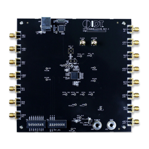
RTKA223021DE0000BU Evaluation Board Manual
1. Functional Description
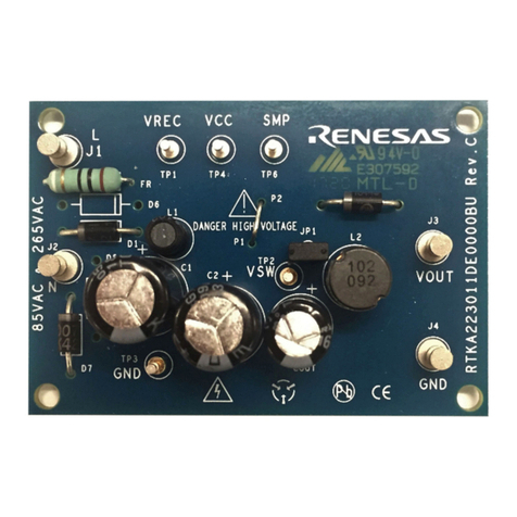
The RTKA223021DE0000BU is a buck regulator implemented with a high-side float-switching topology, with
switching frequency up to 43kHz. D1 is a full bridge rectifier on the input end. FR is a 1A fuse providing input
overcurrent protection. As an option, you can replace the standard fuse with a fusible resistor instead to limit
inrush current.
C1, L1, and C2 consist of the input filter that provides the energy buffer after rectification and reduces conducted
EMI noises to the input. L2, D2, and COUT are the buck converter components. RFB1, RFB2, CFB2, and CFB1
provide the output feedback signal to the IC. D4 and R2 provide VCC biasing current after startup to increase the
efficiency. They can be optional for low-cost low power applications. CVCC is the IC supply capacitor.
1.1 Recommended Equipment and Operating Range
▪AC Power supply capable of generating AC voltage from 85VAC to 265VAC at 60Hz/50Hz, with at least 100mA
output current capability.
▪Load resistor box with adjustable value of 18Ωand up, or an electronics load that can emulate a resistor load or
current load up to 667mA.
▪Multi-meters to measure the output voltage and current.
▪Power meter to measure the AC input power.
1.2 Setup and Configuration
1. Program the AC power supply with a voltage between 85VAC and 265VAC at the corresponding frequency of
60Hz or 50Hz.
2. While the AC power supply is off, connect the output cables of the AC power supply to the L and N terminal of
the RTKA223021DE0000BU. An optional power meter can be added in between the AC power supply output
and the input of the board.
3. Connect the load to the output terminals VOUT and GND.
4. Connect a voltage meter to VOUT and GND and connect a current meter between board outputs and the load.
5. Turn on the AC power supply.
Figure 2. Proper Probe Setup to Measure Output Ripple
