Renogy MT-150 User manual

0
MT-150
RENOGY 150A Peak
High Precision Watt Meter and Power Analyzer
2775 E. Philadelphia St., Ontario CA 91761
1-800-330-8678
Version: 1.1

1
Important Safety Instructions
Please save these instructions.
This manual contains important safety, installation, and operating instructions for the meter. The
following symbols are used throughout the manual to indicate potentially dangerous conditions or
important safety information.
WARNING: Indicates a potentially dangerous condition. Use extreme caution when
performing this task.
CAUTION: Indicates a critical procedure for safe and proper operation of the controller
NOTE: Indicates a procedure or function that is important to the safe and proper operation
of the controller.
General Safety Information
Read all of the instructions and cautions in the manual before beginning the installation.
There are no serviceable partsfor this controller. Do NOT disassemble or attempt to repair
the meter.
Do NOT allow water to enter the controller.
Make sure all connections going into and from the meter are tight.
Battery Safety
NEVER short a rechargeable battery or the meter connected to a rechargeable battery. It
can supply high currents and cause fire explosions. Do NOT let the positive (+) and
negative (-) terminals of the battery touch each other.
Ensure wiring and connections are rated to handle the input/out current and are properly
assembled for each application
Carefully read battery manuals before operation.
Do NOT let the positive (+) and negative (-) terminals of the battery touch each other.
Recycle battery when it is replaced.

2
Table of Contents
General Information......................................................................................................3
Optional Component.....................................................................................................3
Identification of Parts....................................................................................................4
Installation .....................................................................................................................4
Operation.......................................................................................................................5
Measurement Screen Glossary....................................................................................6
Using Auxiliary Power ..................................................................................................7
System Status Troubleshooting ..................................................................................9
Dimensions..................................................................................................................10

3
General Information
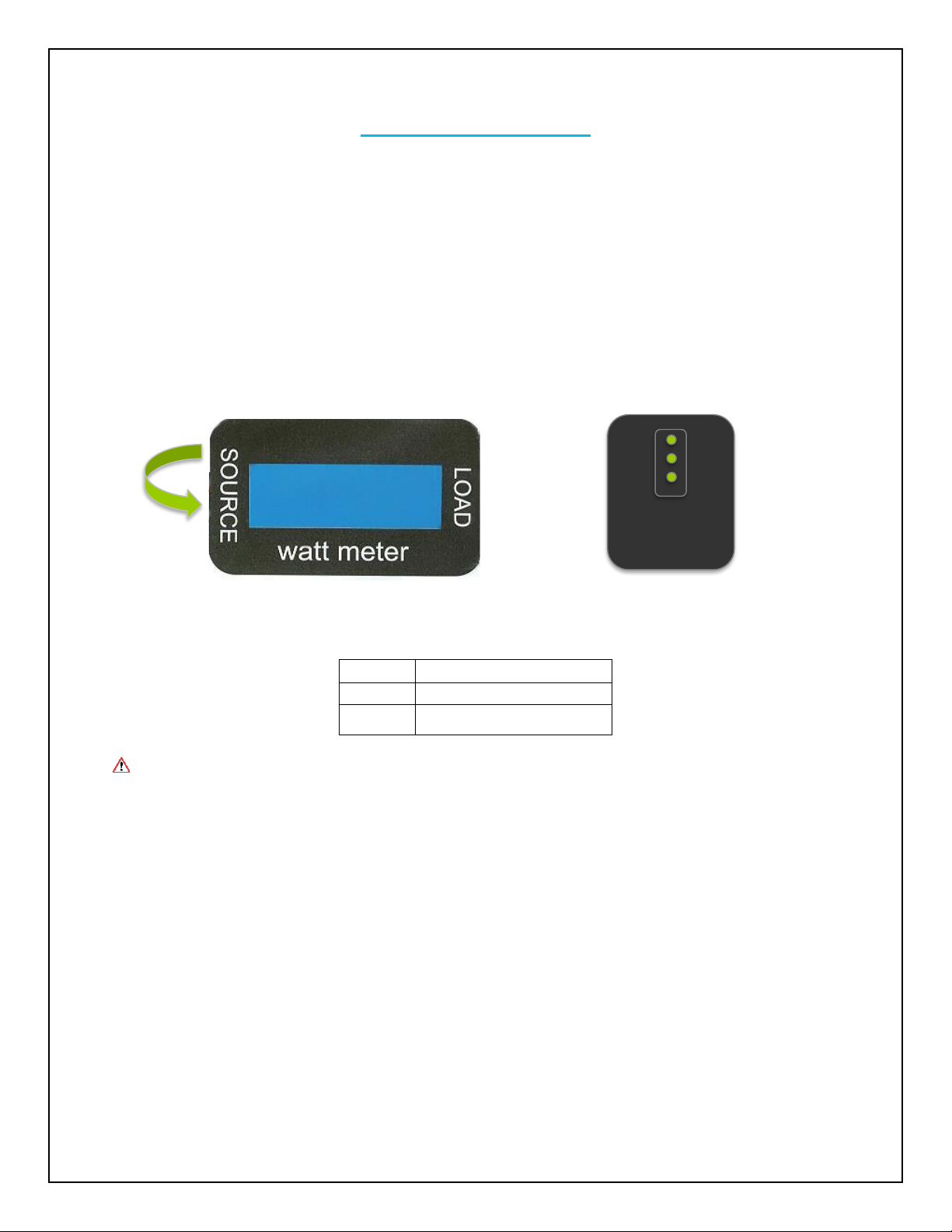
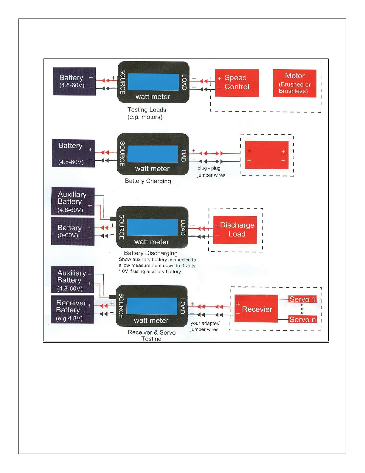
The Renogy 150A High Precision Watt Meter and Power Analyzer is specifically designed for
monitoring solar performance. This easy to use meter can monitor eight electrical parameters that
are essentialto power safety and performance. Theyinclude: amps, volts, watts, amp-hours, watt-
hours, peak amps, minimum volts, and peak watts. With a 60 volt and 150A peak capacity, high
contrast blue display screen, and auto set features, you will surely find many great uses for this
watt meter and power analyzer.
Key Features
Backlit LCD display
Measures energy (Wh), charge (Ah), power (W), current (A), and voltage (V)
Rugged design—Handles 50A continuous and 150A peak at 60V.
Extremely low power consumption, practically ineffective to model’s performance
Precise and accurate readings
Lightweight with many installation possibilities
Features port connector for optional battery for measurement down to 0 volts
Bare wire ends to allow the user freedom for their own type of connections
Optional Component
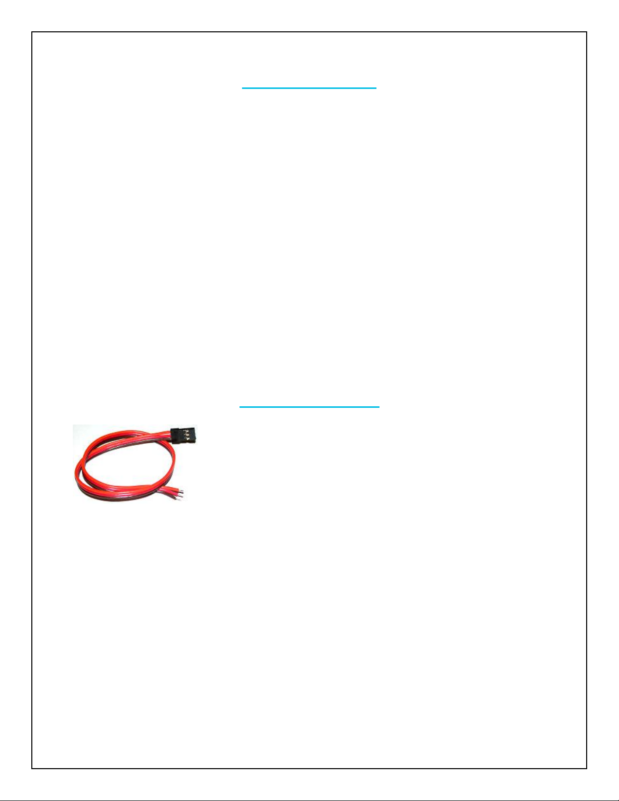
Auxiliary Power Connector Cable
This cable allows the Renogy Watt Meter to connect to an optional
power source, such as a battery pack or a power supply. It has 3 bare
tinned leads for universal application. The main functionality allows
the users to measure down to 0 Volts. The cable is not required, but
very handy for many applications.
NOTE: Although the cable is an accessory to our product, it is not required. Also, Renogy
currently does not carry this accessory and users will need to find their own means on
attaining this cable.

4
Identification of Parts
Key Parts
1. Source Side Connection
2. Load Side Connection
3. Negative Wire
4. Positive Wire
5. Auxiliary Battery Port (Optional Component)
Installation
WARNING: Poor connections and reckless wiring can have serious consequences
including personal injury, electrical shock, and may cause a fire.
CAUTION: Make sure connections are secure and expose no wire that may short.
NOTE: The user is responsible for attaching connectors that are rated to handle the
expected voltage and current limitations.
1. Connect the Positive (+) and Negative (-) leads of SOURCE to the battery or other device’s
terminals.
2. Connect the Positive (+) and Negative (-) leads of LOAD terminals to a device to complete
the circuit.
5
1
2
3
4

5
Operation
WARNING: High power electrical systems pose dangers for independent devices and
meters connected inline. The user should take extra precautions when working with these
devices and take any necessary action to ensure safe use. Shorting a battery with the
meter connected can supply huge currents and have serious consequences including:
explosions, causing fires, damage to equipment, and even personal injury. Make sure your
system does not exceed the values rated on the Renogy 150A Tracer Meter
Once the circuit is complete, the watt meter will turn on, display the default screen, then cycle
through the remaining displays. You can think of the Watt Meter as a set of jumper cables;
essentially a direct connection between same colored SOURCE and LOAD wires. Both the
SOURCE and LOAD leads are electrically “hot” when a battery is connected to wither side.
Current flows from SOURCE to LOAD, assure that all connections are secure to prevent
component damage.
Example #1:
Battery on SOURCE side, Motor Speed Controller (ESC) and motor on LOAD side, With
the ESC on, the watt meter displays the current into the motor, voltage and power at the
battery and the accumulation of Ah and Wh while the motor is running.
Example #2:
Solar Panel on SOURCE side and a battery pack on the LOAD side. The Watt meter
demonstrates the charging current into the battery, the voltage and charging power at
the battery, and the accumulation of the charge in Ah and Wh.
Startup Screen
Displays the peak and minimum measurements
recorded followed by the Amp-Hours (Ah) and Watt-
Hours (Wh) being reset to 0.
Measurement Screen
Displays Amps, Volts, and Watts. Screens are
updated every 0.4 seconds and they are presented
sequentially every 2 seconds in their appropriate units
(Ah, Wh, Ap, Vm, Wp).
100.00A 10.00V
Data Queue 100.0W
100.00A 10.00V
Data Queue 100.0W

6
Measurement Screen Glossary
Parameter
Description
Amps, A & Ap (Current)
Only the current from SOURCE to LOAD is measured. The Amp
value displayed is the average current over the last screen update
interval Peak Amp value (Ap) display is the maximum current drawn
from the LOAD side. Peaks lasting only a fraction of a second can
be captured. Supplying the auxiliary power with a voltage greater
than what the meter it is measuring removes the meter’s operation
current from measurements. To reduce heating, measure currents
over 65 amps from reduced time and consider using connector
which can handle large current.
Volts, V & Vm (Voltage)
The displayed value is the average voltage over the last screen
update interval. The displayed minimum volts value (vm) is the
Minimum voltage (or “sag”) measured on the SOURCE side. The
volts value is measured on the SOURCE side.
Watt-Hours, Wh
(Energy)
The displayed value is the total energy delivered in watt-hours and
it is measured on the LOAD side. For best results, do not interrupt
the SOURCE connection to the watt meter during a charge
measurement.
Amp-Hours, Ah
(Charge)
The displayed value is the total charge in Amp-hours(x1000=mAh)
delivered since the startup screen and it is measured on the LOAD
side. For accurate results, do not interrupt the SOURCE connection
to the watt meter during a charge measurement.
Watts, W & Wp (Power)
The displayed value is the average power delivered in watts (=Volts
x Amps) over the last screen update interval. The displayed peak
watts value (Wp) is the maximum power drawn on the LOAD side
since the startup screen ended. Watts are measured on the LOAD
side

7
Using Auxiliary Power
The MT-150 allows users to connect a battery (pack) or other power source into the 3-pin
connector on the SOURCE side. This power source needs to be at least 4.8V and would allow
the meter to measure down to 0V. The 3-pin connector will accept a Futaba J Connector J
Type, JR, or HiTec type servo plug connector.
NOTE: When using auxiliary power, the user may note some small values presented in the
screen. This is normal behavior and will not affect performance when making real
measurements.
On the side of the SOURCE side, the user will note the 3-pin input by which an auxiliary battery
can be connected. For this particular model, the useful pins will be Pin 1 and Pin 2.
From top to bottom:
Pin 1
Positive (> 4.8V)
Pin 2
Negative (> 4.8V)
Pin 3
Reset (Future model)
WARNING: Never short leads on either side while the power meter is connected to a
power source on either side.

8
The following chart demonstrates different uses with the MT-150

9
System Status Troubleshooting
Meter not turning on
Make sure the connections are properly secured onto the LOAD and SOURCE side of
the meter. If so, disconnect all connections and connect again to resume proper
operation.
Display is dim
Might be due to low voltage. Check to make sure your battery or auxiliary battery have at
least 4.8V connected to the SOURCE side.
Wiring is warm
It is normal for the MT-150 to get warm during high currents. You can cool it with a small
fan.
CAUTION: Make sure connections are secure and expose no wire that may short. Also
make sure operation does not exceed rated technical specifications.
Technical Specifications
Description
Parameter
Operation Voltage:
7 - 55V
Operation Amperage
50A Max; 150A Peak (surge)
Auxiliary Battery Operating Voltage
0 –60 V
Measurement Resolution:
0 –150A, 0.01 A Resolution
0 –60 V, 0.01 V Resolution
0 –9000 W, 0.1 W Resolution
0 –65 Ah, 0.001 Ah Resolution
0 –9000 Wh, 0.1 Wh Resolution
LCD Display
62 x 12.5 mm (2.44 x 0.49 in)
Dimensions:
85 x 45 x 25 mm (3.35x1.77x0.98 in)
Weight
82 g (0.18lbs)
Wire Size
12 AWG

10
Dimensions
NOTE: Dimensions are in inches.
Table of contents
Other Renogy Measuring Instrument manuals

Renogy
Renogy RMS-PGH User manual

Renogy
Renogy Monitoring Screen User manual

Renogy
Renogy MT-50 User manual

Renogy
Renogy ONE Core User manual

Renogy
Renogy Battery Monitor User manual

Renogy
Renogy ONE M1 User manual

Renogy
Renogy RMS-DCDC-US User manual

Renogy
Renogy MT-1 User manual

Renogy
Renogy ONE Core User manual

Renogy
Renogy RMS-RVRE User manual