Rev Electrix Cellpro 10XP User manual

Cellpro 10XP Charger
User’s Guide
© Copyright 2011, 2014 FMA, Inc.
Updated 09/02/2014

2
Table of Contents
Table of Contents..................................................................................................................... 2
Description............................................................................................................................... 3
Features.................................................................................................................................... 3
Precautions.............................................................................................................................. 5
Parts.......................................................................................................................................... 5
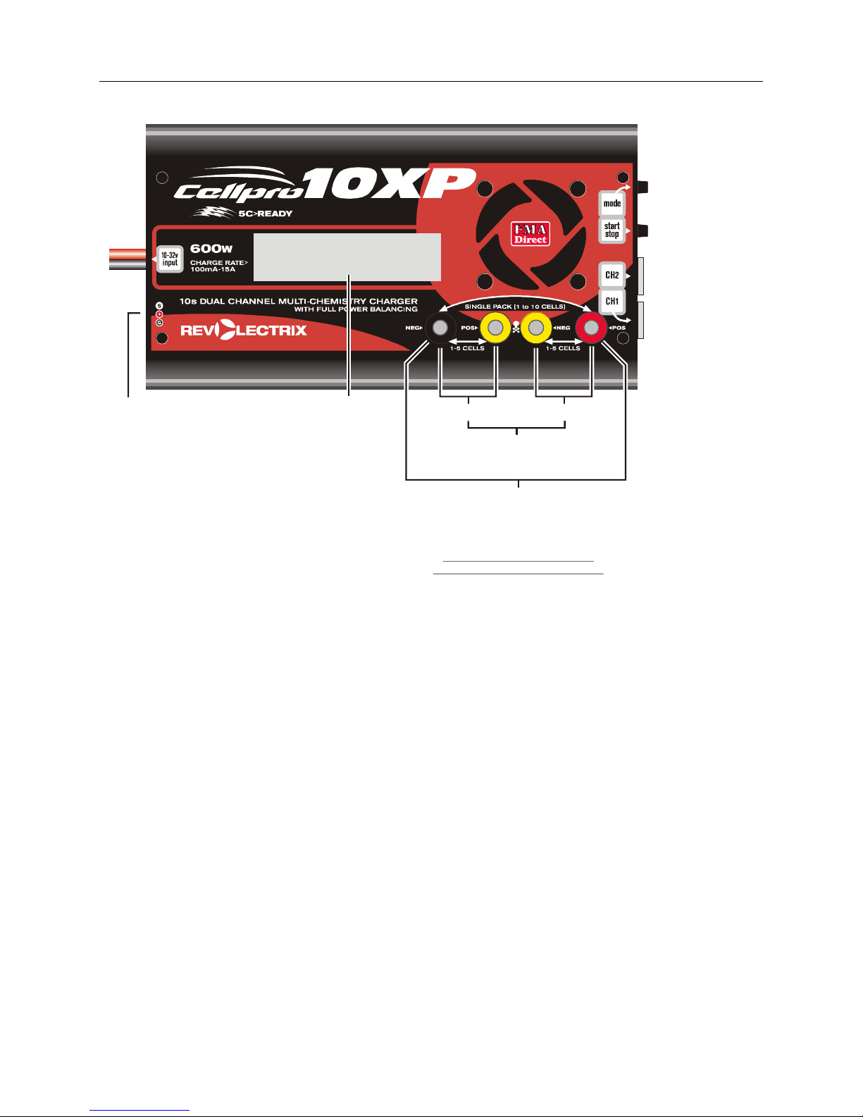
Charger terminology................................................................................................................ 6
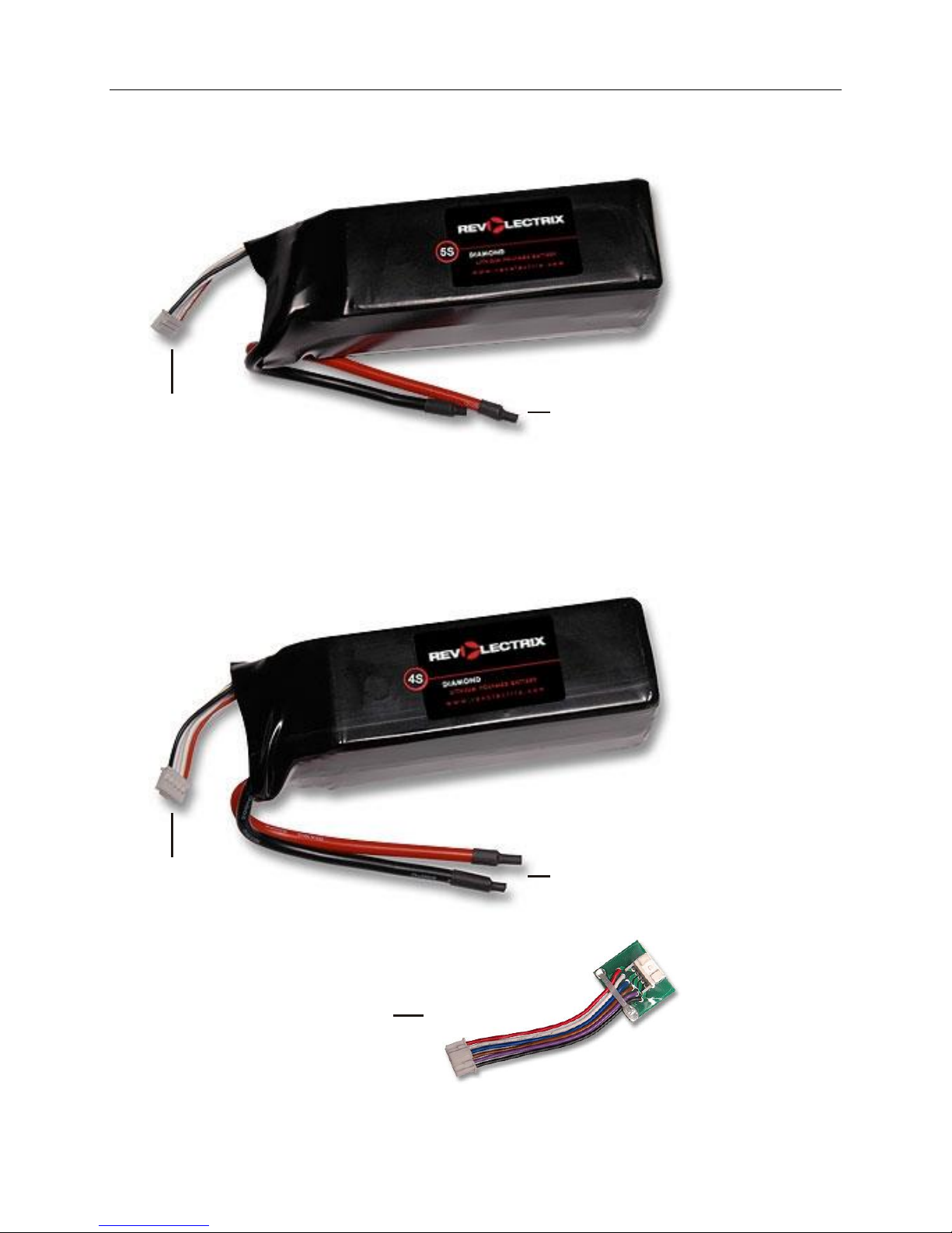
Pack terminology and configurations .................................................................................... 7
REVOLECTRIX Cellpro branded 5s battery packs...................................................................................7
REVOLECTRIX Cellpro branded 2s, 3s, and 4s battery packs................................................................7
REVOLECTRIX Cellpro branded 6s-9s battery packs..............................................................................8
Understanding the Cellpro 10XP Charger.............................................................................. 9
Auto Charging vs. Manual Current Settings..............................................................................................9
Power and Charging Speed......................................................................................................................9
About Factory Presets............................................................................................................................. 11
Power Management Feature...................................................................................................................11
Connecting packs to the charger...........................................................................................12
General information.................................................................................................................................12
Connecting non-Cellpro packs................................................................................................................12
Connecting one 1s to 10s REVOLECTRIX Cellpro pack ......................................................................13
Connecting two 1s to 5s Cellpro packs.................................................................................................13
Applying power to the charger...............................................................................................15
Introduction to presets.............................................................................................................................15
Operating the charger.............................................................................................................16
Overview of button operations: ...............................................................................................................16
Performing Common Tasks:...................................................................................................17
Selecting a preset ...................................................................................................................................17
Changing a preset...................................................................................................................................17
Charging a pack or packs .......................................................................................................................19
Options Menu Explained.........................................................................................................................20
Alternate charging modes.......................................................................................................................23
Using the Charge Control Software.......................................................................................24
Installing the Charge Control Software ...................................................................................................24
Launching the Charge Control Software.................................................................................................24
Connecting the charger to your computer...............................................................................................24
Monitoring charging operations...............................................................................................................24
Limiting charger input current .................................................................................................................25
Defining presets ......................................................................................................................................25
Setting charger options...........................................................................................................................26
Recording charge data............................................................................................................................26
Updating charger firmware......................................................................................................................27
Balance connector wiring.......................................................................................................28
When using FMAWIRING mode (Factory Default Setting)....................................................................28
When using XH/EH WIRING mode.........................................................................................................30
Estimating performance factors ............................................................................................32
Collect data .............................................................................................................................................32
Calculate performance factors................................................................................................................32
Evaluate results.......................................................................................................................................32
Specifications..........................................................................................................................33
Quick start for the Cellpro 10XP Charger..............................................................................34
Troubleshooting......................................................................................................................35
Support options......................................................................................................................37
REVOLECTRIX limited warranty ............................................................................................38

3
Description
Model LC10S15ADC-MC, for use with LiPo, Li-Ion, A123, NiCd, NiMH, and Pb battery packs
10s Multi-Chemistry, 15 Amp, 600W model for automatic and manual charging with available high-power
balancing, overcharge protection, and automatic charge/discharge to storage (for Li batteries)
Features
Charges Lithium Polymer, Lithium Ion, A123, NiCd, NiMH, and Pb packs. Charges any brand of
pack.
Supports high-power balance charging of Li or A123 battery packs. Balance charges one 1s to 10s
pack, or two 1s to 5s LiPo packs simultaneously. When two packs are connected, the balance
connections and pack main discharge wires are wired in series by the charger.
Equipped with Cellpro brand (JST PA series times two, 6 position) balance connectors which enable
the charger to monitor and independently charge each cell to its optimum level (balance charge
operation).
Accepts Cellpro 10s Adapters for plug-and-play compatibility. Cellpro 10s Adapters support from 2s
to 6s battery packs (all brands). For more information on REVO adapters, visit
http://www.revolectrix.com/cellpro_adapters.htm
Backward-compatibility with older Cellpro 4s adapters is assured using the available 6-pin to 5-pin
adapter(s) (REVO PN: CP10S-5S/4S-ADP-US) for charging 2s to 4s Cellpro packs having 5-pin
balance connectors.
Also supports customer-selectable, XH mode. JST XH/EH balance connectors and wiring are
growing to be the dominant scheme in the industry. Switching to XH mode, the CP10XP can support
existing XH style adapters you may already own. Splice in REVO PN: CPBP6P-10-US battery
pigtails to the wires on existing adapters and you are good to go!
Supports non-balanced charge of Li (up to 2s), Ni (up to 28 cells), Pb (up to 24V), A123 (up to 12s).
Accepts 10-32 VDC input.
Up to 15A max charge current.
Maximum 25A input current
720W max continuous input and 605W max continuous output at 30V DC input. Charger will achieve
rated output to a 10s LiPo using 30V DC input. Increasing input voltage beyond 30V does increase
power output, but only if the charger’s output voltage exceeds 42V; e.g., when charging 12s non-
balanced A123 packs. However, 32V DC input is a maximum rating. It is recommended to utilize
input voltage slightly below the absolute maximum.
Supports AUTO rate charging (1.0C, 2.0C, and 3.0C charge rate) using Advanced Fuel Gauging
technology, or manual set currents of 0.10A –15A in 0.10A increments.
Industry’s largest 1A proportional integrated balancers
Power-balance-charge packs through balance connectors in tandem with the main discharge wires of
the battery pack(s). Unit does not support balance-connector only charging.
Compensates for balance wire lengths up to six feet with 1mV accuracy.
Displays individual cell internal resistance to 0.1milliohm, for estimating pack quality, health, and
performance.
Storage Preset available to charge or discharge Li batteries to appropriate per-cell storage levels; 3.8v
(LiPo), 3.0v (A123).

4
During discharge to storage, the CP10XP incorporates 1A-per-cell (nominal) discharge rate using the
charger’s integrated balancing circuitry to provide up to 42W (at 10s) discharge power.
Light-grey, 2 line, 16 character backlit LCD display provides easy readability.
One button, Charge Optimization can be set for an Accurate 1mV cell balance and (C/20 termination)
or for Faster Charging (less balancing accuracy and C/10 termination) using the Charge Control
Software or at the CP10XP interface.
Protects your Pb input source from over-discharge by providing an audible warning when input
voltage of your Pb battery approaches 50% state of charge.
Intelligent controller performs extensive checks to prevent damage to packs and power supply. This
makes it virtually impossible to damage the charger or the batteries from incorrect connections or
wiring; including, but not limited to reverse polarity.
Input reverse-polarity protection.
Simple, effective, 2-button interface allows instant access to presets, preset parameters, and starting
and stopping charger operations.
Access pre-defined, named presets by clicking the MODE button.
Hold the MODE button to access the Main Menu operations: Choose Chg. Amps, Choose Chemistry,
Show Help Screen, Exit. Use the charger’s Main Menu to alter basic settings of presets on-the-fly, or
make the adjustments using the free PC Charge Control Software (CCS).
Press and hold the START/STOP button to start charger operation or cancel/end a charging session.
Press and hold MODE button during power up to access Options Menu; choose input amps limit and
supply low voltage setting (Power Management feature), alternate between FMA or XH balance
wiring schemes, and set quiet charging (no speaker beeps during charging).
Supports Bi-directional, optional PC interface (REVO PN: FUIM2-US or FUIM3-US) which enables
extensive charger setup using the CCS. Configure up to 10 custom presets, adjust speaker volume,
set LCD contrast and control many other settings.
CCS automatically checks for software and charger firmware updates in the background. Update
charger firmware reliably with the click of your mouse button, and without sending the charger back
to the factory. Keep up-to-date with the latest enhancements and bug fixes.
6 different, available Fuel Gauge lookup tables (fuel tables) may be assigned to independent presets
to match the characteristics of different Li battery chemistries. This feature only available using the
CCS.
Works with a wide range of power supplies, even those not rated for high power. Easily changes
from moderate current bench supply at home to car battery at the field using the Power Management
feature. Set Input supply amps limit and supply low voltage settings using the CCS or at the charger
interface, to prevent damage to your input source.

5
Precautions
Follow all instructions in this manual to assure safe operation.
IMPORTANT: Do not disconnect or connect packs while the charger is charging.
Always watch LiPo packs while they are charging. Never leave LiPo packs unsupervised during
charging.
See additional warning sheets provided with your battery packs.
Follow all guidelines for charging, discharging, handling and storing LiPo cells.
Minor arcing may occur when discharge wires are connected to the charger before charging. This is
normal.
Parts
Cellpro 10XP Charger
Removable input plier clips (red/black) for connecting the CP10XP to a DC power source
Optional: FUIM2-US or FUIM3-US PC USB Adapter (required for using the Charge Control
Software)
Optional: Cellpro 6-pin to 5-pin Adapter(s)
Optional: Cellpro 10s Adapters (brands other than REVOLECTRIX Cellpro)
Optional: CP10S-BP12-2PK-US, Cellpro 10s Banana Plug Output Cables (2 pack) –solder the
mating end of the connector you use on your battery’s discharge wires to these cables
Notes:
You may have already received some of the optional items listed above with the purchase of a Combo.
Unless otherwise stated, REVOLECTRIX part numbers found within this manual assume purchase was or
will be made within the United States. If ordering from the International website, drop the “-US” from
the part number.

6
Charger terminology
To DC
Power
Supply
DisplayConnect FUIM2 or FUIM3
PC USB Interface here when
connecting to Charge Control Software
(black wire toward outside wall of case)
Channel 1 Channel 2
Banana jacks for discharge
wires when charging
2 packs at the same time
Use two outer banana jacks for discharge
wires when charging only one pack.
Never connect pack discharge wires
across the two yellow banana jacks.
This will result in blowing the internal fuse.
Note the skull and crossbones
warning between the yellow jacks!
MODE button
START/STOP button
Channel 2
balance connector
Channel 1
balance connector

7
Pack terminology and configurations
REVOLECTRIX Cellpro branded 5s battery packs
Balance connector,
Cellpro brand
(JST PA series)
6 position
Discharge wires:
Red = Pack positive
Blk = Pack negative
5s REVOLECTRIX packs like
the one shown above will connect
directly to the Cellpro 10XP charger
without requiring any additional adapter
REVOLECTRIX Cellpro branded 2s, 3s, and 4s battery packs
Balance connector,
Cellpro brand
(JST PA series)
5 position
Discharge wires:
Red = Pack positive
Blk = Pack negative
2s to 4s REVOLECTRIX packs like
the one shown above require the
5s-to-4s adapter for interconnection
to the Cellpro 10XP charger
(REVO PN: CP10S-5S/4S-ADP-US)

8
REVOLECTRIX Cellpro branded 6s-9s battery packs
Balance connector,
Cellpro brand
(JST PA series)
5 position
Discharge wires:
Red = Pack positive
Blk = Pack negative
6s-9s REVOLECTRIX packs like
the one shown above require the
5s-to-4s adapter for one of the
balance connectors for inter-
connection to the Cellpro 10XP charger
Balance connector,
Cellpro brand
(JST PA series)
6 position
Note: Other brands of batteries will require Cellpro 10XP Adapters. For more information on REVO
adapters, visit http://www.revolectrix.com/cellpro_adapters.htm

9
Understanding the Cellpro 10XP Charger
Auto Charging vs. Manual Current Settings
When balance charging Li batteries, you can set the Cellpro 10XP Charger’s charge rate to one of three
AUTO modes—1.0C, 2.0C or 3.0C—as appropriate for the pack(s) being charged. When one of these
rates is selected, the charger determines the pack’s capacity (over time) and automatically sets the
correct output current using FMA’s advanced Fuel Gauging technology. The accuracy of AUTO
charging depends on how well your battery’s charge curve matches up with the fuel table being used by
the CP10XP. Six different fuel tables are available to support different Li battery chemistries and may
be assigned to individual presets using the Charge Control software. Factory presets for LiPo batteries
are set up for a generic, 15C battery profile. AUTO charging using the default presets may or may not
be accurate for your batteries. The advantage to using AUTO charging is that you do not need to think
about or even know the true capacity of your batteries. You can charge different capacity batteries at
different times without having to adjust the charge rate setting and the charge will automatically adjust
to choose the appropriate charge rate. You just tell the CP10XP how fast you want to charge, and it
does the work for you. For safety reasons, AUTO charging current is capped at 6A, regardless of the
size of the pack being charged. You can also manually set charge current to any value between 0.1A
and 15A in 0.1A increments. Finally, you can select Storage Charge mode which automatically charges
or discharges to the appropriate per-cell storage voltage for LiPo or A123 batteries.
Power and Charging Speed
Cellpro 10XP Charger Power Chart
576
720
768
484
605
645
300
345
393
234
269
306
150
250
350
450
550
650
750
850
+12 +13.8 +15.7 +24 +30 +32
Input Voltage (VDC)
Power (Watts)
Continuous Input (Watts) Continuous Output (Watts)
When one pack is connected to the charger, the pack is initially charged at the selected charge rate (or
the maximum charge rate possible). Using Ohm’s law, the maximum charge rate (Amps) is derived
from the maximum power (Watts) the charger can produce without overheating.
Maximum output power will normally reach approximately 605W when charging a 10s LiPo battery
using a 30V DC input power source, and assuming the input source can deliver a maximum of 720W of

10
clean power to the charger input. Maximum power depends on many factors including pack imbalance
during charge, input (supply) voltage, output (charge) voltage, DC/DC converter efficiency, which
varies between 80% and 95% depending on the relationship of supply voltage-to-charge voltage,
ambient temperature, and internal operating temperature. From the graph, you can see that Increasing
input voltage beyond 30V does increase power output, but only if the charger’s output voltage exceeds
42V; e.g., when charging 12s non-balanced A123 packs. However, 32V DC input is a maximum rating.
It is recommended to utilize input voltage slightly below the absolute maximum.
When the pack reaches about 95% capacity, the charger enters balance charge mode. Charge current
tapers off, but will remain at 1A or higher until the pack voltage slows the current to 1/20th C (Constant
Voltage Mode). When the pack reaches 99% capacity, the charger beeps three times. The pack can be
removed to use, or allowed to continue charging until it is 100% full and the charger displays “Charge
Complete.”
During the entire charge process, the charger power balances the pack using 1A current until all cell
voltages are within 1mV of each other. Power balancing is the process of beginning the balancing
process early in the charge cycle using high-current shunts to drain excess cell voltage while other cells
in the pack have a chance to catch up. Power balancing means the pack tops off faster and the total
charge time is greatly reduced. This is possible because the balance circuitry is internal to the charger.
Automatic temperature control and an integral fan ensure the charger never exceeds maximum safe
operating temperature under any conditions. The result is faster, safer charging.
When charging two packs, the packs are connected in series (the balance connections as well as the
main charge wires). In effect, the charger treats the two packs as a single pack. For example, if you
connect a 3s pack and a 4s pack, the charger operates on them as one 7s pack. If the pack capacities are
different for the two packs connected, the charge rate should be selected based on the lower capacity
pack. Initially, the packs are charged at the selected charge rate (or the maximum charge rate possible)
until one pack becomes fully charged—however, the charger can handle cell balancing of the two packs
completely independently. The second pack continues to charge at a minimum 1A rate until it is full
and balanced.
Notice that one of the packs in a simultaneously-charged pair is always topped off at a minimum rate of
1A (dictated by the maximum balance current available). If the packs have the same capacity, and were
discharged to about the same level, both packs will charge in less than 30 minutes at 3C. However, if
the packs have different capacities, or were discharged to different levels, charging for the pair could take
longer than expected. Since the charger supports a high power balance current of 1A, all other things
being equal, the charger still outperforms competing brands. In most instances, by the time the first pack
is fully charged, the second pack is already approaching constant voltage charge mode; the battery pack
itself is the limiting factor in charge time, not the charger.
Example 1: You are powering an aircraft with two 4s 2100mAh packs connected in series.
Because those packs have the same capacity, and were discharged to about the same level
during flight, you can expect them to charge in about the same time. It would be appropriate
to charge them simultaneously using the Cellpro 10XP Charger.
Example 2: You are powering one aircraft with a 3s 500mAh pack, and other aircraft with a
5s 5000mAh pack. If you charge these packs simultaneously using the Cellpro 10XP Charger,
it would probably take a long time (the 500mAh pack would become full first, then the
charger would switch to its 1A balancing rate to fill up the 5000mAh pack, which could take
several hours). In this case, it would be faster to charge these packs separately because the
charger can then apply optimum (and substantially different) charge currents to each pack.
In some cases, such as Example 2, it will be faster to charge two packs separately rather than
simultaneously. It’s up to you to decide, based on what you know about their respective capacities and
discharge states.

11
In Example 2 above, when the 500 mAh pack reaches 99% capacity (the charger beeps three times), it is
a simple matter to remove the pack from the charger and continue charging the 5000 mAh pack at a
higher charge rate. Here’s how:
1. Connect both packs and start charging them using an AUTO or manual rate setting.
2. Watch the fuel level display. When one pack reaches 99% fuel level, stop charging.
3. Disconnect the full pack.
4. If the partially charged pack is connected to Channel 2, move it to Channel 1.
5. Continue charging the partially-charged pack.
About Factory Presets
During all phases of the charge process, the charger will balance all the cells in Channel 1 and Channel 2
together as one big pack, and report the fuel level of two packs being charged as one big pack. The
exception to this is if you use one of the Factory presets (or set up a custom preset) containing the words
“Dual Channels”. In this case, the CP10XP will balance all the cells in Channel 1 against each other and
all the cells in Channel 2 against each other, and report the fuel level of the two packs independently.
Power Management Feature
The charger will draw up to 25A to deliver its 15A maximum output current. The high input current is
required when the input voltage must be boosted to drive packs having larger numbers of cells in series.
Output power is determined by several factors, including battery pack imbalance during charge, input
voltage, input current, output voltage, ambient temperature, and the charger’s internal temperature.
The charger’s DC-to-DC converter is typically 80% to 95% efficient. Highest efficiency occurs when
the input voltage is higher than the output voltage needed to charge the connected pack(s). However,
the charger cannot tolerate input higher than 32V DC. Supplying input voltage of 30V provides the
highest efficiency, coolest operating temperature and fastest charging times, especially when charging
packs containing more than five cells in series.
You can also manually limit the charger’s input current and adjust the supply low voltage limit so the
charger will not draw more power than the supply can provide. If you know your power supply is rated
for 3A output, for example, you can limit the charger’s input current to 3A. (Be aware that limiting
charger input current may increase pack charge times.) If you are using a Pb battery to power the
CP10XP and you do not want to discharge below a certain voltage, you can set it where you want it.
When the charger is powered from a high current source (such as a car battery), you can adjust the
current limiting to provide maximum pack charging current. Details for changing these settings are
provided in sections “Options Menu Explained” as well as “Limiting charger input current” under
“Using the Charge Control Software”. The Factory Default settings for the Power Management feature
are as follows:
1. Input Supply Current Limit: 25A
2. Input Supply Low Voltage Limit: 11V

12
Connecting packs to the charger
General information
When balance charging, both a balance connector and the main discharge wires must be connected to
the Cellpro 10XP.
When performing a non-balance charge on a 2s Li, A123, NiCd, NiMH, or Pb pack, connect only the
pack’s main discharge wires to the two outer banana jacks on the charger’s front panel.
When charging only one pack, always plug that pack’s balance connector into the charger’s Channel
1 balance port and always connect the main discharge wires to the charger’s outermost banana jacks.
When charging two packs simultaneously, make sure to correlate each pack’s balance connector and
pack discharge leads to the same charger Channel. For example, first pack’s balance connector in
Channel 1 balance port, first pack’s discharge leads to Channel 1 banana jacks (the left two jacks).
Second pack’s balance connector in Channel 2 balance port, second pack’s discharge leads to
Channel 2 banana jacks (the right two jacks).
When charging two packs, both packs must have the same chemistry. For example, you can’t charge
one A123 pack and one LiPo pack at the same time. Never mix chemistries under any circumstances.
After a charge is initiated, never alter the connections between the charger and the battery packs.
Always end the current charge session before making any connection changes. See page 21 for more
information about STARTING and STOPPING charge sessions.
WARNING: Failure to comply with the above could result in fire and/or damage not covered by warranty!
Pack discharge wires are usually not terminated in banana plugs (e.g., they might be terminated in a
Deans connector). For convenience in connecting to the charger, prepare an adapter cable with
banana plugs on the charger end and a connector that mates with the pack’s discharge connector on
the other end. Revolectrix sells banana plugs suitable for this purpose as REVO PN: CP10S-BP12-
2PK-US, Cellpro 10s Banana Plug Output Cables (2 pack).
CAUTION: When using the banana plug adapter cables described above, ALWAYS insert the banana
plugs into the charger BEFORE connecting the adapter cable to the pack. Reverse the sequence when
disconnecting the pack. This will prevent the live banana plugs from touching each other, which would
create a dangerous condition and could seriously damage the pack.
Connecting non-Cellpro packs
Generally, follow the instructions in “Connecting one 1s to 10s Cellpro pack” and “Connecting two 1s
to 5s Cellpro packs” below, but your packs may not be equipped with compatible balance connectors.
REVOLECTRIX offers plug-and-play adapters for charging LiPo packs equipped with balance
connectors made by other manufacturers. Check http://www.revolectrix.com/cellpro_adapters.htm for
adapter compatibility. The Cellpro 10XP Charger works with all existing Cellpro 4s charger adapters.
You must connect a 6-pin to 5-pin Adapter (REVO PN: CP10S-5S/4S-ADP-US) between the charger
and the Cellpro 4s charger adapter, as shown here:
If an adapter isn’t available for the pack you want to charge, or if the pack doesn’t have a balance
connector, the REVOLEXTRIX PN CPBP7-US (Cellpro battery pigtail 10”, 5 position) and/or PN
CPBP6P-10 (Cellpro battery pigtail 10”, 6 position) cable assemblies can be used to make the pack
compatible with the Cellpro 10XP Charger. Instructions for connecting these cable assemblies to your
packs are provided in the “Cellpro Pin Lead Connection” document at:
http://www.revolectrix.com/support_docs/item_1315.pdf
Note: see also “Balance connector wiring” later in this manual.

13
Connecting one 1s to 10s REVOLECTRIX Cellpro pack
1. How you connect the Cellpro pack’s balance connector(s) to the charger depends on the pack’s
configuration. Use the photos in the section “Pack terminology and configurations” above, then find
the configurations in the diagrams below and connect as shown in that diagram.
2. When charging a single pack, plug the discharge wires into the outermost banana jacks.
Connecting two 1s to 5s Cellpro packs
1. How you connect the Cellpro packs’ balance connectors to the charger depends on the packs’
configurations. Use the photos in the section “Pack terminology and configurations” above, then find
the configurations in the diagrams below and connect as shown in that diagram.

14
2. When charging two packs simultaneously, connect the discharge wires into the banana jacks as shown
below.

15
Applying power to the charger
To apply power to the charger: Connect the charger to a 10V to 32V DC power supply, field battery
or car battery. If your bench power supply is equipped with banana jacks for output, you can remove
the plier clips from the charger’s input cables and plug the cables directly into the power supply jacks.
When the charger is powered up, it displays the following “Welcome” screen:
Cellpro 10XP
[firmware version]*
Press the MODE button one time to advance to the “Preset Menu”
Preset 1
[chem] [BAL] @ [charge current]*
Press the MODE button repeatedly to scroll through and view/select the Cellpro 10XP’s 10 presets,
one at a time.
*Information in square brackets varies.
Introduction to presets
As shipped from the factory, the charger has ten presets. The presets are displayed in the “Preset Menu”
and display in the charger’s LCD as follows:
Preset Name/Settings
Description
Preset 1
LiPo BAL @ 1.0C
Designed for a single 1s-10s LiPo battery, balance
charged at AUTO 1.0C.
P2 Dual Channels
LiPo BAL @ 1.0C
Designed for two, 1s-5s LiPo batteries, balance
charged at AUTO 1.0C.
Preset 3
LiPo BAL @ STORE
Designed to automatically storage charge or discharge
LiPo batteries to 3.8v per cell for safe storage.
Preset will charge using AUTO 1.0C or discharge using
1A internal balance circuits.
Preset 4
LiPo 2sU @ 1.0A
Designed for one 2s LiPo, unbalance charged at 1.0A
manual rate setting.
Preset 5
A123 BAL @ 4.6A
Designed for 1s-10s A123 battery, balance charged at
4.6A manual rate setting.
P6 Dual Channels
A123 BAL @ 4.6A
Designed for two, 1s-5s A123 batteries, balance
charged at 4.6A manual rate setting.
Preset 7
A123 2sU @ 4.6A
Designed for one 2s A123, unbalance charged at 4.6A
manual rate setting.
Preset 8
NiCd 8mV @ 1.0A
Designed for 1-26 cell NiCd, non balance charged, peak
detection, 8mV fallback at 1.0A manual rate setting.
Preset 9
NiMH 5mV @ 1.0A
Designed for 1-26 cell NiMH, non balance charged, peak
detection, 5mV fallback at 1.0A manual rate setting.
Preset 10
LEAD 12V @ 3.0A
Designed for 12V Lead Acid Battery, non balance
charged at 3.0A manual rate setting.
When power is applied, the charger always initializes to the last preset used for charging. If you altered
the charge settings for a preset at the charger (as described in “Changing a preset,” later in this manual),
those changes are retained when the charger is disconnected from power, and will be reapplied when the
charger is powered up again.

16
“Selecting a preset” and “Changing a preset,” in the next section, provide additional information.
Note: If you programmed the charger using the Charge Control Software, different presets may be
available. Also, if you have been using the software, you may have given the factory presets different
names. Bottom line: if you change settings at the charger, or redefine presets, you probably won’t see the
factory presets shown above. To revert back to the original factory settings above, initiate a Factory
Restore using the CCS, Presets tab.
Operating the charger
You operate the charger using the MODE button and START/STOP button on the right side of the
charger. This simple, effective, 2-button interface allows instant access to presets, preset parameters, as
well as starting and stopping charger operations.
MODE button: enables you to view/select a preset, change preset parameters and display charging
data during charging.
START/STOP button: enables you to start charging after you have selected a preset, and to stop or
cancel a charging session at any time. The START/STOP button also allows you to toggle back and
forth between Accurate and Faster Charge optimizations (applicable to LiPo and A123 battery packs
only).
Overview of button operations:
Following is an overview of all possible functions available using these buttons. These functions are
listed in the approximate order you might use to traverse the CP10XP.
At start up, press the MODE button to access and scroll the Preset Menu and to view/select pre-
defined, named presets and their settings, one at a time. A preset is considered “selected” when its
name and settings are listed on the charger’s LCD.
At any time prior to starting a charge operation, press and hold the MODE button to access the
Main Menu options: Choose Chg. Amps, Choose Chemistry, Show Help Screen, Exit.
While watching the scrolling menu options, continue holding the MODE button, then, release it
only when you see the menu option you want. Now you may use the charger’s menu to alter
parameters of presets on-the-fly. Note: Preset parameters are permanently saved the instant they are
changed.
When inside of Main Menu options, press the MODE button to change preset parameters.
When changes to preset parameters are complete, press and hold the MODE button to access the
Main Menu again. Then choose Exit to return to the Preset Menu.
Press the START/STOP button to toggle back and forth between Accurate vs Faster Charge
optimization. This feature available only when a LiPo or A123 balanced preset is selected.
Press and hold the START/STOP button (for 1 second) to start charger operation or cancel/end a
charging session.
At any time while charge is in progress, press the MODE button to view real-time operating
information and charging data.
Special Button Operation:
Press and hold MODE button while applying power to access and scroll the Options menu: CHOOSE
SPLY AMPS, LOWS SUPPLY VOLTS, NODE CONNECTOR, QUIET CHARGING, Exit. Use the Options
Menu to choose input amps limit and supply low voltage setting (Power Management feature),

17
alternate between FMA or XH balance wiring schemes, and set quiet charging (no speaker beeps
during charging).
Performing Common Tasks:
Selecting a preset
At start up, press the MODE button to access and to scroll the Preset Menu and view/select pre-
defined, named presets and their settings, one at a time.
The preset displayed when you stop pressing the MODE button is the “selected” preset. Once the preset
is selected, you can change the parameters for this preset (see “Changing a preset”) or begin charging by
pressing and holding the START/STOP button (for one second).
Note: The Charge Control Software enables you define up to ten custom presets. Using the CCS, you
can change the names of the Factory Presets, or change any of the available parameters associated with
each preset. If you have defined custom presets, you can—at the charger—select any preset. (If you
have not defined custom presets, the factory presets are available.)
Changing a preset
You can change the charge parameters for the currently selected preset to match the characteristics of
the pack(s) you are charging.
At any time prior to starting a charge operation, press and hold the MODE button to access the
Main Menu options: Choose Chg. Amps, Choose Chemistry, Show Help Screen, Exit.
While watching the scrolling menu options, continue holding the MODE button, then, release it
only when you see the menu option you want. Now you may use the charger’s menu to alter
parameters of presets on-the-fly. Note: Preset parameters are permanently saved the instant they are
changed.
1. Select the preset you want to change (see “Selecting a preset,” above).
2. At this point, there are several things you can do:
To change the charge current:
a. Press and hold the MODE button, then release it when the display changes to this:
Choose Chg. Amps
Hold for More
Note: If you hold the MODE button down longer, you’ll see Choose Chemistry,etc (described
below)
When you release the MODE button, you’ll see the charge current of the selected preset:
Choose Chg. Amps
Charge @ [current]
b. Then:
Press the MODE button about once per second to increase current in 0.1A steps.
Press the MODE button quickly twice to increase current to the next whole Amp.
When the maximum current is reached, press the MODE button once for each of the
following three AUTO charge modes or STORAGE charge mode:

18
1.0C (where C = pack’s capacity)
2.0C
3.0C
STORE (to charge or discharge pack to 50% capacity; optimum for long-term storage)
(Return to manual charge current settings at 0.1A)
Note: The charger’s AUTO charge fuel gauge tables are optimized for Lithium Cobalt batteries. If you are
charging Lithium Manganese batteries, AUTO charge modes may not be accurate. Manual current
settings are recommended when charging Lithium Manganese batteries. Use the CCS to assign the
appropriate fuel gauge table to your presets to improve the accuracy of AUTO charge mode.
To change the chemistry:
a. Press and hold the MODE button, then release it when the display changes to this:
Choose Chemistry
Hold for More
Note: If you hold the MODE button down longer, you’ll see Show Help Screen, etc (described
below).
When you release the MODE button, you’ll see the chemistry setting:
Choose Chemistry
[chemistry] [BAL] [voltage]
b. Press and release the MODE button until you see the chemistry you want. Choices are:
Chemistry/Charge Mode
Description
LiPo BAL 4.20V
LiPo Balance Charge to 4.20V per cell
LiPo BAL 4.22V
LiPo Balance Charge to 4.22V per cell
LiPo BAL 4.10V
LiPo Balance Charge to 4.10V per cell
A123 BAL 3.65V
A123 (or LiFe) Balance Charge to 3.65V per cell
NiCd 8mV Fall Bk
NiCd Unbalance Charge, Peak Detect, 8mV Fallback
NiMH 5mV Fall Bk
NiMH Unbalance Charge, Peak Detect, 5mV Fallback
LEAD 6V
Lead Acid Charge to 6V
LEAD 12V
Lead Acid Charge to 12V
LEAD 18V
Lead Acid Charge to 18V
LEAD 24V
Lead Acid Charge to 24V
LiPo 1sU 4.20V
LiPo Unbalance Charge, 1s to 4.20V
LiPo 2sU 8.40V
LiPo Unbalance Charge, 2s to 8.40V
A123 1sU 3.65V
A123 (or LiFe) Unbalance Charge, 1s to 3.65V
A123 2sU 7.30V
A123 (or LiFe) Unbalance Charge, 2s to 7.30V
A123 3sU 10.95V
A123 (or LiFe) Unbalance Charge, 3s to 10.95V
A123 4sU 14.60V
A123 (or LiFe) Unbalance Charge, 4s to 14.60V
A123 5sU 18.25V
A123 (or LiFe) Unbalance Charge, 5s to 18.25V
A123 6sU 21.90V
A123 (or LiFe) Unbalance Charge, 6s to 21.90V
A123 7sU 25.55V
A123 (or LiFe) Unbalance Charge, 7s to 25.55V
A123 8sU 29.20V
A123 (or LiFe) Unbalance Charge, 8s to 29.20V
A123 9sU 32.85V
A123 (or LiFe) Unbalance Charge, 9s to 32.85V
A123 10sU 36.50V
A123 (or LiFe) Unbalance Charge, 10s to 36.50V
A123 11sU 40.15V
A123 (or LiFe) Unbalance Charge, 11s to 40.15V
A123 12sU 43.80V
A123 (or LiFe) Unbalance Charge, 12s to 43.80V
To get help using the Cellpro 10XP: Press and hold the MODE button, then release it when the
display changes to this:

19
Show Help Screen
Hold for More
Note: If you hold the MODE button down longer, you’ll see Exit,etc (described below)
Press the MODE button repeatedly to scroll the Help Screen information
To Exit the Main Menu and return to the Preset Menu: Press and hold the MODE button, then
release it when the display changes to this:
Exit
Hold for More
Note: You may press and hold the MODE button from any place within the menu to change menu
options or select Exit. Remember, any changes you make while in the Main Menu are saved the instant
you make the changes. If you hold the MODE button down longer, you’ll see the previous Main Menu
options described above.
or
To Quick Start a Charge (Exit the Main Menu and begin charging in one operation if a pack is
connected): Press and hold the START/STOP button for one second. Details are provided in the
next section.
Charging a pack or packs
1. Before charging, pack(s) must be properly connected to the charger. See “Connecting packs to the
charger,” earlier in this manual for details. Also, the correct preset must be selected for the packs
connected to the charger. See “Selecting a preset”, earlier in this manual for details.
2. Press and hold the START/STOP button for one second to enter Charging Mode.
3. You will see the following screens in sequence:
PLEASE WAIT…
CHRGING LiPo BAL
MODE for info.
*above screen will vary depending on what preset is being used
Note: because the CP10XP supports automatic storage charge/discharge to 50%, the initial LCD
indication may show DSCHGING for up to 10 seconds, even if a charge was initiated. This is normal.
4. While in Charge Mode, you can take the following actions:
To view pack and operating data: Press the MODE button repeatedly to cycle through the
following screens. (These examples assume two packs are being charged using one of the Dual
Channel presets; if one pack is being charged, only the top line may appear in some screens.)
C 1.00A 00:00:59
Supply=12.2V/ 3A
Charge current and charge time.
Supply voltage and input current.
[preset name]
[chem] [BAL] @ [charge current]
Selected preset.
Preset’s charging settings.

20
[chemistry] [BAL] [charge process]
[chemistry] [BAL] [charge process]
Chemistry and charge process (Fast
Charging, Balance Charging, etc.) in effect
for each channel.
Ch1 Fuel = 47%
Ch2 Fuel = 55%
Results of unique FMA algorithm that
determines pack “fuel level.” Data is also
used to calculate correct C rate during
1/2/3C charging.
Ch1 Pack = 15.772V
Ch2 Pack = 15.761V
Total pack voltage(s).
Ch1 42mAh In
Ch2 40mAh In
mAh put back into pack(s) during charging.
1:3.956V 2:3.956V
3:3.956V 4:3.956V
Individual cell voltages.* “:” indicates Ch1
screen auto scrolls to show all cells:
5=3.966V 6=3.966V
7=3.966V 8=3.966V
Individual cell voltages.* “=” indicates Ch2
1:12.3mΩ 2:13.2
3:12.1mΩ 4:14.2
Individual cell internal resistances in
milliohms.*† “:” indicates Ch1
screen auto scrolls to show all cells:
5=11.8mΩ 6=13.5
7=12.4mΩ 8=12.6
Individual cell internal resistances in
milliohms.*† “=” indicates Ch2
*Cells are numbered from 1 through n, where 1 is the first cell in the pack connected to Ch1, and n is the last cell in the pack
(if only one pack is being charged) or the last cell in the pack connected to Ch2 (if two packs are being charged).
†For the charger to calculate internal resistances, pack must be at less than 80% fuel level at start. Internal resistances will
be available for display after about 12 minutes of charging, and will be periodically updated after that.
5. Note, when you press and hold the START/STOP button to initiate a charge or storage operation
(step 2 above), you are actually starting a charge “session”. During a session, the data is logged to the
charger’s memory, the LCD, and to the CCS (if connected to the PC). When the charger is allowed to
finish the operation, the LCD will read, e.g., LiPo [BAL] DONE
To end the charge session and clear logged data: Press the START/STOP button for one second.
The charger flashes CHARGER STOPPED then displays the Preset Menu.
Note: Pack data is lost when you end the charge session, so if you want to see it, cycle through the saved
data by pressing the MODE button before pressing and holding the START/STOP button.
To cancel charging at any time: Press and hold the START/STOP button for one second. The
charger flashes CHARGER STOPPED then displays the Preset Menu.
Note: Pack data is lost when you end the charge session, so if you want to see it, cycle through the saved
data by pressing the MODE button before pressing and holding the START/STOP button.
Options Menu Explained
In addition to the charger’s Preset Menu, and Main Menu, there is also an Options Menu available for
altering basic charger settings using the charger’s interface. The Options Menu is accessed by pressing
Table of contents
Popular Batteries Charger manuals by other brands

Hitachi
Hitachi UC 14YFA Technical data and service manual

ClipperCreek
ClipperCreek HCS SERIES installation guide

Extreme Max
Extreme Max Battery Buddy Pro Installation and owner's manual

VOLTCRAFT
VOLTCRAFT V-CHARGE 100 DUO operating instructions

Teac
Teac PD-D2610 Service manual

DEFA
DEFA WorkShopCharger 25A user guide