© 2000 R F Industries Pty Ltd
Doc Ref:INS-36726-2
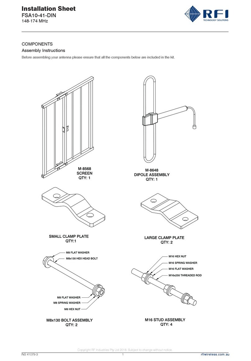
1. Cut end of cable squarely.
2. Remove 35mm of the vinyl jacket and slide the couplin rin onto the cable.
3. Remove 25mm of the braid and fan back as shown (Fi .2).
4. Remove 25mm of the dielectric from the centre conductor takin care not to
dama e the inner conductors (Fi .2).
5. Thread centre conductor of the cable throu h the connector from the back
(Fi .3). When you are sure that all of the strands of the centre conductor are
protrudin from the pin, screw the connector clockwise onto the braid.
6. Continue to screw the body onto the cable until it becomes fairly ti ht (Fi .4).
DO NOT OVERTIGHTEN OR SHORTING OF THE CONNECTOR MAY
RESULT.
7. Trim any excess conductor from the pin. The centre conductor shouldpreferably
be soldered, thou h the UHF-104 can be terminated by ently crimpin the pin.
8. For final assembly screw the couplin rin onto the connector body (Fi .5).
FIG.1
FIG.2
FIG.3
FIG.4
FIG.5
Installing The Coaxial Connector Model UHF-104
MOUNTING INSTRUCTIONS
Figure A
""
""
"Stepped" Nut Use
WHIP-63-71
16.0mm Hole
8.5mm Hole
2
RG58C/U Cable
Male Connector UHF-104
(CD63-71-73U only)
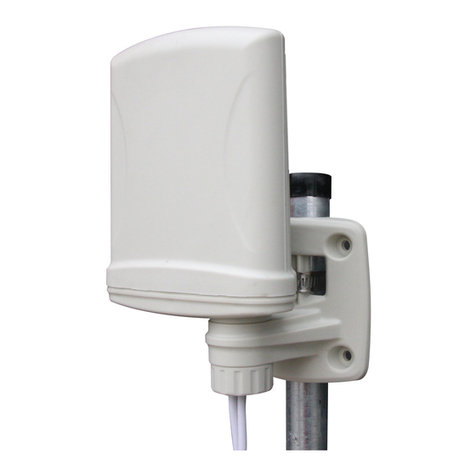
Choosing a mounting position
When choosin a mountin location try to ensure that the
whole antenna, in particular the whip section is as hi h as
possible and as far away as possible from metallic
obstructions (e. . roof racks, or vehicle pillars). When
mounted in a vertical position well removed from such
obstructions the antenna will provide optimum performance.
Installation Procedure
1. Fit the base coil and cable assembly to the mountin
bracket to be used.
NOTE: Fit the hex locknut on the antenna. Using the
stepped nut the antenna can be installed in a 16mm
hole or in erted to allow placement in a 8.5mm hole
(see figure A).
2. Fit the mountin bracket to the vehicle. The preferred
position for utter mounts is near the centre door pillar
on the drivers side.
3. Route the coaxial cable into the vehicle and to the
transceiver via the best and most direct path. NOTE:
Where the cable enters the ehicle try to a oid
positions which will result in excessi e wear or
compression. It is a good idea when using gutter
mounts to use the rear door rather than the front door
for example.
4. Fit the whip section to the base coil.
5. Fit the connector to the coaxial cable and connect to
the tranceiver.
6. Test the VSWR usin an in-line RF power meter.
7.7.
7.7.
7. Do not tune the antenna. This antenna is pre-tuned
and should not require adjustment. If the VSWR is in
excess of 1.5:1, test the coaxial connectors and cables.
NOTE: Due to the design of the high impedance
matching circuit, a DC short will exist between the
braid of the coaxial cable and the radiating element of
the antenna. There should not, howe er be a short
between the outer and centre conductors of the coxial
cable. If there is a short across the coaxial cable, this
would indicate incorrect coaxial connector fitting.
Please seek your dealers ad ice.
Note: Your DEALER can fit new cable to your antenna
quickly and easily. DO NOT attempt this yourself as
SPECIFIC instructions are required.
