7
Excessively long cable connections are not good practice. Try to keep these lines to a minimum to
reduce system voltage drop.
BATTERY (+B) & 0V
These 2 connections are to be connected to the battery.
• Ensure that the battery is connected with the right polarity. Although reverse polarity will
not harm the battery, power supply or the load, no backup of the load will occur during a
power outage.
• Consult battery manufactures data before use with the power supply.
• Excessively long cable connections are not good practice. Try to keep these lines to a
minimum to reduce system voltage drop.
RELAY
The 2 relay connections are the floating alarm relay contacts.
• Connect these pins to any circuit, which is required to be activated by an alarm
condition. The 2 pins become shorted when an alarm condition occurs.
• These pins must not be connected to mains circuits or any other hazardous voltage
circuits.
Cabling
AC Cabling: A cable size of 0.75 mm2 (1 8AWG) is recommended.
DC Cabling: A minimum cable size of 1 .5 mm2 (1 6AWG) is recommended.
Note, maximum size of cable to output connector is 2.5 mm2 or 1 2AWG
DC load cables must be sized to carry the maximum full load current and not exceed the system
volt-drop requirements.
Connection
The requirements for wiring a SME240-1 2-20 into a system are as follows:
LOAD (+L) & 0V
These 2 connections are the DC output of the power supply. These connections are to supply the
load.
• These connections cannot be paralleled with output of duplicate power supply for
increased current output.
• The load connection must not be directly connected to the battery or paralleled with the
battery connection. This will disable the battery low voltage disconnect circuit and defeat
the internal battery fuse.
Voltage Setting
When the PSU is turned on without the battery connected to the battery terminals, the output
voltage may be adjusted within the range specified in table 2.
The output voltage adjustment is achieved in the following way:
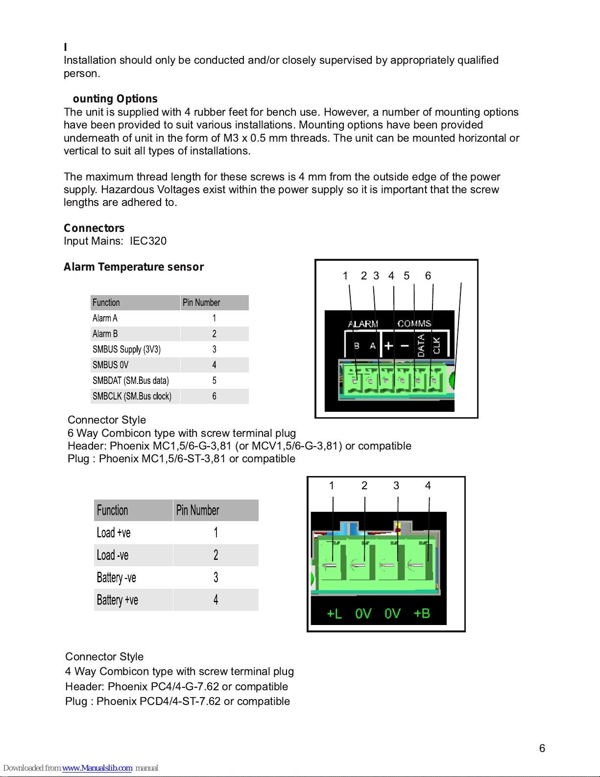
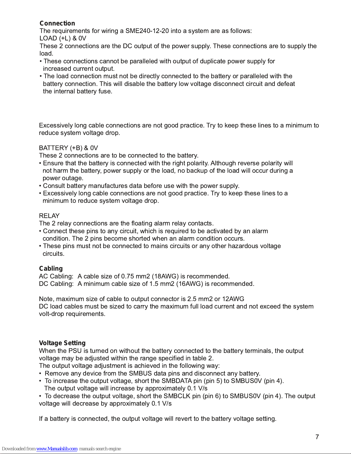
• Remove any device from the SMBUS data pins and disconnect any battery.
• To increase the output voltage, short the SMBDATA pin (pin 5) to SMBUS0V (pin 4).
The output voltage will increase by approximately 0.1 V/s
• To decrease the output voltage, short the SMBCLK pin (pin 6) to SMBUS0V (pin 4). The output
voltage will decrease by approximately 0.1 V/s
If a battery is connected, the output voltage will revert to the battery voltage setting.