RGK Octane Sub4 User manual

User Manual
Octane Sub4 User Manual
UM-OctaneSub4-018-US
EN
WHEELCHAIR
DIRECTIONS FOR USE

User Manual
UM-OctaneSub4-018-US
Octane Sub4 User Manual |
2
Thank you for choosing RGK,
Welcome to the RGK family and we hope the product and
service you have received has exceeded your expectations.
Please take the time to read the instructions and familiarise
yourself with your new wheelchair to ensure you benet from
the maximum safety, performance and longevity.
We want you to be fully satised with our products and services
and we are constantly working to develop our products further.
For this reason, changes can occur within our range of products
with regard to form, technology and equipment. Consequently,
no claims can be construed from the data or pictures contained
in this user manual.
WARNING:
Do not operate this equipment
without rst reading and
understanding this user manual. If
you are unable to understand the
warnings and instructions, contact
RGK or a healthcare professional
(doctor / therapist) before
attempting to use this equipment
- otherwise injury or equipment
damage may result.
As the manufacturer, RGK Wheelchairs
declares that the lightweight
wheelchairs conform to the 93/42/EEC/
2007/47/EEC guideline.
RGK Wheelchairs LTD.
Unit 8 A/B/C Ring Road Zone 2, Burntwood
Industrial Estate, Burntwood, Staordshire,
WS7 3JQ, UK
Call: +44(0)1543 670 077
Email: [email protected]om
Set Up Guide:
1. Carefully remove product and any loose parts from the box and ensure nothing is left in the
packaging.
2. Read contents of this user manual thoroughly and understand the safety risks.
3. Attach the wheels and separate parts.
4. Check everything is as expected and that all parts are secured, functioning and set up
correctly, including tyre pressure.
5. Adjust the upholstery ensuring it provides the right levels of support to suit your posture and
comfort requirements.
6. Adjust the footplate height if required to ensure the correct support for your feet and balance.
7. Once ready and in a safe environment, carefully transfer into your new wheelchair and ensure
it functions correctly.
8. Before going outdoors or on rougher terrain, ensure you have fully tested the wheelchair and
are condent with the balance point and how the chair functions.
9. If you have questions on the set up of your wheelchair, please contact your local authorized
dealer. Happy rolling!

User Manual
UM-OctaneSub4-018-US
Octane Sub4 User Manual |
3
Contents
Contents
4
5
8
9
10
11
12
12
13
13
14
14
15
16
17
18
19
20
21
22
23
Daily Manual Propelled Wheelchair
Safety Summary
Safety Inspection Checklist
Troubleshooting Guide Mechanical
Procedure 1 - Upholstery
Procedure 2 - Rear Wheels
Procedure 3 - Tyres and Inner Tubes
Procedure 4 - Camber Bar
Procedure 5 - Castor Wheels and Forks
Procedure 6 - Wheel Locks
Procedure 7 - Footrest
Procedure 8 - Folding Backrest
Procedure 9 - Push Handles
Procedure 10 - Anti-Tips
Procedure 11 - Sideguards
Transportation
Transportation
Technical Data
Recycling/disposal
Identication/Serial Number
Warranty
CAUTION:
Advice to user that potential damage to equipment
may occur if the advice is not followed.
NOTE:
General advice or best practice
DANGER:
Advice to the user of a potential risk of serious injury
or death if the advice is not followed.
WARNING:
Advice to the user of a Potential Risk of injury if the
advice is not followed.
NOTE:
The wheelchairs shown and described in this user
manual may not correspond in every detail exactly
to your own model. However, all instructions are
completely relevant, regardless of possible detail
dierences. The manufacturer reserves the right to
alter without notice any weights, measurements or
other technical data shown in this manual. All gures,
measurements and capacities shown in this manual
are approximate and do not constitute specications
NOTE:
Please keep a note of your local authorised dealer’s
contact details in the space provided. In the event of a
breakdown, contact them and try and give relevant
details so they can help you quickly.
Denitions

User Manual
UM-OctaneSub4-018-US
Octane Sub4 User Manual |
4
Daily Manual Propelled Wheelchair
A - BACKREST
B- WHEEL LOCKS
C - REAR WHEELS
D - CASTOR WHEELS
E- CASTOR FORKS
F - FOOTPLATE
G- FOOTPLATE COVER
H- CAMBER AXLE
I - FRAME
J - UNDER SEAT BRACE BAR
K - CUSHION & COVER
L - SIDEGUARD
Fig 2.

User Manual
UM-OctaneSub4-018-US
Octane Sub4 User Manual |
5
Safety Summary
Safety Summary
Use
Wheelchairs are exclusively for children and adults who are
unable to walk or have limited mobility, for their own personal
use, when self-propelling and being moved by a third party
(pushed by an attendant), within the home and outdoors.
The maximum weight limit (includes the user and any weight
of accessories tted to the chair) is marked on the serial
number label, which is axed to the camber axle or the under-
seat brace bar.
Warranty can only be considered if the product is used under
the specied conditions and for the intended purposes. The
intended lifetime of the wheelchair is 5 years.
Please do not use or t any third-party components to
the wheelchair unless they are ocially approved by RGK
Wheelchairs.
Area of Application
The variety of tting variants as well as the modular design
mean that it can be used by those who cannot walk or have
limited mobility e.g. due to:
- Paralysis
- Loss of extremity (leg amputation)
- Extremity defect deformity
- Joint contractures / joint injuries
- Illnesses such as heart and circulation deciencies,
disturbance of equilibrium or cachexia as well as for elderly
people who still have the strength in the upper body.
When considering provision, please also note the body size,
weight, physical and psychology constitution, the age of the
person, living conditions and environment.
Final Selection of the type of wheelchair to be used by an
individual rests solely with the user and their health care
professional capable of making such a selection.
General safety
The engineering and construction of this wheelchair has
been designed to provide maximum safety. International
safety standards currently in force have been fullled where
appropriate. Nevertheless, users may put themselves at risk
by improperly using their wheelchairs. For your own safety,
the following rules must be strictly observed.
Unprofessional or erroneous changes or adjustments
increase the risk of accident. As a wheelchair user, you are
also part of the daily trac on streets and pavements, just
like anyone else. We would like to remind you that you are
therefore also subject to any and all trac laws.
Be careful during your rst use in your new wheelchair and
get comfortable and condent before attempting outdoors
or dicult obstacles. It is possible that potholes or uneven
ground could cause this wheelchair to tip over, especially
when riding uphill or downhill. When riding forwards over a
step or up an incline, the body should be leaning forward.
Before each use, the following should be checked:
• Quick release axles on the rear wheels
• Velcro on seats and backrests
• Tyres and tyre pressure
• Wheel locks
Before changing any of the adjustments of the wheelchair,
it is important to read the corresponding section of the user
manual.
WARNING:
CHOKING HAZARD – This mobility aid uses small parts
which under certain circumstances may present a
choking hazard to young children.
WARNING:
Travelling downhill at higher speeds in your
wheelchair can cause castor utter. This can lead to
instability and potentially result in personal injury.
DANGER:
NEVER exceed the maximum load of 110kg for Octane
Sub4 (85kg if used with a handbike) for driver plus
any items carried on the wheelchair. Please note the
weight information for lighter weight options, which
are quoted separately. If you exceed the maximum
load, this can lead to damage to the chair, or you may
fall or tip over, lose control and may lead to serious
injury of the user and other people.

User Manual
UM-OctaneSub4-018-US
Octane Sub4 User Manual |
6
Safety Summary
• If and whenever possible, during a journey in a specially
tted vehicle for disabled people, vehicle occupants
should use the seats in the vehicle and the appropriate
restraint system. This is the only way to ensure that
occupants will have the maximum protection if there is
an accident.
• To avoid falls and dangerous situations, you should rst
practice using your new wheelchair on level ground
with good visibility.
• This wheelchair should be used exclusively to convey
one person at a time. Any other use does not comply
with the intended purpose.
• When getting on or o the wheelchair, do not use the
footplates. These should be ipped up beforehand and
swung to the outside as far as possible. (If applicable)
• Depending on the diameter and setting of the castors,
as well as the centre of gravity setting of the wheelchair,
the castors may begin to utter at high speeds. This can
lead to the castors being blocked and the wheelchair
may tip over.
• In particular, do not travel on an incline without wheel
locks, travel at a reduced speed. Riding sideways on
to a slope or incline, increases the possibility of the
wheelchair tipping over sideways.
• Explore the eects of changing the centre of gravity
on the behaviour of the wheelchair, for example on
inclines, slopes, all gradients or when overcoming
obstacles. Do this with the secure aid of a helper.
• We recommend that novice users use anti-tip tubes.
Safety Summary Continued
Make sure the castors are pointing in the rearward position
whenever you lean forward. This can be achieved by
advancing the chair and then reversing it in a straight line.
See Fig 1.
Fig 1.
Castors Pointing Rearward
Stability and Balance
To assure stability and correct operation of your wheelchair,
you must at all times maintain balance. Your wheelchair has
been designed to remain upright and stable during normal
daily activities as long as you do not move beyond the
centre of gravity. All activities which involve movement in
the chair have an eect on the centre of gravity.
WARNING:
The position of the footrest, camber tube, height,
as well as the tautness of the back upholstery are
directly related to the chair’s stability. Any change to
one or any combination of the three may cause the
chair to decrease in stability. Use EXTREME caution
when using a new seating position for the rst time.
WARNING:
Any products left in extreme hot or cold climates
could result in hot/cold surfaces which could result in
personal injury.
This product has moving parts and therefore could
trap the user’s ngers. Use extreme caution when
moving.
Weight Training
RGK DOES NOT recommend the use of its wheelchairs as
a weight training apparatus. This product has NOT been
designed or tested as a seat for any kind of weight training.
If occupant uses said wheelchair as a weight training
apparatus, RGK shall NOT be liable for personal injury
or equipment damage and the warranty will be voided
immediately.
Do not expose the product or any of its accessories to
any form of excessive heat or naked ame, Including
cigarettes.
Tyre pressure
DO NOT use your wheelchair unless it has the proper
tyre pressure (P.S.I).
DO NOT over inate the tyres. Failure to follow these
suggestions may cause the tyre to explode and cause
bodily harm.
WARNING:

User Manual
UM-OctaneSub4-018-US
Octane Sub4 User Manual |
7
Safety Summary
Safety Summary Continued
• The wheel locks are not intended to brake your
wheelchair. They are only there to ensure that your
wheelchair does not begin rolling unintentionally. When
you stop on uneven ground, you should always use the
wheel locks to prevent such rolling. Always apply both
wheel locks; otherwise, your wheelchair could tip over.
• The wheel locks have not been designed to be used as
brakes for a moving wheelchair.
• Always make use of elevators and ramps. If these are not
available, you should request the help of an attendant.
They should only grip the wheelchair at securely
mounted parts. If anti-tip tubes are tted these must be
folded away. A wheelchair should never be lifted with an
occupant; it should only be pushed.
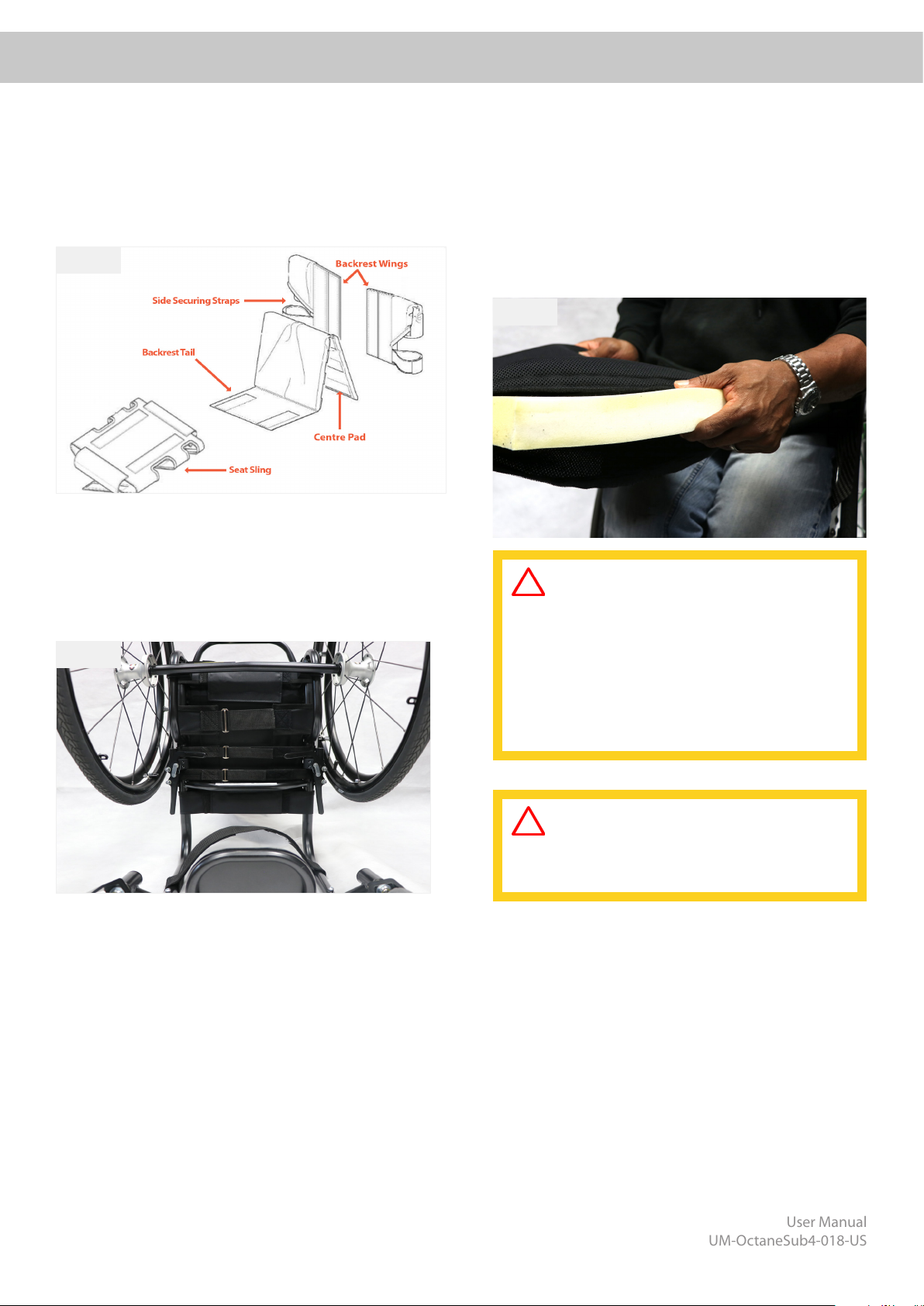
• If the seat and back sling are damaged, you must replace
them immediately.
• Do not lift or carry the wheelchair by the back tubes or
the push handles.
• Be careful with re, in particular with burning cigarettes.
Seat and back slings can be set alight.
• Always make sure that the quick-release axles on the rear
wheels are set properly and are locked in place. If the
button on the quick-release axle is not pressed in, the
rear wheel cannot be removed.
• In particular when using lightweight metal hand rims,
ngers will easily become hot when braking from a high
speed or on long inclines.
• If the wheelchair is subject to direct sunlight for a long
period of time, then parts of the wheelchair (e.g. frame,
leg rests, brakes and side guards) may become hot
(>41°C).
• To avoid hand injuries do not grab in between the spokes
or between the rear wheel and wheel lock when driving
the wheelchair.
• Do not use the wheelchair on slopes > 5°.
• The dynamic safe slope is dependent on the chair
conguration, the user’s abilities and the style of riding.
As the user’s abilities and style of riding cannot be
pre-determined then the max safe slope cannot be
determined. Therefore, this must be determined by
the user with the assistance of an attendant to prevent
tipping. It is strongly recommended that inexperienced
users have anti-tips tted.
• Do not use your wheelchair on muddy or icy ground.
• Do not use your wheelchair where pedestrians are not
allowed.
• The wheelchair should be used with caution in heavy
rain, snow, slippery, or unsound surfaces.
• Do not use the wheelchair in hazardous environments.
• Anti-tip tubes should prevent the chair tipping over
backwards unintentionally. Under no circumstances
should they take the place of transit wheels, and be
used to transport a person in a wheelchair with the rear
wheels removed.
• With extreme settings (e.g. rear wheels in the most
forward position) and less than perfect posture, the
wheelchair may tip over even on a level surface.
• Do not hang heavy items such as shopping bags or
backpacks, on the push handles, head rest or backrest
of the wheelchair. These can change the tipping point
and there is a risk of tipping backwards.
• When reaching for objects which are in front of, to the
side or behind the wheelchair, make sure that you do
not lean too far out of the wheelchair. If you do it can
change the centre of gravity there is a risk of tipping or
rolling over.
• Only use your wheelchair properly. For example, avoid
travelling against an obstacle without braking (step,
kerb edge) or dropping down gaps, or using escalators.
• Only attempt stairs with the help of an attendant. There
is equipment available to help you, e.g. climbing ramps
or lifts, please use them. If there is no such equipment
available, then the wheelchair must be tipped and
pushed over the steps (2 helpers).
• In general, any anti-tip tubes tted must be set
beforehand, so that they cannot touch the steps, as
otherwise this could lead to a serious fall. Afterwards
the anti-tip tubes must be set back to their correct
position.
• Make sure that the attendant only holds the wheelchair
using securely mounted parts (e.g. not on the footrests
or the side guards).
• When using the lifting ramp make sure that the anti-tip
tubes tted are positioned outside the danger area.
• Secure your wheelchair on uneven ground or when
transferring (e.g. into a car) by using the wheel locks.
• The wheel locks will only work if there is sucient tyre
pressure and if the correct setting has been made (see
the Chapter on“Wheel locks”).
• When it is dark, please wear light clothing or clothing
with reectors, so that you can be seen more easily.
Make sure that the reectors on the side and back
of the wheelchair are clearly visible. We would also
recommend that you t an active light.
• Adjustments to your wheelchair, especially to security-
relevant components as for example wheel-locks,
anti-tip or backrest must be performed by authorized
dealers.
• It is recommended to clean and disinfect the entire
product, especially the upholstery, frequently.
• Do not tilt the wheelchair without assistance
• Do not reuse single use fasteners

User Manual
UM-OctaneSub4-018-US
Octane Sub4 User Manual |
8
Item
Initially
Inspect/
Adjust
Weekly
Inspect/
Adjust
Monthly
Inspect/
Adjust
Yearly
General
• Wheelchair rolls straight (no excessive drag or pull to one side)
• Inspect frame for cracks and damage
• Inspect all fasteners are secured
Seat and Back Upholstery
• Inspect for rips or sagging
• Inspect fastening aps to ensure they securely latch
Rear Wheels
• Adjustable axle position camber bar is securely tightened
• Quick/quad release axles lock properly
• No excessive side movement or binding when lifted and spun
Handrims
• Inspect for signs of rough edges or peeling
Spokes
• Inspect for bent or broken spokes
• All spokes uniformly tight
Front Castor
• Inspect wheel/fork assembly for proper tension by spinning castor; castor
should come to a gradual stop
• Loosen/tighten locknut if wheel wobbles noticeably or binds to a stop
• Wheel bearings are clean and free of moisture
CAUTION: As with any vehicle, the wheels and tyres should be checked
periodically for cracks and wear, and should be replaced when necessary
Tyres
• Inspect for at spots and wear
• If pneumatic tyres check for proper ination
CAUTION: As with any vehicle, the wheels and tyres should be checked
periodically for cracks and wear, and should be replaced when necessary
Cleaning
Wheel Locks
• Do not interfere with tyres when rolling
• Pivot points free of wear and looseness
• Wheel locks easy to engage
Safety Inspection Checklist
NOTE:
Regular cleaning will help to highlight any loose or worn parts and enhance the smooth operation of your
wheelchair. To operate properly and safely, your wheelchair must be cared for just like any other vehicle. Routine
maintenance will extend the life and eciency of your wheelchair. Initial adjustments should be made to suit your
personal body structure and preference. Thereafter follow these maintenance procedures. Outlined below:

User Manual
UM-OctaneSub4-018-US
Octane Sub4 User Manual |
9
Solutions
Chair veers right
Chair veers left
Slow turn or
performance
Castor utters
Squeaks
and rattles
Loose-ness in
chair
Check tyres for correct and equal pressure
Check for loose castor stem nuts
Check all xtures are secure and tight
Check spokes for tension
Check that both castors contact the ground at the same time
WARNING:
After adjusting, always make sure that parts are properly tightened BEFORE using the wheelchair. DO NOT over-
tighten hardware attaching to the frame. This could cause damage to the wheelchair.
Troubleshooting Guide Mechanical

User Manual
UM-OctaneSub4-018-US
Octane Sub4 User Manual |
10
1.1: Adjusting Seat
Remove the cushion from the wheelchair. The seat is
adjusted by increasing or decreasing the tension in the
straps on the underside of the seat (Fig 15). To remove,
release all the straps and remove.
Fig 15.
Fig 14.
WARNING:
The position of the footrest, camber tube and
rear seat height, as well as the tautness of the
back upholstery are directly related to the chair’s
stability. Any change to one or any combination
of the four may cause the chair to decrease in
stability. Use EXTREME caution when using a new
seating position for the rst time.
CAUTION:
Velcro used on upholstery may cause property
damage if contacted closely.
Procedure 1 - Upholstery
Procedure 1
Fig 16.
1.2: Adjusting Backrest
Remove the cushion and centre pad from wheelchair (Fig
14). The backrest is adjusted by increasing or decreasing the
tension on the straps at the back of the backrest. To remove,
release all the straps and remove.
1.3: Changing Cushion Cover
Remove cushion from the wheelchair. Open the Velcro
pocket at the rear of the cushion and remove or replace
foam as required. (Fig16).
The upholstery is fully adjustable and can be easily adjusted
to provide the correct balance and comfort in your new
wheelchair.

User Manual
UM-OctaneSub4-018-US
Octane Sub4 User Manual |
11
WARNING:
Changing the size of your rear wheels can seriously
aect the performance and stability of the wheelchair.
Procedure 2 - Rear Wheels
Procedure 2
Fig 18.
The rear wheels are quick release and are designed to be
removed and attached frequently. All rear wheels use
quick release axle pins to secure the wheels to the frame,
although these vary in length, they operate the same.
2.1: Removing/attaching rear wheels
Push the quick release button and pull the wheel
outwards. To install, push and hold the button and insert
the quick release axle pin into the axle until the pin clicks
into position. Ensure both wheels are fully engaged prior
to use.
2.2: Adjusting Quick release axle pin
Only adjust the quick release axle pin if the wheel does
not engage or the wheels feels loose. To adjust the length,
remove the axle pin from the wheel and by using 2 x
adjustable spanners/wrenches as per Figure 19, extend or
shorten the pin as required.
Fig 19.
A = Lengthen B = Shorten
WARNING:
Any adjustments to your quick release pins – then YOU
must ensure your wheels lock on both sides of your
wheelchair.
When attaching the rear wheels, always check that they
are securely mounted. Pull on the rear wheels to make
sure the detent pin / RGK cap of the quick release axle
are fully released before operating the wheelchair.
You should NOT be able to pull the rear wheel o.

User Manual
UM-OctaneSub4-018-US
Octane Sub4 User Manual |
12
Procedure 3 - Tyres and Inner Tubes
Procedure 3 & 4
Tyres will wear just like a car tyre and the time will depend on the type of use. It is recommended that both tyres are
changed once the tread fades. For pneumatic tyres, there is a risk that a puncture will occur and the inner tube will need
to be replaced in order to keep the wheelchair operational.
3.1: Changing the tyre
Remove the wheel from the wheelchair and release air
in the tube by pressing the small pin inside the valve, if a
Presta valve, then unscrew both the head and the securing
ring at base and press the top until air releases. Using
2 x tyre levers (supplied in the toolkit), unhook the tyre
completely from the wheel rim. Remove inner tube and tyre
from wheel rim.
To install the tyre, place one side of the new tyre on the
wheel rim. Then insert the inner tube inside the tyre and
align the valve with the wheel rim hole. Ensure there are
no kinks or uneven tension in the inner tube before putting
the second side of the tyre back on the wheel rim using the
tyre levers. Be careful not to pinch the inner tube. Once tyre
and inner tube are on the wheel rim, replace securing ring
(if applicable) then inate tyre a little. Adjust inner tube and
tyre so that they t nicely on the wheel rim and inate to the
recommended tyre pressure.
3.2: Changing the inner tube
Repeat the method above but do not remove tyre
completely, just remove inner tube. If problems continue,
remove tyre and inner tube and ensure there are no sharp
edges in the wheel rim which may be causing a puncture.
4.1: Adjusting Axle Tube position
To adjust the axle position, remove wheels. Using a 5mm
allen key for the toolkit, release the top screw on each side of
the axle clamp as shown in Fig 21 (A). Once released but still
intact, move the axle backward for more stability and move
forward for more tip. Tighten the top screws once position has
been set, and carefully use the chair as it where the rst time.
4.2: Replacing Axle tube
To replace the axle tube, remove wheels. Using a 5mm allen
key from the toolkit, release the bottom screw completely from
the axle clamp as shown in Fig 21 (B). Take note of the distance
between the axle clamp and the axle tube for set up of the
new axle tube. Slide new tube into the clamps and into the
same position as the old axle tube. The notch in the axle insert
must be at the top of the axle tube.
If the wheelchair feels slow after replacing the axle tube, rotate
the axle tube a little forwards or backwards to correct the
wheel alignment.
WARNING:
The position of the footrest, camber bar, as well as
the tautness of the back upholstery, are directly
related to the chair’s stability.
Any change to one or any combination of the
three may cause the chair to decrease in stability.
Use EXTREME caution when using a new seating
position for the rst time.
Fig 21.
A = Adjust Position
B = Remove and replace
Procedure 4 - Camber Bar
The Camber Axle or Camber Tube control your wheel position and your centre of gravity. It is very important to have this
set up for your requirements for performance and safety. Axle tube can be xed or adjustable. Fixed means this cannot
be adjusted and for a user who is experienced and knows their balance point. Adjustable position gives the user choice
and is ideal for less experienced users

User Manual
UM-OctaneSub4-018-US
Octane Sub4 User Manual |
13
Procedure 5 & 6
Procedure 6 - Wheel Locks
WARNING:
After any adjustments, repair or service and before use, make sure all attaching hardware is tightened securely –
otherwise injury or damaged may result. If wheel locks do not hold occupied wheelchair in place please adjust as
above, or contact your dealer – otherwise injury or damages may occur. The wheel locks are designed to work when
your wheelchair is static. Wheel locks should not be applied during use and tyre pressure should be as indicated on
the tyre.
Before adjusting or replacing any style of wheel lock ensure that the tyres are
inated to the recommended pressure as indicated on the tyre.
NOTE:
The wheel locks are adjustable in position to suit tyre changes and wear. As tyres
wear, the wheel lock may not hold the wheelchair as intended, so these need to be
adjusted to suit the tyre condition.
6.1: Adjusting Wheel locks
Using a 5mm Allen key from the toolkit, release the 2 screws in the clamp or on the
underside of the plate. Once the wheel lock is loose, reposition so that there is at
least 3mm of interference when the wheel lock is activated. Tighten securely and
repeat on the other side.
Procedure 5 - Castor Wheels and Forks
Castor Bearings must be tted by an authorised dealer.
Failure to do so will result in invalid warranty on the parts.
NOTE:
CAUTION:
DO NOT replace the front castor forks or
castor wheels with a dierent size other than
what was originally supplied on the chair.
By changing to a dierent size castor fork or
castor wheel will have an adverse eect on
the running of the chair and the end users
balance causing personal injury.
The castor wheels at the front of the wheelchair will wear just like care tyres and should be replaced when they visibly look
worn or cracks appear.
5.1: Changing castor wheels
Using 2 x 4mm allen keys from the toolkit, remove 1 of the 2 screws
in the centre of the castor wheel, as shown in Fig 22. Remove
the screw and slide out the castor axle with the other screw still
attached, noting any spacers and their positions. Install the new
castor wheel and slide the castor axle back through and secure with
the nal screw.
Fig 22.
5.1: Changing castor Fork
Remove the bolt at the back of the castor housing using a 4mm
Allen key from the toolkit. Then use the special spanner to undo the
castor fork assembly as pictured in Fig 22, whilst holiding the frame.
The entire castor assembly will unscrew giving you access to the
bearings and castor fork. Use the socket to release the nut which
will release the fork. When installing, screw in the housing as far as it
can go and line up the hole so the securing bolt can be tightened.

User Manual
UM-OctaneSub4-018-US
Octane Sub4 User Manual |
14
Procedure 7 & 8
WARNING:
The footrest assembly MUST be at least 40mm
above the ground/oor to avoid hitting protruding
objects when using this wheelchair.
Procedure 7 - Footrest
The footrest may need adjusting when you rst use the
wheelchair, if circumstances change or if fasteners come loose.
It is important to periodically check the height and adjust as
required.
7.1: Adjust footrest height
Before adjustment, take note of the height you have or require
and mark if necessary. Using a 4 or 5mm allen key from the
toolkit, release the 2 screws in the footrest clamps. Reposition
the footrest in the correct height and tighten the screws
securely.
7.2: Adjust the footrest angle
With an adjustable angle footrest, release the 2 x clamp screws
in the centre of the footplate using a 4mm allen key and 10mm
spanner from the toolkit. Reposition to the correct angle and
tighten the screws securely.
WARNING:
Your folding back MUST be locked securely in place
before using your wheelchair.
CAUTION:
This product contains moving parts. Beware of nger
trapping.
Procedure 8 - Folding Backrest
The backrest can be xed or folding and if a folding option
is chosen, the backrest can fold to make the chair smaller in
transport size.
8.1: Operating the folding backrest
Grab the pull cord and the back brace-bar together until the
backrest releases and moves forward. Release the pull cord
and continue to push forward until the pins click into position
securing the backrest in the folded position. To release, grab
the pull cord and back brace bar together and pull upright
until the backrest clicks into the original position
Fig 23.

User Manual
UM-OctaneSub4-018-US
Octane Sub4 User Manual |
15
Procedure 9
WARNING:
DO NOT attempt to lift the wheelchair by any
removable (detachable) parts i.e. Height adjustable
push handles, Fold-down push handles and Screw-
in push handles
Button Release
Flip-Down push handles
Screw-In push handles
Height Adjustable push handles
Procedure 9 - Push Handles
A range of push handles can be supplied on this wheelchair
for use by an attendant and operated as per the following
procedures.
9.1: Adjusting Height adjustable push handles
Release the over centre lever and position at the desired height
and then tighten the lever to secure. Repeat on the other side
to get uniform height between both handles.
9.3: Operating ip down push handles
Press the button underneath the handle and push the handle
down at the same time, repeat on other side. Pull up the
handle until it clicks into position to return to original position.
9.2: Screw in push handles
Screw in push handles can be removed by unscrewing
them from the back rest. To install, screw them in until
tight by hand.

User Manual
UM-OctaneSub4-018-US
Octane Sub4 User Manual |
16
Procedure 10
Procedure 10 - Anti-tips
An anti tip can be used to make the chair more stable and is
recommended by a health care professional.
10.1: Swing away anti-tip
To store the anti-tip, push down on the spring-loaded tube
until it releases from the housing. Swing 180 degrees under
the chair and into the locked position. To return to the
operating position, repeat and return the same way. To adjust
the length, press the button on the tube and lengthen or
shorter the wheel tube.
10.2: Single sport anti-tip
To remove anti-tip, remove quick release pin and remove tube.
The clamp attached to the frame is factory tted and cannot
removed unless by an approved wheelchair technician.
WARNING:
RGK strongly recommends ordering the anti-tips as
an additional safeguard for the wheelchair user.
Anti-tippers MUST be fully engaged. Ensure the
release button of the anti-tipper fully protrudes out of
the hole in the anti-tipper socket.
Ensure both anti-tippers are adjusted to the same
height.
WARNING:

User Manual
UM-OctaneSub4-018-US
Octane Sub4 User Manual |
17
Procedure 11 - Sideguards
Procedure 11
Sideguards support the user and prevent clothes from getting
dirty. Although these need little maintenance, replacement is
shown below.
11.1: Screw in sideguards
Remove the rear wheels. Using a 4mm allen key from the
toolkit, release the 3 screws in the sideguard. To install, secure
all screws but do not tighten until all are in position. Take care
not to cross thread the screws.
11.2: Lift out sideguards
Remove sideguards from receiver. Using a 4mm allen key from
the toolkit, release the 2 screws securing the sideguard to the
lift out post. To install, replace and tighten the 2 screws. Take
care not to cross thread the screws.
11.3: Fold at sideguards
Using a 3mm allen key from the toolkit, remove the 4
screws from the inside of the sideguard. To install, secure
all screws but do not tighten until all are in position. Take
care not to cross thread the screws.
11.4: Flip back sideguards
Using a 4mm allen key from the toolkit, release the screws
securing the sideguard to the lift out post. To install,
replace and tighten the 2 screws. Take care not to cross
thread the screws.

User Manual
UM-OctaneSub4-018-US
Octane Sub4 User Manual |
18
Transportation
DANGER:
There is risk of serious injury or death if this advice is
ignored.
Transportation
Transportation of your wheelchair within a vehicle
A wheelchair secured in a vehicle, will not provide the
equivalent of safety and security as a vehicle seating system.
We recommend that the user transfers to the vehicle seating.
It is recognised that’s this is not always practical for the user to
be transferred and in these circumstances where the user must
be transported whilst in the wheelchair the following advice
should be followed:
DANGER:
Conrm that your wheelchair is crash test suitable,
see serial number and tie down points on wheelchair,
Fig 11, Page 22.
Conrm the vehicle is suitably equipped to transport
a passenger in a wheelchair, and ensure the method
of access/egress is suitable for your wheelchair type.
The vehicle should have the oor strength to take
the combined weight of the user, the wheelchair and
accessories.
Sucient space should be available around the
wheelchair to enable clear access to attach, tighten
and release the wheelchair and occupant tie down
restraints and safety belts.
The occupant wheelchair must be located in
a forward facing position and secured by the
wheelchair tie down and occupant restraint straps
(WTORS tie downs meeting the requirements of ISO
10542 Part 2 or SAE J2249) in accordance with the
WTORS manufactures instructions.
The wheelchairs use in other positions within a
vehicle has not been tested e.g. transportation ins
the sideways or rearwards facing position and must
not be out under any circumstances.
The wheelchair should be secured by a tie down
restraint system, conforming to ISO 10542 or
SAE J2249 with non-adjustable front straps and
adjustable rear straps, which typically use Karabiner
clip/s, hooks and tongue and buckle ttings. These
restraints generally compromise of 4 individual
straps that are attached to each corner of the
wheelchair. Fig XX (picture of chair with tie down
point stickers)
The tie down restraints should be tted to the main
frame of the wheelchair as indicated in Fig XX (same
as point above), and not to any attachments or
accessories e.g. not around the spokes of wheels,
wheel locks, or footrests.
Tie down restraints should attach be attached
as close as possible at an angle of 45 degrees
and tightened securely in accordance with the
manufacturer’s instructions.
Alterations or substitutions must not be made to the
wheelchair tie down points or to structural, frame or
components without consulting the manufacturer.
Failure to do so will invalidate the ability of an RGK
wheelchair to be transported in a vehicle.
Both pelvic and upper torso restraint belts must
be used to restrain the occupant to rescue the
possibility of head and chest impacts with the
vehicle components and serious risk of injury to the
user and other vehicle components. The upper torso
restraint belt should be mounted to the vehicles
pillar – failure to do so will increase the risk of serious
abdominal injuries to the user.
A head restraint suitable for transportation must
be tted and positioned at all times during
transportation to ensure maximum safety.
Postural supports (lap belts/straps) should not be
used or relied on for the occupant restraint in a
moving vehicle unless they are labeled as a meeting
the requirements specied in ISO 7176-19:2001 or
SAE J2249.
The safety of the user during transportation depends
upon the diligence of the person securing the
tie-down restraints and they should have received
appropriate instructions and/or
training in their use.
Wherever possible remove and stow safely away
from the wheelchair all auxiliary equipment, for
example:
• Crutches, Loose cushions and Tray Tables.
• Articulating/elevating legrest should not be used
in the elevated position when the wheelchair and
user are being transported and the wheelchair is
restrained using Wheelchair Transport and Occupant
Restraints.
DANGER:

User Manual
UM-OctaneSub4-018-US
Octane Sub4 User Manual |
19
Transportation
Transportation
Reclining backrests should be returned to an upright
position.
The manual wheel locks must be rmly applied.
Restraints should be mounted to the vehicle “B”
pillar and should not be held away from the body by
wheelchair components such as armrest or wheels.
DANGER:
Occupant Restraints Instruction:
1. The pelvic restraint belt must be worn low across the front
of the pelvis so that the angle of the pelvic belt is within the
preferred zone of 30 to 75 degrees to the horizontal.
A steeper (greater) angle within the preferred zone is
desirable i.e. closer to, but never exceeding 75°.
2. The upper torso restraint belt must t over the shoulder
and across the chest.
Restraint belts must be adjusted as tightly as possible
consistent with user comfort.
Restraint belt webbing must not be twisted when in use.
The upper torso restraint belt must t over the shoulder and
across the shoulder.
3. The attachment points to the chair are the inner front side
frame just above the castor, and the rear side frame. The
straps are tted around the side frames at the intersection of
the horizontal and vertical frame tubes.
4. The tie down symbol (Fig. 10) on the wheelchair frame
indicates the position of the wheelchair restraint straps. The
straps are then tensioned after the front straps have been
tted to secure the wheelchair.
USER WEIGHT LESS THAN 22KG
When the user being transported is a child, less than 22 kg
mass and the vehicle involved has less than eight (8) seated
passengers it is recommended that they be transferred to
an UNCE Regulation 44 compliant child restraint system
(CRS).
This type of restraint system provides a more eective
occupant restraint system than the conventional 3 point
occupant restraint system and some CRS systems also
include additional postural supports to assist in maintaining
the position of the child when seated.
Parents or care providers may consider the option, in some
circumstances, for their child is to remain in their wheelchair
whilst in transport due to the level of posture control and
comfort provided by the set up in the wheelchair.
We would recommend in such circumstances that a risk
assessment be carried out by your attendant and relevant
competent persons.
Positioning of wheelchair tie down restraints on wheelchair:
1. Location of the front and rear tie down labels (Fig 11 &
12).
2. Position the front and rear wheelchair tie
down restraint to the tie down label.
Fig10.
Fig11.
Fig12.

User Manual
UM-OctaneSub4-018-US
Octane Sub4 User Manual |
20
Technical Data
Technical Data
*Weight excluding 3rd party items
Dimensions are subject to manufacturing tolerances.
Description Min Max
Overall length with leg rest (no wheels)
Overall width (seat width)
Folded height (only for chairs with folding backs)
Total mass (with wheels)
Mass of the heaviest part (Transport weight)
Static stability downhill
Static stability uphill
Static stability sideways
Seat plan angle
Eective seat depth
Seat surface height at front edge
Backrest angle
Backrest height
Footrest to seat distance
Leg to seat surface angle
Armrest to seat distance
Front location of armrest structure
Handrim diameter
Horizontal location of axle
Minimum turning radius
400mm 700mm
250mm 440mm
500mm 700mm
5.5kg 15kg*
N/A 5° of incline
N/A 5° of incline
N/A 5° of incline
0° 45° of tilt
250mm 440mm
380mm 520mm
- 10° of tilt 20° of tilt
150mm 400mm
200mm 520mm
70° of angle 90° of angle
150mm 300mm
N/A N/A
24’’-in 26’’-in
25mm 125mm
270mm N/A
3.5kg 12kg*
Other manuals for Octane Sub4
1
This manual suits for next models
1
Table of contents
Other RGK Wheelchair manuals
Popular Wheelchair manuals by other brands

Drive
Drive Sentra manual

Invacare
Invacare Motion Concepts MaTRx Seating Series installation instructions

Drive DeVilbiss Healthcare
Drive DeVilbiss Healthcare Silver Sport Wheelchair Instructions for use

Shoprider
Shoprider XtraLite Jiffy UL7WR user manual

HMN
HMN M2 Mini Standard user guide

Invacare
Invacare Spree XT Specifications