Page 6 of 22
HOW LONG WILL THE UV DISINFECTION SYSTEM LAST?
The UV system is supported by a manufacturer’s warranty (refer to page 21).There are a number of
factors that will affect the length of service the UV system will provide. These include but are not
limited to the water chemistry, the water quality, the water pressure, the water temperature (inlet and
outlet), the water usage pattern and the quality of maintenance. Refer to “Precautions” on page 5.
Note: Critical components within the system require periodic replacement.
WATER SUPPLIES
This UV system must be installed in accordance with this advice to be covered by the Rheem
warranty.
This UV system is manufactured to suit the water conditions of most public reticulated water supplies.
However, there are some known water chemistries which can have detrimental effects on the UV
system and its operation and / or life expectancy. If you are unsure of your water chemistry, you may
be able to obtain information from your local water supply authority. This UV system should only be
connected to a water supply which complies with these guidelines for the Rheem warranty to apply.
Note: Some water analysis reports may state the conductivity of the water rather than the level of total
dissolved solids. Conductivity, measured in microsiemens per centimetre (µS / cm), is directly
proportional to the TDS content of the water. TDS, in mg / L, is approximately 70% of the conductivity
in µS / cm.
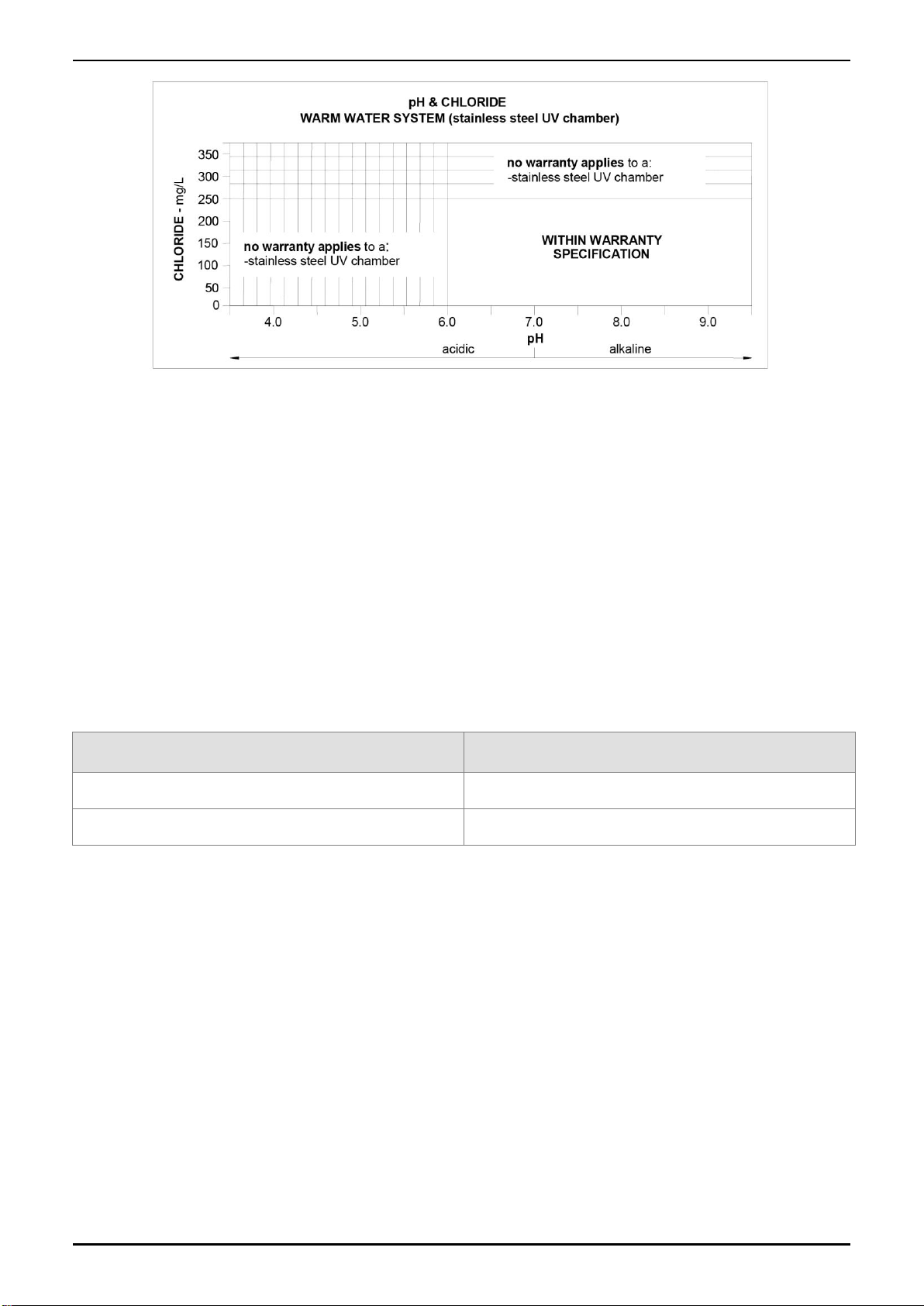
CHLORIDE AND PH
In a high chloride water supply, the water can corrode stainless steel parts and cause them to fail.
Where the chloride level exceeds 250 mg/L the Rheem warranty does not apply to the stainless steel
UV chamber in the UV disinfection system.
pH is a measure of whether the water is alkaline or acid. In an acidic water supply, the water can
attack stainless steel parts and cause them to fail.
Where the pH is less than 6.0 the Rheem warranty does not apply to the stainless steel UV chamber
in the ultra violet disinfection system.
Water with a pH less than 6.0 may be treated to raise the pH. The water supply from a rainwater tank
in a metropolitan area is likely to be corrosive due to the dissolution of atmospheric contaminants. This
may result in pH of less than 6.0. It is recommended an analysis on the water from a rainwater tank be
conducted prior to connecting this type of water supply to a system employing a stainless steel ultra
violet disinfection system.