i
i
Your safety, and the safety of others, is very important. The
proper and safe use of your Rhino® post driver is an important
responsibility and should be taken
seriously.
This entire book is lled with
important safety information. Please
read it carefully.
Keep this owner’s manual handy, so you
can refer to it at any time. This owner’s
manual is considered a permanent part of
the post driver and should remain with the
post driver if resold.
The information and specications includ-
ed in this publication were in effect at the
time of approval for printing. Rhino Tool
Company, Inc. reserves the right, however,
to discontinue or change specications or
design at any time without notice and with-
out incurring any obligation whatever. No
part of this publication may be reproduced
without written permission from Rhino
Tool Company.
To help you make informed decisions about safety, you will nd
important safety information in a variety of forms, including:
• Safety Labels on the post driver
• Safety Messages Preceded by a safety alert symbol and one of
three signal words, DANGER, WARNING, or CAUTION.
These signal words mean:
!DANGER
Immediate hazards that will result in
severe personal injury or death.
!WARNING
!DANGER
!CAUTION
IMPORTANT
NOTE
Hazards or unsafe practices that could
result in personal injury.
!
Hazards or unsafe practices that could result in injury,
product or property damage.
• Safety Headings such as IMPORTANT SAFETY
INFORMATION.
• Safety Section such as POST DRIVER SAFETY.
• Instructions how to use this post driver correctly and safely.
TAKE SAFETY SERIOUSLY
TAKE SAFETY SERIOUSLY
GPD-40 Fence Pro™Trouble Shooting
GPD-40 Fence Pro™Trouble Shooting
21
21
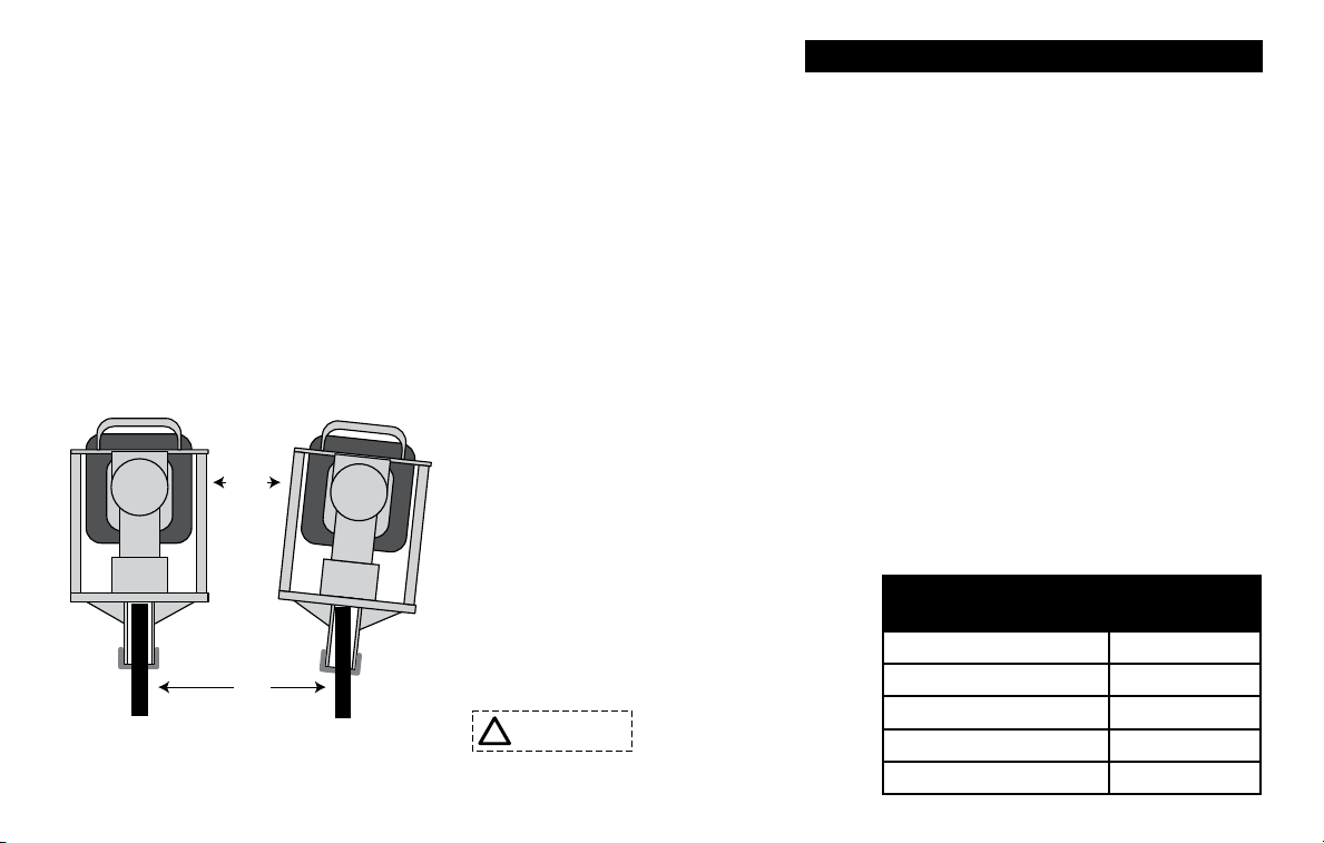
Post lodged in driver with adapter installed: Turn off the engine. Remove the Chuck-Lok™System’s locking nut from the master chuck and slide
down the post. Using the handles, lift postdriver upward, allowing the post adapter to slide out. If the pressure from the ared post does not allow you
to lift driver off the post, locate the pry gaps on the adapter base and use a athead screwdriver to pry them downward. Be careful not to damage the
master chuck threads. Once loosened, lift using the postdriver handles. As the two-piece adapter frees from the chuck tube they separate from the post.
Slide the locking nut off the post, reinsert the adapter, apply the locking nut and resume post driving.
Post lodged in master chuck: Remove the four 5/16” lower body bolts and separate the lower body casting from the driver body. Slide the lower body
casting down the post to expose the ared top of the post. With the proper cutting tool for the type of post, cut through the post below the ared portion.
Once the ared portion is removed, slide the lower body casting off the post and reassemble it to the driver. Please follow bolt tightening procedure and
use thread locker solution.
Recommendation: Do not use “thin-wall” or light gauge round post with the GPD-40 Ranch Pro™. It is very likely to flare this type of post at full throttle.
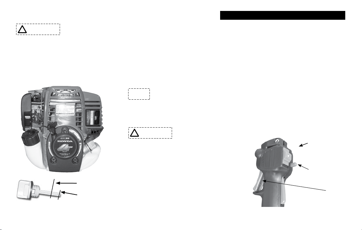
Drives post slow or sluggish engine performance: Typically this is resulting from improper driver storage or over-lling the oil causing the oil to
seep into the combustion chamber. Turn off the engine. Position the driver vertically, remove the dipstick to check oil level. (See page 6) If you need to
remove some oil, dispose of it properly. If oil is at proper level, follow the procedure listed in “Pull-start is frozen or hard to pull.” It also is good practice
to wipe clean the engine after use.
Pull-start is frozen or hard to pull: This typically results from oil seeping into the combustion chamber from improper driver storage or overlling the
oil reservoir of the engine. Remove spark plug and pull hand grip a several times until it pulls freely. Replace the spark plug. Check the oil level in oil
reservoir to ensure proper level (page 6). Follow starting procedure. It is not unusual, for blue smoke to be emitted from the engine, let the engine run
until smoke clears.
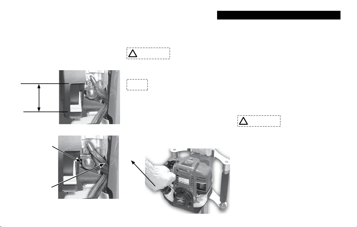
Proper Storage: When storing your GPD-40, do not lay it horizontally on the driver side or resting on the engine. If the unit cannot be stored securely in
the upright position, place the chuck on the at surface, lean it toward the engine side until it is supported by the shroud and chuck. This will position the
driver on an angle with the top handle at the topmost point.
Other problems or technical questions: Have your serial number handy and contact Rhino Tool Company. Phone: 309.853.5555 or Toll Free 866-
Post lodged in driver with adapter installed: Turn off the engine. Remove the Chuck-Lok™System’s locking nut from the master chuck and slide
down the post. Using the handles, lift postdriver upward, allowing the post adapter to slide out. If the pressure from the ared post does not allow you
to lift driver off the post, locate the pry gaps on the adapter base and use a athead screwdriver to pry them downward. Be careful not to damage the
master chuck threads. Once loosened, lift using the postdriver handles. As the two-piece adapter frees from the chuck tube they separate from the post.
Slide the locking nut off the post, reinsert the adapter, apply the locking nut and resume post driving.
Post lodged in master chuck: Remove the four 5/16” lower body bolts and separate the lower body casting from the driver body. Slide the lower body
casting down the post to expose the ared top of the post. With the proper cutting tool for the type of post, cut through the post below the ared portion.
Once the ared portion is removed, slide the lower body casting off the post and reassemble it to the driver. Please follow bolt tightening procedure and
use thread locker solution.
Recommendation: Do not use “thin-wall” or light gauge round post with the GPD-40 Ranch Pro™. It is very likely to flare this type of post at full throttle.
Drives post slow or sluggish engine performance: Typically this is resulting from improper driver storage or over-lling the oil causing the oil to
seep into the combustion chamber. Turn off the engine. Position the driver vertically, remove the dipstick to check oil level. (See page 6) If you need to
remove some oil, dispose of it properly. If oil is at proper level, follow the procedure listed in “Pull-start is frozen or hard to pull.” It also is good practice
to wipe clean the engine after use.
Pull-start is frozen or hard to pull: This typically results from oil seeping into the combustion chamber from improper driver storage or overlling the
oil reservoir of the engine. Remove spark plug and pull hand grip a several times until it pulls freely. Replace the spark plug. Check the oil level in oil
reservoir to ensure proper level (page 6). Follow starting procedure. It is not unusual, for blue smoke to be emitted from the engine, let the engine run
until smoke clears.
Proper Storage: When storing your GPD-40, do not lay it horizontally on the driver side or resting on the engine. If the unit cannot be stored securely in
the upright position, place the chuck on the at surface, lean it toward the engine side until it is supported by the shroud and chuck. This will position the
driver on an angle with the top handle at the topmost point.
Other problems or technical questions: Have your serial number handy and contact Rhino Tool Company. Phone: 309.853.5555 or Toll Free 866-