Technical Bulletin PAGE: 1/5
Shepherd-P1
16-Oct-18
RJ093003
Subject: Changed the installation procedure for
installing the proximity sensors. Prepared by: Y.Kurohashi
1st System Business Promotion Section, System
Business Department
Troubleshooting
Mechanical
Paper path
Product Safety
Part information
Electrical
Transmit/receive
Other ( )
Action required
Service manual revision
Retrofit information
Tier 2
Service Manual Revision
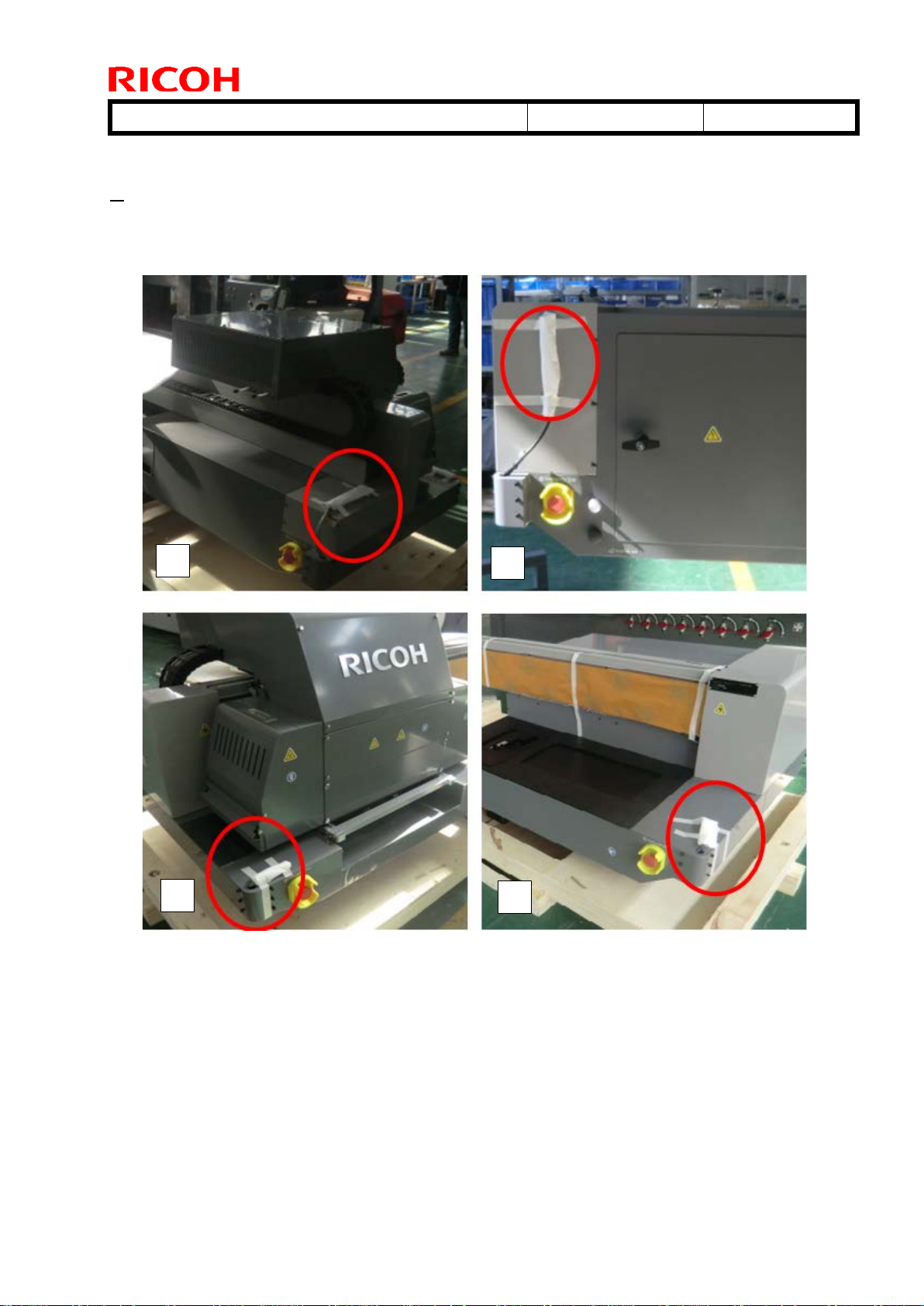
[2. Installation] - [Installing the Proximity Sensors]
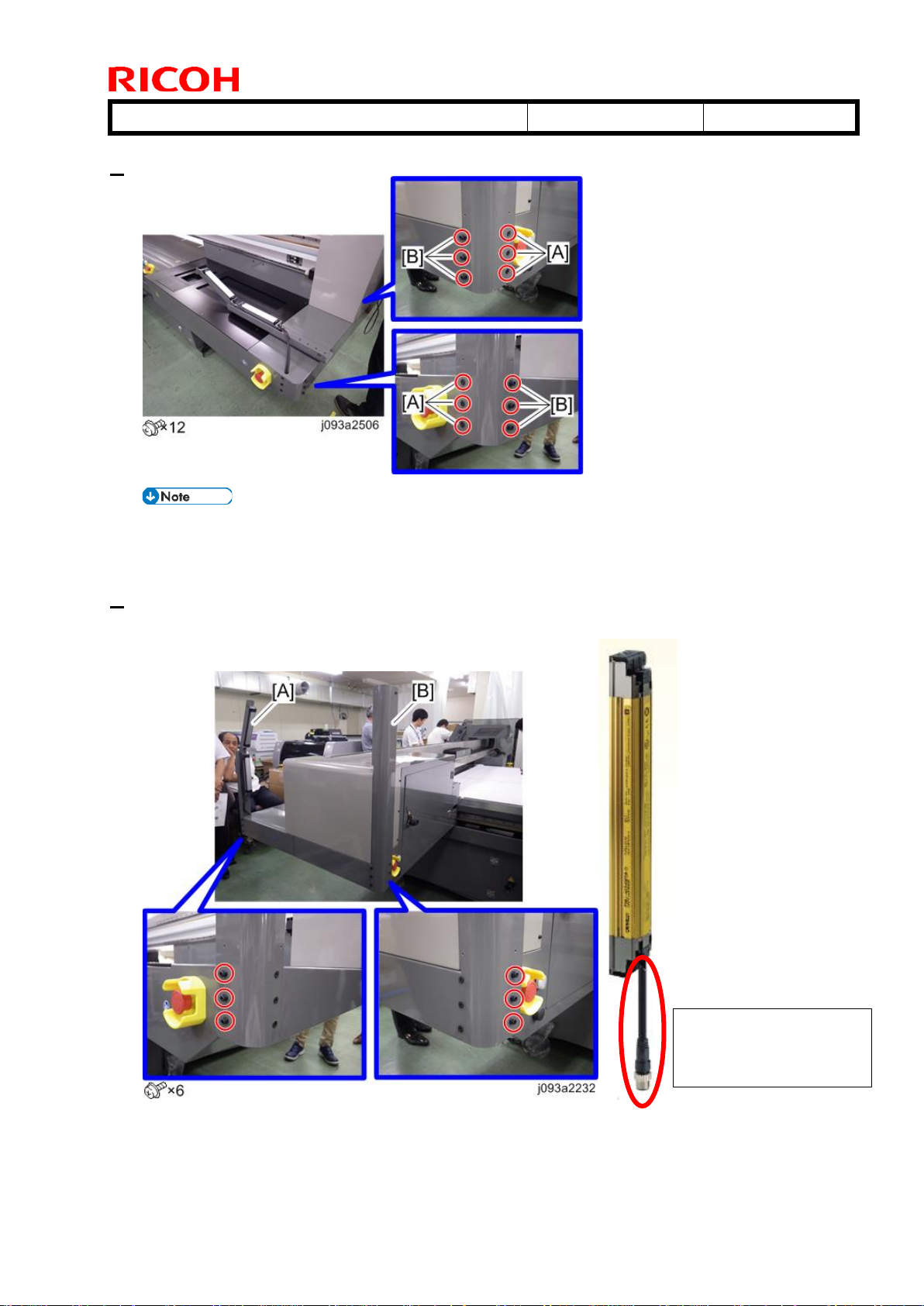
Changed the installation procedure for installing the proximity sensors.
1) Proximity Sensors have been changed as Accessories.
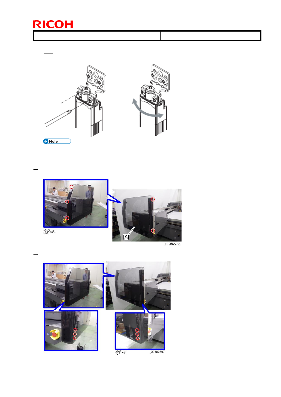
2) According to 1), installing procedure has been changed.
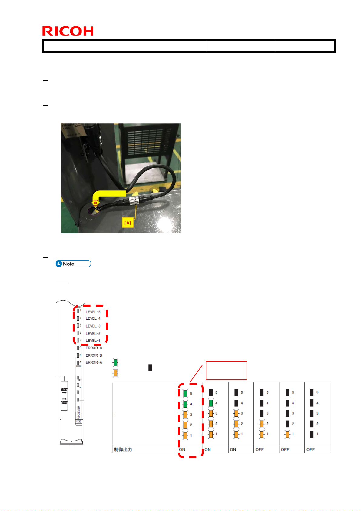
3) It requires Adjustment of light receiving amount after assembling the sensors.
The items in italics were corrected or added.
Procedure
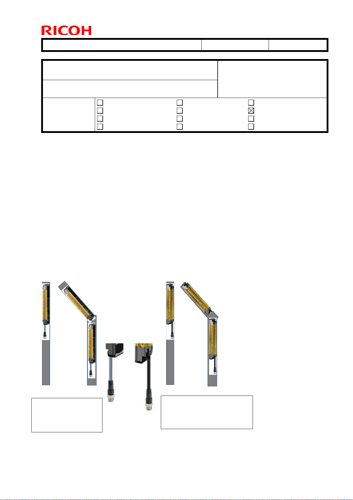
Additional accessories
[For Left Rear], [For Left Front], [For Right Rear], [For Right Front]
:
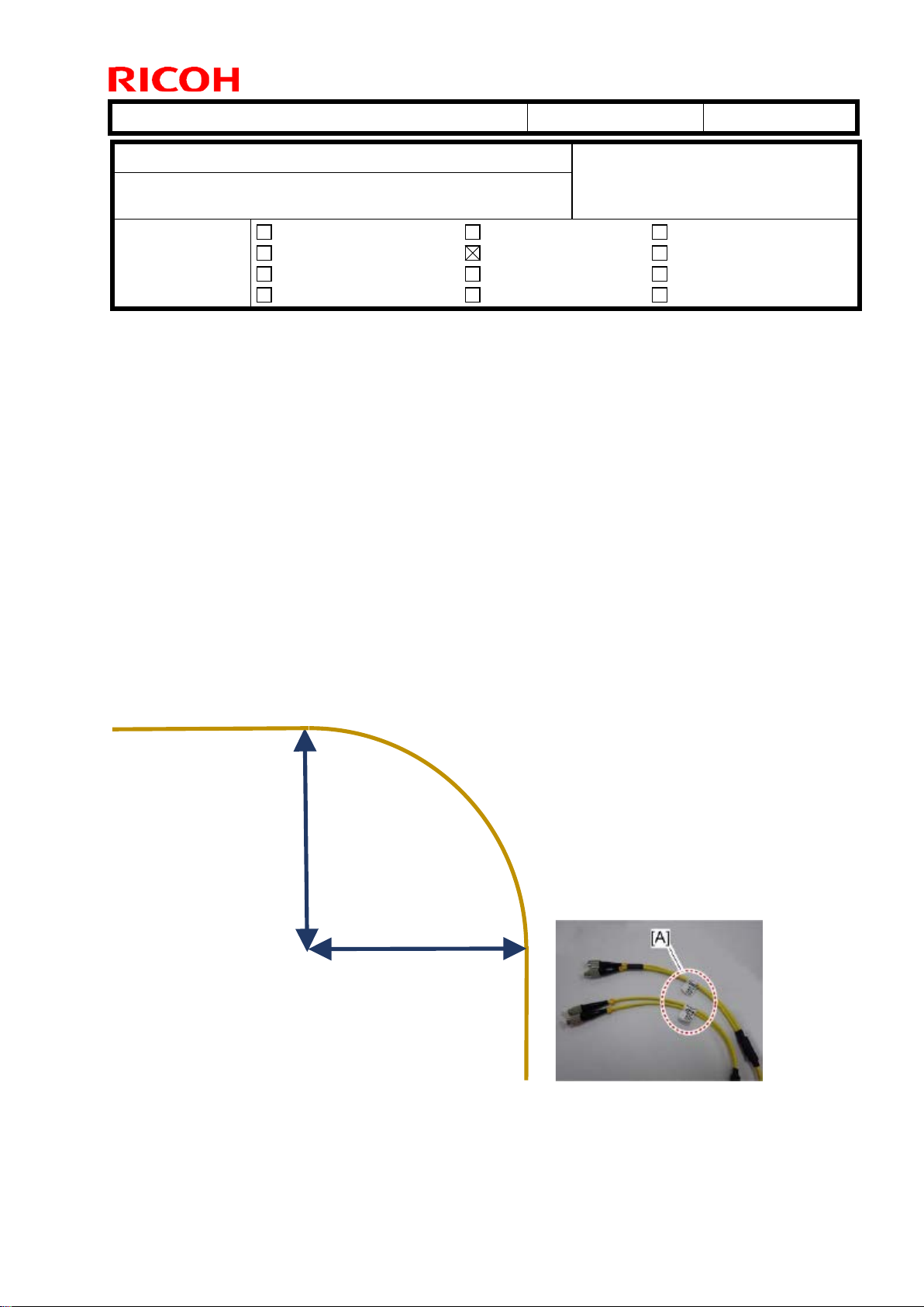
: Black Cable
: Gray Cable