Ricoh A220 User manual

Cardinal Bird
(Machine Code:A220)
Service Manual
–
Insert Version
–
The A220 machine is based on the A175/A176/A177/A191/A192
Copier.
Only the differences from the base copier are described in the
following pages. Therefore, this documentation should be treated
as an insert version of the base copier’s service manual. It should
always be utilized together with the base copier’s service manual.

INSERTION PROCEDURE OF SERVICE MANUAL
1. Replace the book spine tag with the new one.
2. Insert the A220 service manual after the A175/A176/A177/A191/A192
manual.

SECTION 1
OVERALL MACHINE
INFORMATION
1. SPECIFICATION
Configuration: Console
Copy Process: Dry electrostatic transfer system
Toner Supply Control: Fuzzy Control
Photoconductor: OPC drum
Originals: Sheet/Book
Original Size: Maximum A3/11" x 17"
Original Alignment: Left rear corner
Copy Paper Size: Maximum A3/11" x 17"
Minimum A5/51/2" x 81/2" (Tray)
B5/81/2" x 11" (1.5 k LCT)
A6/51/2" x 81/2" (By-pass)
Duplex Copying: Maximum A3/11" x 17"
Minimum A5/51/2" x 81/2" (sideways)
Copy Paper Weight: Paper tray: 52 ~ 128 g/m2, 14 ~ 34 lb
Bypass feed table: 52 ~ 157 g/m2, 14 ~ 42 lb
Duplex copying: 64 ~ 104 g/m2, 17 ~ 24 lb
Reproduction Ratios: 4 Enlargement and 6 Reduction
A4/A3 Version LT/LDG Version
Enlargement
200%
141%
122%
115%
200%
155%
129%
121%
Full Size 100% 100%
Reduction
93%
82%
75%
71%
65%
50%
93%
85%
77%
74%
65%
50%
Overall
Information
30 June 1997 SPECIFICATION
1-1
Power Source: 115 V, 60 Hz, more than 20 A (for N.A)
220 ~ 240 V, 50 Hz/60 Hz, more than 10 A (for
Europe and Asia)
Power Consumption: A220 copier
Copier only Full system*1
Warm up 0.90 kVA 0.92 kVA
Stand-by*20.22 kVA 0.24 kVA
Low Power mode*20.19 kVA 0.21 kVA
Copying 1.20 kVA 1.20 kVA
Maximum 1.45 kVA 1.50 kVA
*1Full System:
•Mainframe with dual job feeder, floor type
sorter stapler and 3,500-sheet large capacity
tray
•Mainframe with recirculating document
handler, finisher and 3,500-sheet large
capacity tray
*2When the anti-condensation heaters are off.
Noise Emission: Sound Pressure Level:
The measurements are made according to
ISO7779
A220 copier
Sound pressure level (The measurements are made according to ISO 7779 at
the operator position.)
Sound power level (The measurements are made according to ISO 7779.)
(average)
Copier only
Stand-by less than 34 dB (A)
Copying less than 57 dB (A)
Copier only
Stand-by less than 48 dB (A)
Copying less than 71 dB (A)
SPECIFICATION 30 June 1997
1-2

Dimensions:
Width Depth Height
Copier only 690 mm
27.2" 690 mm
27.2" 980 mm
38.6"
Copier with dual job feeder, sorter stapler, and
3,500-sheet large capacity tray 1,659 mm
65.4" 690 mm
27.2 mm" 1,116 mm
43.9"
Copier with dual job feeder, sorter stapler with
punch, and 3,500-sheet large capacity tray 1,659 mm
65.4" 690 mm
27.2" 1,113 mm
43.9
Copier with recirculating document handler,
finisher, and 3,500-sheet large capacity tray 1,764 mm
65.9" 690 mm
27.2" 1,112 mm
43.8"
Weight: Copier only:(Without the optional platen cover
= Approximately 2 kg)
Two-Tray version copier: Approximately 152 kg
Three-Tray version copiers: Approximately 162 kg
Zoom: From 50% to 200% in 1% steps
Copying Speed:
Warm-up Time: Less than 5 minutes (20°C)
First Copy Time:
(A4/81/2: x 11" sideways
from the 1st feed station)
3.1 seconds
Copy Number Input: Number keys, 1 to 999 (count up or count down)
Manual Image Density
Selection: 7 steps
Automatic Reset: 1 minute standard setting; can also be set from 1
second to 999 seconds or no auto reset.
Copy Paper Capacity: •By-pass feed table: approximately 50 sheets
•Paper tray: approximately 550 sheets
•Large capacity tray: approximately 1500
sheets
Toner Replenishment: 1,100 g/cartridge
A4/LT (sideways) A3/DLT B4/LG
A220 copier 51 (A4)
50 (LT) 26 32
Overall
Information
30 June 1997 SPECIFICATION
1-3

Optional Equipment: •Platen cover (A528-04)
•Dual job feeder (A610)
•Recirculating document handler (A607)
•20 bin sorter stapler (Floor type) (A606-17:
Ricoh, -22: NRG, -15: Savin)
•Finisher (A608)
•3500-sheet Large capacity tray (A609)
•Receiving Tray (A446-05)
•Key Counter Bracket D (A509-03)
•20 bin sorter stapler (Floor type) with punch
(A606-57, -67: Ricoh, -52, -62: NRG , -55:
Savin)
•Editing sheet (spare part)
SPECIFICATION 30 June 1997
1-4

2. MACHINE CONFIGURATION
2.1 COPIER OVERVIEW
There are two types of mainframe.
A220 - (10, 17, 20, 29:) copiers
Three 550-sheet paper trays
Optional 3,500-sheet large capacity
tray
A220 - (22: china) copier
Two 550-sheet paper trays
storage tray
Optional 3,500-sheet large capacity
tray
550
550
550
(3,500)
A220V500.img
(3,500)
550
550
storage
A220V501.img
Overall
Information
30 June 1997 MACHINE CONFIGURATION
1-5

2.2 SYSTEM OVERVIEW
DJF version
(Mainframe type with dual job feeder and floor type sorter stapler. The
mainframe in the illustration below is the two-tray version.)
RDH version
(The mainframe with recirculating document handler and finisher.
The mainframe in the illustration below is the two-tray version.)
Dual job feeder (A610)
3,500-sheets
large capacity
tray (A609)
Floor type sorter
stapler (A60617,
22, 15) or Floor
type sorter stapler
with punch (A60657,
67, 52, 62, 55)
A220V502.img
3,500-sheets
large capacity
tray (A609)
Recirculating document handler (A607)
Finisher (A608)
A220V503.img
MACHINE CONFIGURATION 30 June 1997
1-6

4. MECHANICAL COMPONENT LAYOUT
5. DRIVE LAYOUT
6. PAPER PATH
As indicated in the machine configuration section, there are neither
1,500-sheet LCT or 4th feed station versions. Refer to the
A175/A176/A177/A191/A192 service manual by ignoring these feed stations.
7. ELECTRICAL COMPONENT DESCRIPTION
There are no 1,500-sheet LCT, 4th tray, tandem tray, 60 CPM, or 70 CPM
versions. Refer to the A175/A176/A177/A191/A192 service manual. You can
find those components, which are not used for the A220 copier because the
notes for the various versions are indicated in the component name column.
The versions except for the A220-22 machine also have the following
components.
Symbol Name Function Index No.
M18 3rd Lift Raises the bottom plate in the 3rd
paper tray. 94
SW8 3rd Tray Set Detects if the 3rd tray is set or not. 84
S38 3rd Paper Near End Informs the CPU when the 3rd
cassette is in near end condition. 79
MECHANICAL COMPONENT LAYOUT
DRIVE LAYOUT
PAPER PATH
ELECTRICAL COMPONENT DESCRIPTION
30 June 1997
Overall
Information
1-7

SECTION 2
DETAILED SECTION
DESCRIPTIONS

4. DEVELOPMENT UNIT
Illustration Correction for the Paddle Roller (service manual page 2-46 and
2-48 of the A175/A176/A177/A191/A192 copiers)
The illustration for the paddle roller on page 2-46 and 2-48 is incorrect.
Please correct your service manuals, as shown below. This correction have
been already issued for the A175/A176/A177/A191/A192 copiers.
Incorrect
Correct
A220D507.wmf
A220D502.wmf A220D503.wmf
A220D504.wmf
A220D505.wmf A220D506.wmf
Detailed
Descriptions
30 June 1997 DEVELOPMENT UNIT
2-1

6. PAPER FEED
6.1 OVERVIEW
This model has two or three drawer tray paper feed stations.
The following table shows the configuration of each feed stations of the
copiers.
Feed station A220 - 10, 17, 20, 29
three tray copiers A220 - 22
two tray copiers
1st 550 sheets tray 550 sheets tray
2nd 550 sheets universal tray 550 sheets universal tray
3rd 550 sheets tray storage tray
Paper can also be fed using the by-pass feed table which has an
independent feed mechanism. The by-pass feed table can hold 50 sheets of
paper.
All feed stations use an FRR feed system. Rotation of the pick-up roller [A]
drives the top sheets of paper from each tray to the feed [B] and the
separation [C] rollers. The feed and separation rollers then take over paper
drive. If more than one sheet is fed by the pick-up roller, the separation rollers
rotates in the opposite direction and prevents all but the top sheet from
passing through to the registration rollers.
[A]
[B]
[A] [C]
[B]
A220D500.wmf
PAPER FEED 30 June 1997
2-2

6.8 PAPER LIFT MECHANISM
When the tray is set in the machine, the machine detects this condition by
using several detection methods as shown in the table:
Feed station
1st Tray set switch
2nd Paper size switch
3rd Tray set switch (not used for storage tray version)
When the machine detects that the paper tray is set in the machine, the lift
motor [A] rotates and the coupling gear [B] on the tray lift motor engages the
pin [C] of the lift arm shaft [D], then turns the tray lift arm [E] to lift the tray
bottom plate [F].
[A]
[C]
[B]
[D]
[E]
[F]
A220D501.wmf
Detailed
Descriptions
30 June 1997 PAPER FEED
2-3

9. ENERGY STAR COMPLIANT MACHINES
(North American version only)
The lower power timer and the auto off periods have been revised.
Lower power timer: The copier enters Low Power mode automatically at the
selected time after your job is finished.
The maximum limit of the selectable time has been changed from 120
minutes to 240 minutes.
Auto off timer: To conserve energy, this copier automatically turns off at the
selected time after the last copying job has been completed.
The maximum limit of the selectable time has been changed from 120
minutes to 240 minutes.
Refer to the A175/A176/A177/A191/A192 service manual for the other things.
ENERGY STAR COMPLIANT MACHINES
(North American version only) 30 June 1997
2-4

SECTION 3
INSTALLATION

2. COPIER INSTALLATION
2.1 ACCESSORY CHECK
Check the quantity and condition of the accessories in the box according to
the following list:
Description Q’ty
1. Sensor Cover ................................................................... 1
2. Flat Head Screw 4 x 6...................................................... 1
3. Leveling Shoes................................................................. 2
Installation
30 June 1997 COPIER INSTALLATION
3-1
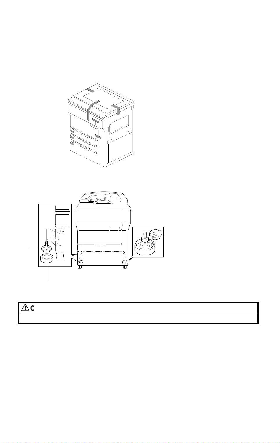
2.2 COPIER INSTALLATION PROCEDURE
NOTE: Since the installation procedure is not packed with the copier as
an accessory, always bring this manual with you.
CAUTION
When installing the copier, make sure that the copier is unplugged.
NOTE: Insert the leveling shoes [A] under the leveling feet [B] for the front
side, and level the machine before starting the installation. (The
leveling feet [B] can be screwed up or down.) Extra leveling shoes
(AH013008) and leveling feet (AH011004) are available as spare
parts.
1. Remove the tape strips.
NOTE: There are neither 1,500-sheet LCT or 4th feed station versions.
Refer to the A175/A176/A177/A191/A192 service manual for
installation.
A220I500.wmf
Note: There are two types of
bottom plate. One has
two leveling feet [B]
installed. The other has
four leveling feet.
[A]
[B]
A220I501.wmf
COPIER INSTALLATION 30 June 1997
3-2

SECTION 4
SERVICE TABLES

1. SERVICE REMARKS
1.11 FUSING UNIT
The following remark is not written in the A175/A176/A177/A191/A192
service manual.
However, this remark has been added as a A175/A176/A177/A191/A192
copiers service remark by RTB.
5. Silicon oil may slightly soak into the surface of the hot roller during
machine storage. The silicon oil may stick to the surface of the pressure
roller when the hot roller was in contact with the pressure roller at
installation. The pressure roller may slip due to the oil because the hot
and pressure rollers are new. Therefore, the smeared image may appear
on the leading edge at about 10 mm on the 1st copy. This is because the
hot roller is rubbing the leading edge of the copy on the pressure roller.
This symptom occurs only at the 1st copy after installation. Make sample
copies and make sure that the symptom does not recur after several
copies.
1.12 OTHERS
1. This machine has re-manufactured parts, which are selected from
dis-assembled machines in the Japanese domestic field. Note that there
are old and new parts in the machine.
Service
Tables
30 June 1997 SERVICE REMARKS
4-1
Other manuals for A220
1
Table of contents
Other Ricoh Industrial Equipment manuals


Popular Industrial Equipment manuals by other brands

Panasonic
Panasonic EXC18CS quick start guide

EINHELL
EINHELL LE-OFT 800 operating instructions

SMC Networks
SMC Networks MY2 Series manual

Livox
Livox Mid-360 user manual

JohnDow Industries
JohnDow Industries JDI-FST15 Operator's manual

HADEF
HADEF Gentry Crane 800 Installation, operating and maintenance instructions


