HBK FUSION User manual

BN2622-12
USER MANUAL
Version 2022.0

Although reasonable care has been taken to ensure the information in this document is accurate, nothing herein
can be construed to imply representation or warranty as to its accuracy, currency or completeness, nor is it
intended to form the basis of any contract.
Content is subject to change without notice – contact HBK for the latest version of this document.
HBK ADVANTAGE, HBK FUSION, HBK COMPANION and all other trademarks, service marks, trade names, logos and
product names are the property of Hottinger Brüel & Kjær A/S or a third-party company.
Copyright © Hottinger Brüel & Kjær. All rights reserved.
November 2022

Contents
About HBK FUSION 7
Release Info 8
About the system 8
The frame 8
The boards 8
The software 9
Optional mobile app 9
Barcodes 10
Health and safety information 11
Before use 11
End of use 11
Warnings 11
Safety instructions 12
Proper use 13
System integration 14
Handling of heavy loads 14
Declaration of conformity 15
Testing with high EMC immunity 16
Supported accessories 17
Software licensing 17
Acquiring a license 18
License checks 18
Contact HBK support 18
Getting Started 19
What's in the box? 19
Parts overview 20
Install HBK FUSION 21
Rack mounting 21
Tabletop mounting 22
Connecting sensors 23
Connect the sensor to a cable 23
Connect the sensor cable to an input board 30
Install HBK ADVANTAGE 31
Start the software 31
Discover your hardware in HBK ADVANTAGE 33
Reading the Devices explorer 33
(Optional) Import channel setup to HBK ADVANTAGE 34
Configure your hardware 35
Set up the hardware 35
Set up with HBK ADVANTAGE 37
Optional: Set up with HBK COMPANION 38
Using HBK COMPANION 39
The use of barcodes in the app 39
Configure channel parameters in HBK ADVANTAGE 40
Configure a bridge board (B201-10) 40

Configure a CCLD board (B301D-12) 40
Configure sensor parameters in HBK ADVANTAGE 41
When the sensor is a bridge 41
When the sensor is a resistance thermometer 42
When the sensor is voltage 42
When the sensor is a potentiometer 43
When the sensor is a CCLD transducer 43
When the sensor is a direct voltage transducer 44
Sensor characteristics 44
Sample rate 46
Bridge board sample rate/filter combinations 46
(Optional) Using OPC UA 48
Operating HBK FUSION 49
Qualified operating personnel 49
User control 49
Power 50
Connecting power 50
Disconnecting 50
Network setup 50
Direct connection to a PC 51
Network settings 51
Security 51
Volatile and non-volatile memory 51
Correct positioning during operation 52
Frames in a rack 52
Frames on a tabletop 52
Boards in the frame 52
Calibration 53
Synchronization 53
HBK FUSION's use of PTP 53
Temperature control 54
Frame fan control 54
Switching boards 54
Removing a board 55
Inserting a board 56
Check your hardware 58
Devices explorer in HBK ADVANTAGE 58
Using the Devices explorer 59
Devices table in HBK ADVANTAGE 59
Symbols in the table 60
Availability 60
User 60
Firmware version 61
LED status 61
Device web page 62
Information provided on the device web page 62
Functions provided on the device web page 63
Update firmware 63
Edit network settings 64

Edit synchronization settings 65
Edit fan settings 65
Fan modes of operation 66
Reset the device 66
Maintenance and care 67
Qualified maintenance personnel 67
Replacing air filters 68
Cleaning 68
Transportation, storage and disposal 68
Diagnostics and troubleshooting 70
Device troubleshooting 70
Network troubleshooting 70
Diagnostics in HBK ADVANTAGE 70
System monitor 71
Event log 72
Glossary 74


About HBK FUSION
ABOUT HBK FUSION
HBK introduces a new era of data acquisition hardware with the HBK FUSION system of frames and boards.
With universal inputs, scalable channel number, time-synchronised data and more, you gain high efficiency,
high performance and reliability, and reduce the time to results.
HBK FUSION data acquisition hardware enables a team to build a multi-domain system using a single front
end. Sound, vibration, strain, force, acceleration, displacement, pressure, and temperature – the HBK
FUSION hardware combines all relevant measurands to assess structural integrity in a single unit for best-in-
class data quality and high-efficiency testing.
The benefits of HBK FUSION include:
Reduced setup time
With the entire system, which includes HBK ADVANTAGE data acquisition software and HBK COMPANION
mobile app, you can reduce your total setup time by up to 30% with an easy and secure team collaboration
requiring just a few clicks to make the right decisions.
Open on all levels
Open ecosystem for integration of additional hardware or for integration into different software solutions to
achieve the best possible result.
Versatile system
The multi-physics application platform for various test and measurement applications in the time and
frequency domain.
Secure connection
lEncrypted and authenticated communication with HBK ADVANTAGE software.
lAuthentication of firmware before updating.
lLimitation of only one user per HBK FUSION board.
High performance and reliability
High system performance and throughput built on topnotch technology to secure continuous productive
testing.
HBK assured
One service contract for calibration, extended warranty, priority support and other benefits across the life
cycle of your equipment.
- 7 -

Release Info
Release Info
Version:
Version 2022.0
Release date:
November 2022
Manufacturer:
Hottinger Bruel & Kjaer A/S
Teknikerbyen 28
DK-2830 Virum
Denmark
Phone: +45 77412000
Fax: +45 77412100
Email: [email protected]
About the system
The HBK FUSION modular system allows the test equipment to easily grow with your testing needs. Start
with a single board in a frame, then add up to 15 more boards to expand your channel count. Add more
frames and boards as needed.
The frame
Each HF-16 frame houses up to 16 boards in a robust casing for industrial and rigourous everyday use.
Frames (with one or more boards) can be used for single front-end systems, or as part of a distributed
system.
Sample synchronisation, using precision time protocol (PTP), enables communication between the boards in
the frame and between frames on a system level.
Boards lock into place within the frame and can be easily swapped or removed without the use of any tools,
allowing you to configure and reconfigure your front end, or send a board for calibration.
See the HBK FUSION datasheet for specifications.
The boards
Bridge board
Bridge Board B201-10 is a 10-channel input board with a signal bandwidth up to 2kHz.
RJ45 channel connectors allow for quick and easy connection of sensors without soldering, and a patented
wiring configuration compensates for wire resistance, eliminating the need for shunting.
- 8 -

The software
The board supports DC and carrier-frequency excitation, allowing you to choose either a wider dynamic
range or a higher noise immunity, as well as a 5 – 24 V supply for active transducers.
Remote sensing is included to ensure measurement accuracy and enable ratiometric measurements.
See the HBK FUSION datasheet for specifications.
CCLD board
CCLD Board B301D-12 has 12 input channels and is designed for CCLD1transducers.
The benefit of CCLD is that the same wire is used for both the signal and the supply current. Even TEDS data
can be transmitted over the same wire. This enables the use of costeffective coaxial cables and SMB
connectors popularly used in general applications.
Both CCLD and direct input transducers are supported, including microphones and accelerometers, for
general sound and vibration measurements.
See the HBK FUSION datasheet for specifications.
Blank board
Blank Board B701 is functionless board that is required to fill a frame (if not all slots are in use by an input
board). For example, a single input board can be ordered and mounted in a frame, as long as 15 blank
boards are in the remaining slots.
The software
HBK ADVANTAGE provides for hardware configuration, basic data acquisition and a rich set of standard
functionalities paving the way into the future. It is a native Windows®installation with a 64-bit architecture
that supports multiple cores for the highest data throughput and smooth workflow.
The core application of HBK ADVANTAGE is initially designed for general purpose static and fatigue test
applications and will expand to include sound and vibration capabilities.
See the HBK ADVANTAGE datasheet for specifications.
Optional mobile app
The HBK COMPANION app enables you to set up a project ahead of testing by scanning devices and sensors
and identifying measurement positions and channel configurations. By importing the setup in HBK
ADVANTAGE, sensor and channel configuration is automated. Thanks to the synchronization between HBK
COMPANION and HBK ADVANTAGE, pictures and other documentation of the setup can be automatically
assigned to the sensors.
See the HBK COMPANION datasheet for specifications.
1Constant current line drive. Different manufacturers market transducers using the CCLD principle under different names, including
DeltaTron®and IEPE.
- 9 -

Barcodes
Barcodes
All hardware devices are labelled with barcodes – this includes supported HBK sensors. Many HBK sensors
are shipped with datasheets that also include the sensor barcodes.
Use these barcodes to:
lOpen the product datasheet or product page on hbkworld.com
lUsing HBK COMPANION app, scan to read device information such as serial number and type
number. You may also detect the sensor's measurement direction
- 10 -

Health and safety information
HEALTH AND SAFETY INFORMATION
This document contains information and warnings which must be followed to ensure safe operation and to
maintain the product in safe condition.
This product has been designed and tested in accordance with:
lEN/IEC61010-1 and ANSI/UL61010-1: Safety requirements for electrical equipment for
measurement, control and laboratory use
lEN55011:2016: Industrial, scientific and medical equipment – Radio-frequency (RF) disturbance
characteristics. Limits and methods of measurement
Group1: Devices that intentionally generate no more than 9kHz of RF energy
If the product is not used as intended, the protection provided by the product may be impaired.
Before use
When it is unpacked, check the product for visible signs of damage. If damage has occurred, the product
must not be operated.
If the product is damaged, operated without being acclimatized, or incorrectly stored or transported, the
protection provided by the product may be impaired.
End of use
HBK complies with the EU’s Waste Electrical and Electronic Equipment (WEEE) Directive, which
issues the following waste handling instructions:
lWaste electrical and electronic equipment or batteries may be returned to your local
HBK office for disposal.
lDo not dispose of electronic equipment or batteries as unsorted municipal waste.
Warnings
If the product is used outside the rated operating conditions or is not used as intended, the protection
provided by the product may be impaired.
According to EN55011, this is a Class A product, suitable for use in all areas, apart from the domestic
environment, where devices are directly connected to a low-voltage power supply network. This product
may cause radio interference in a domestic environment, and therefore you should take extra measures to
avoid this.
- 11 -

Safety instructions
Labelling
The product will be marked with this symbol when it is important that you refer to the
associated danger or warning statement given in this document.
This document uses this symbol when a danger or warning statement is applicable.
Hazardous Voltage/Electricity. Both the product and this document use this symbol when
there is a risk for shock or electrocution.
Danger Signals an imminent hazardous situation, which, if not avoided, will result in death or serious
injury.
Warning Signals a possibly hazardous situation, which, if not avoided, will result in death or serious
injury.
Caution Signals a hazardous situation, which, if not avoided, could result in minor or moderate injury
or damage to the product.
Notice Signals a situation or practice that requires attention, but does not directly result in personal
injury if ignored.
Safety instructions
Environmental hazards
Do not cover the fan outlets or the bottom of the device.
Do not operate on a tabletop without unfolding the feet.
If the product has been stored or transported in extreme temperatures, wait at least 2hours before
switching it on.
Do not expose the product to direct sunlight or intense sunlight for too long, including behind car windows.
Protect the product against direct contact with water and moisture. Should condensation form during
transportation or storage, acclimatize the product for at least 2hours before operating.
Do not operate the product above the maximum operational altitude of 2000m.
The product is designed for use in clean and dry rooms with pollution degree 2.
The product must not be operated where there is a risk of explosion or in an aggressive chemical
environment.
In the event of ambient temperatures outside the specified range, the system will take measures to ensure
proper cooling (increase fan speed) and eventually securely switch off the system if sufficient cooling cannot
be ensured.
- 12 -

Proper use
Electrical hazards
Voltages with no energy limit that exceed one of the following values are rated as dangerous according to
EN61010:
lAC voltage, 30Vrms value
lAC voltage, 42.4Vpeak value
lDC voltage, 60V
When applying dangerous contact voltages, you must comply with all related safety requirements.
Risk due to poor insulation of external circuits: only devices that comply with the requirements of IEC61010-
1, IEC61010-2-030 and IEC60950 may be connected.
To avoid injury from coming into contact with dangerously active electric potential: do not wear jewellery
(rings, watches, etc.) and do not touch any live parts. Comply with safety rules: isolate, secure, check, ground
and short-circuit, cover and safeguard.
Proper use
Connection
For devices connected to a network, safety precautions must be taken to ensure that line breaks and other
signal transmission interruptions do not occur in order to minimise data loss and other undefined states.
Only approved accessories can be used or connected to the product.
To disconnect the product and its power supply from the AC supply completely, unplug the mains power
cable.
Working safely
When it is unpacked, check the product for visible signs of damage. If damage has occurred, the product
must not be operated.
Proper and safe operation requires proper transportation, correct storage, siting and mounting and careful
operation. Follow all instructions in this manual to ensure the proper and safe operation of your product.
In the following situations, the product must be shut down and secured to prevent inadvertent operation:
lVisible signs of damage to the product
l(Audibly) loose parts in the product
lThe product no longer works
The covers protect the user from live parts and should only be removed by suitably qualified personnel for
maintenance and repair purposes. The product must not be operated with the covers removed.
At the rear of the product, there is a cover with non-functional slots. Do not remove during operation. Do
not attempt to use the slots.
- 13 -

System integration
System integration
If the product is integrated into a system, it is the responsibility of the system installer to keep the system
safe.
The scope of supply and performance of the product covers only a small area of measurement technology.
Before starting up the product in a system, a project planning and risk analysis must first be implemented,
taking into account all the safety aspects of measurement and automation technology so that residual
dangers are minimized. This particularly concerns personnel and machine protection. In the event of a fault,
the relevant precautions must establish safe operating conditions.
System integration must also take into account the relevant national and local accident prevention
regulations in plants where malfunctions could cause major damage, loss of data or even personal injury.
Additional risks may occur when the product is integrated into plants or systems and the protection
provided by the product may be impaired.
Handling of heavy loads
The EU’s Council Directive90/269/EEC – Manual Handling of Loads, lays down the minimum health and
safety requirements for the manual handling of loads where there is a risk particularly of back injury to
workers.
As the weight of the frame may exceed 24kg with 16boards installed (8.5kg without any boards), please
take appropriate actions before lifting the product.
The user may be at risk if:
lHe/she is physically unsuited to carry out the task in question.
lHe/she does not have adequate or appropriate knowledge or training.
Before lifting the product, refer to the occupational health and safety organization, or equivalent, in your
country for more information.
Remember, before lifting or carrying a heavy object, the following questions should be asked:
lCan one person lift this load safely, or do two people need to lift the load?
lHow far will the load have to be carried?
lIs the path clear of clutter, cords, slippery areas, overhangs, stairs, curbs or uneven surfaces?
lWill closed doors that need to be opened be encountered?
lOnce the load is lifted, will it block the carrier’s view?
lCan the load be broken down into smaller parts?
lShould the carrier wear gloves to get a better grip and to protect hands?
- 14 -

Declaration of conformity
Declaration of conformity
NOTE
The following is only guaranteed using accessories listed in this document.
Conforms with the following national and international standards or technical specifications:
The CE marking is the manufacturer's declaration that the product meets the
requirements of the applicable EU directives.
RCM mark indicates compliance with applicable ACMA technical standards – that is, for
telecommunications, radio communications, EMC and EME.
China RoHS mark indicates compliance with administrative measures on the control of
pollution caused by electronic information products according to the Ministry of
Information Industries of the People’s Republic of China.
WEEE mark indicates compliance with the EU WEEE Directive.
The UKCA (UK Conformity Assessed) marking is a UK product marking that is used for
goods being placed on the market in Great Britain.
Safety EN/IEC61010-1 and ANSI/UL61010-1: Safety requirements for electrical equipment for
measurement, control and laboratory use.
EMC Emission EN/IEC61326-1: Electrical equipment for measurement, control and laboratory use –
EMC requirements.
CISPR 11 and EN55011: Industrial, scientific and medical equipment. Radio-frequency
disturbance characteristics. Limits and methods of measurement.
CISPR32 and EN 55032: Radio disturbance characteristics of information technology
equipment. Class A Limits.
FCC Rules, Part 15: Complies with the limits for a Class A digital device.
This ISM device complies with Canadian ICES-001 (standard for interference-causing
equipment).
EMC Immunity EN/IEC61326-1: Electrical equipment for measurement, control and laboratory use –
EMC requirements.
Note: Please see this document for information on cables, connectors and shielding
concept to be applied to ensure the product EMC compliance.
Temperature EN/IEC60068-2-1: Environmental Testing. Cold.
EN/IEC60068-2-2: Environmental Testing. Dry Heat.
Operating Temperature: –20 to +60°C (–4 to 140°F) Storage Temperature: –40 to
+75°C (–40 to 167°F)
- 15 -

Testing with high EMC immunity
Humidity EN/IEC60068-2-78: Damp Heat: 5 to 95% RH (non-condensing)
Mechanical Non-operating:
IEC60068-2-6: Vibration: Accel.: 19.6m/s2(2gn); Dur.: 60min; Freq.: 5 to 500Hz; Dir.:
3axes
IEC60068-2-27: Shock: Accel.: 245m/s2(25gn); Pulse: 6ms; Impacts: 3 (pos/neg 3axes)
Operating:
IEC60068-2-6: Vibration: Accel.: 9.8m/s2(1gn); Dur.: 60min; Freq.: 5 to 500Hz; Dir.:
3axes
IEC60068-2-27: Shock: Accel.: 98.1m/s2(10gn); Pulse: 11ms; Impacts: 1000 (pos/neg
3axes)
Enclosure IEC60529: Protection provided by enclosures: IP20
Testing with high EMC immunity
The cable used for testing with high EMC immunity is a pairwise doubly shielded, 8-wire cable with the
following characteristics:
lThe cable houses three pairs of wires (black/blue, red/white, green/gray), each wrapped in a separate
shielding.
lTwo extra wires (purple and brown) are shielded individually.
lAll wires in the cable are bundled by an external braided shielding layer.
The following figure shows the wire configuration in such a cable:
- 16 -

Supported accessories
NOTE
For good EMC immunity, it is very important to keep the internal and the external shielding
galvanically isolated from each other.
Supported accessories
Each HBK FUSION delivery includes:
lThe relevant number of blank boards to ensure that all empty slots in the frame are filled
lLAN cable
lMains power cable
l4 × cross-head screws for rack mounting
The following additional accessories are available from HBK:
Item number Description
B701 Blank board
F1A-12 Detachable front panel for the 12-channel CCLD Board
DS-0003 Air filter (pack of 5 units)
To order new or replacement items, contact your local HBK representative.
Software licensing
HBK ADVANTAGE requires a valid license to run. A license grants a PC access to the software, based on the
PC's host ID and type of license:
lPaid license: A leased license for any paid features.
lFree license: A scaled-down version of the software that is free-of-charge.
Free licenses
A free license is a scaled-down version of the software offering basic features that allow you to try out the
software. Features that require a paid license are visible, but disabled. You can upgrade to a paid version at
any time.
- 17 -

Acquiring a license
What is available:
lHBK FUSION discovery and connection
lSupport for bridge, RTD (resistance temperature detector)/temperature, voltage and potentiometer
sensor setup
lY(t) display
lDigital indicator display
lManual data recording
lData recording in .bkc file format
What is not available:
lCustomizable column filters and sorting
lStrain gauge rosette calculations
lXY display
lPrediction lines
lTriggered data recording
lChannel table import from HBK COMPANION mobile app
lHardware setup export
Acquiring a license
You can upgrade to a paid license or renew an expired license in one of two ways:
lContact your HBK Global Customer Care agent
lRequest a license on the HBK website
With all licenses, you will receive an email that includes a license file containing your license key and, where
relevant, a specific number of tokens. Save the license file to a location on your PC or network. For more
tokens, contact your license administrator or HBK Customer Care agent.
You can find contact information for your local Customer Care office on the HBK website.
License checks
When you open HBK ADVANTAGE for the first time, you will have to configure your license.
Subsequently, license checks are performed every time you open the software to ensure your license is valid
and/or there are available tokens for you to use.
The system automatically generates alert messages when your license is about to expire.
Contact HBK support
For training and support, contact your local HBK representative.
- 18 -
Getting Started
GETTING STARTED
The following pages will help you get up and running with your new HBK FUSION hardware.
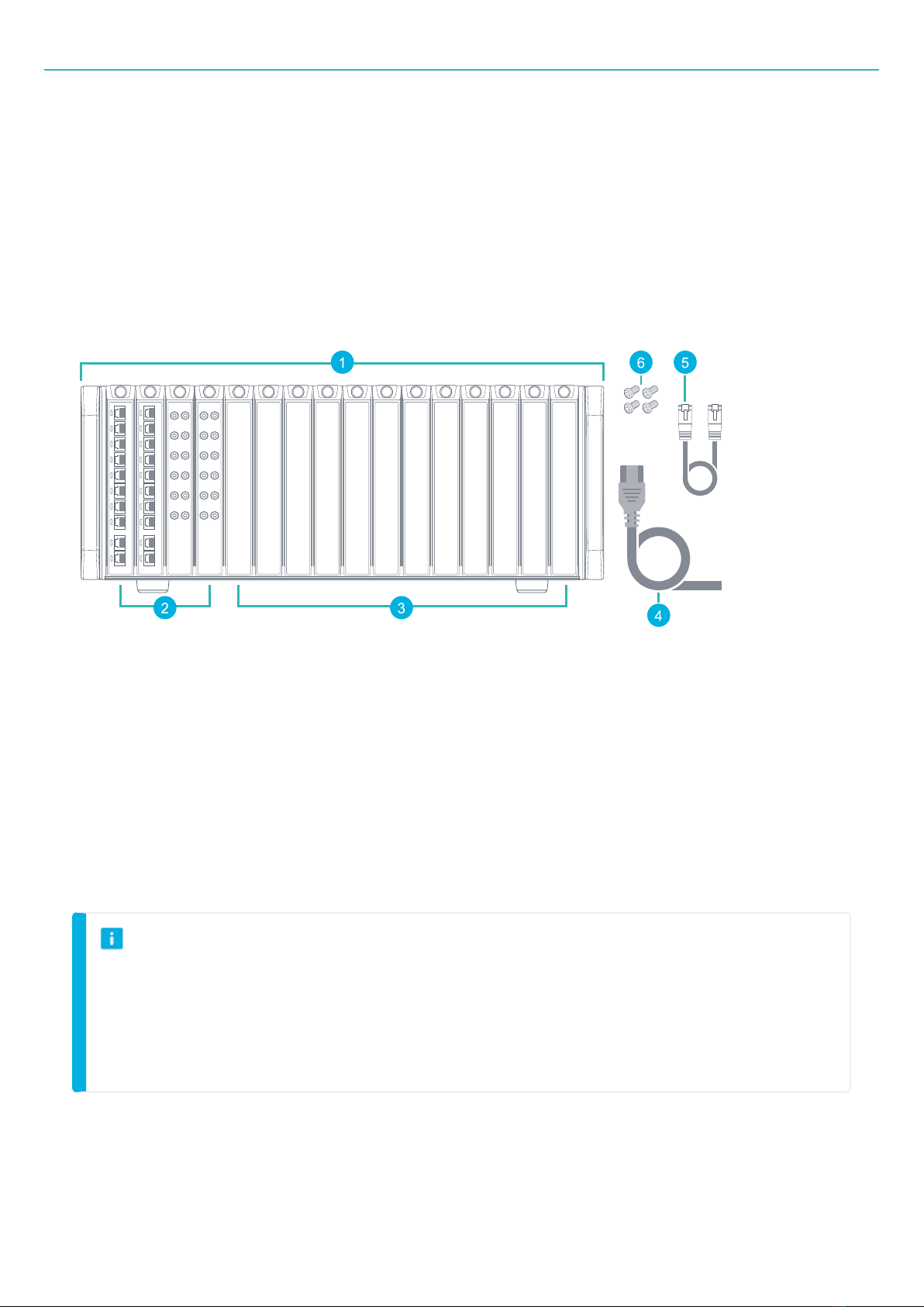
What's in the box?
1. Frame (housing)
2. Input boards
3. Blank boards
4. Power supply cable with plug
5. Ethernet cable
6. 4 × cross-head screws for rack mounting, screwdriver not included
NOTE
lAll slots must contain a board (input or blank) during operation.
lThe 16 slots can be filled with any combination of HBK FUSION boards.
lThe figure above shows a sample configuration. Your system may differ (all the same type or a
combination with or without blank boards).
- 19 -
Parts overview
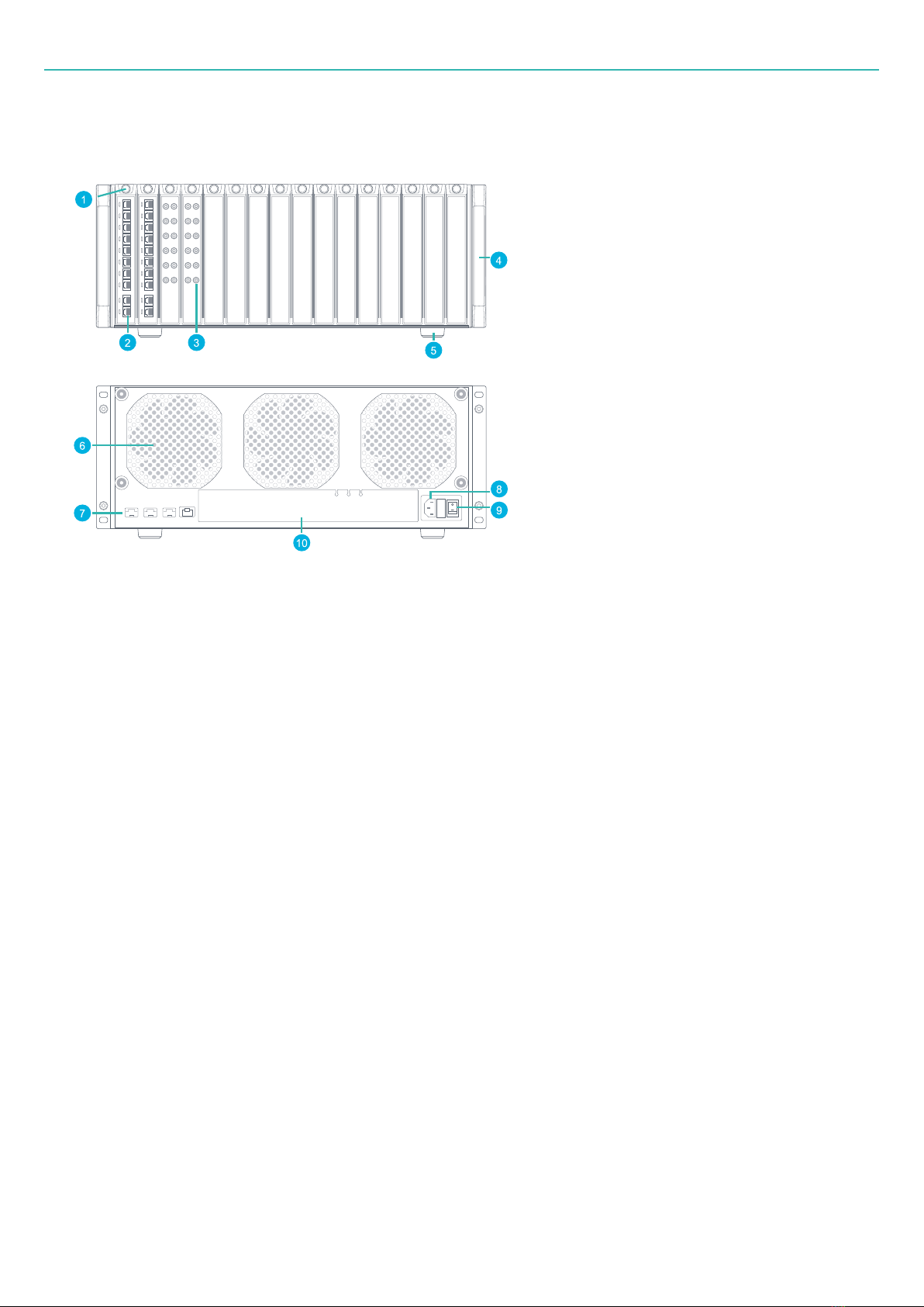
Parts overview
1. Board fastener
2. Input connectors
3. Input connectors
4. Plastic handle cover
5. Foot for tabletop mounting
6. Fan
7. Ethernet ports:
a. 1 × RJ45 (up to 2.5 Gbit/s)
b. 3 × optional SFP modules for optical/copper (up to 10 Gbit/s)
8. Power socket
9. On/Off switch
10. Cover with non-functional slots. Do not remove during operation. Do not attempt to use slots.
- 20 -
Table of contents
Other HBK Industrial Equipment manuals


