Ricoh Bridge Unit BU5010 Quick start guide

Bridge Unit BU5010
Machine Code: D778
Field Service Manual
October, 2014

Safety, Conventions, Trademarks
Conventions
Common Terms
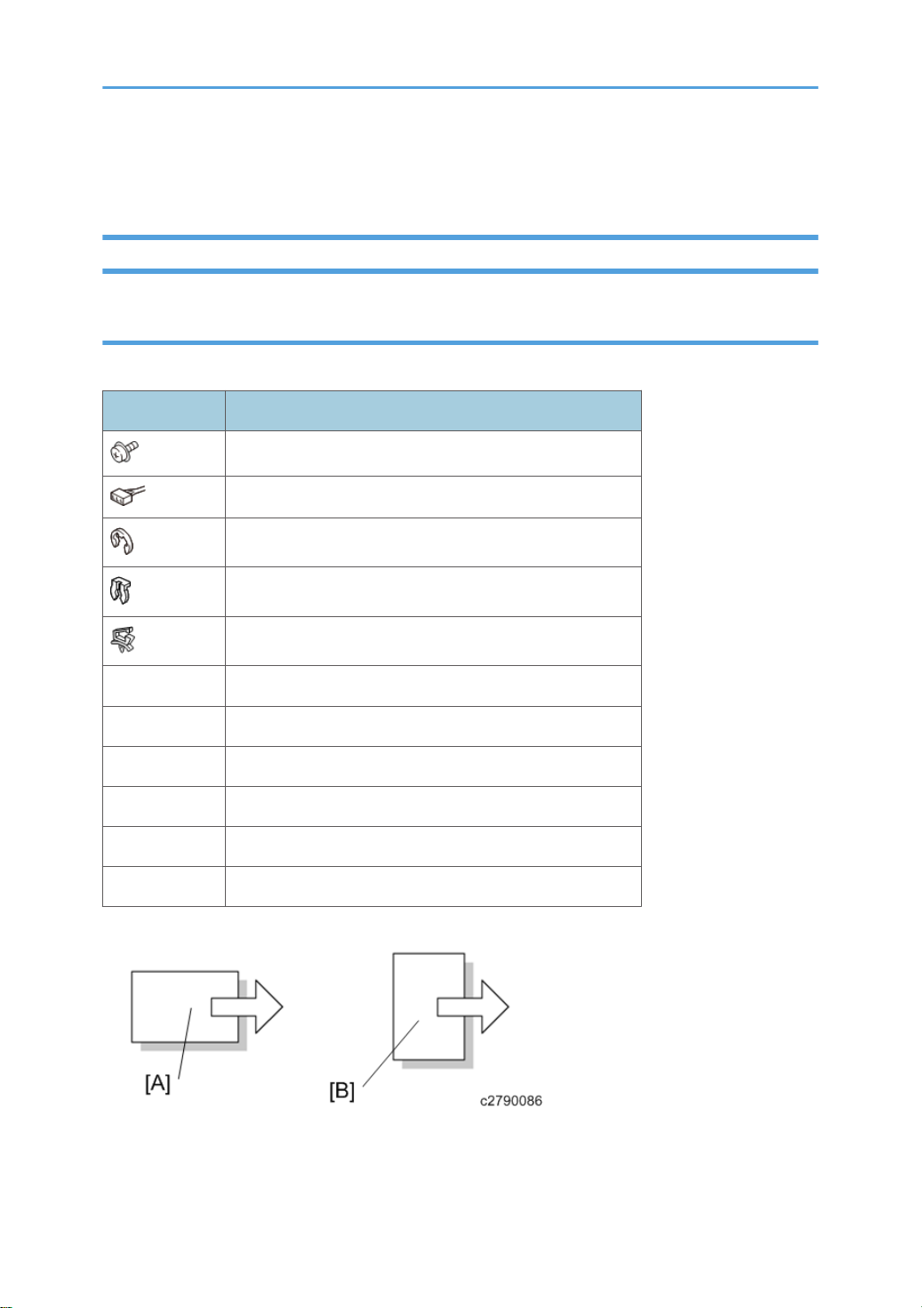
This is a list of symbols and abbreviations used in this manual.
Symbol What it means
Screw
Connector
E-ring
Clip ring
Harness clamp
FFC Flexible Film Cable
JG Junction Gate
LE Leading Edge of paper
LEF Long Edge Feed
SEF Short Edge Feed
TE Trailing Edge of paper
[A] Short Edge Feed (SEF)
[B] Long Edge Feed (LEF)
ta-c2p2_sm_d778_00165757_eng.xml 1
Warnings, Cautions, Notes
In this manual, the following important symbols and notations are used.
• A Warning indicates a potentially hazardous situation. Failure to obey a Warning could result in
death or serious injury.
• A Caution indicates a potentially hazardous situation. Failure to obey a Caution could result in
minor or moderate injury or damage to the machine or other property.
• Obey these guidelines to avoid problems such as misfeeds, damage to originals, loss of valuable
data and to prevent damage to the machine.
• This information provides tips and advice about how to best service the machine.
Responsibilities of the Customer Engineer
Reference Material for Maintenance
• Maintenance shall be done using the special tools and procedures prescribed for maintenance of
the machine described in the reference materials (service manuals, technical bulletins, operating
instructions, and safety guidelines for customer engineers).
• Use only consumable supplies and replacement parts designed for use of the machine.
The Aim of Anti-tip Components and Precautions
The anti-tip components are necessary for meeting the requirements of IEC60950-1, the international
standard for safety.
The aim of these components is to prevent the products, which are heavy in weight, from toppling as a
result of people running into or leaning onto the products, which can lead to serious accidents such as
persons becoming trapped under the product. (U.S.: UL60950-1, Europe: EN60950-1)
Therefore, removal of such components must always be with the consent of the customer.
Do not remove them at your own judgment.
2ta-c2p2_sm_d778_00165757_eng.xml

TABLE OF CONTENTS
Safety, Conventions, Trademarks......................................................................................................................1
Conventions.................................................................................................................................................... 1
Common Terms...................................................................................................................................... 1
Warnings, Cautions, Notes...........................................................................................................................2
Responsibilities of the Customer Engineer.................................................................................................... 2
Reference Material for Maintenance...................................................................................................2
The Aim of Anti-tip Components and Precautions....................................................................................... 2
1. Replacement and Adjustment
Detaching the Bridge Unit..................................................................................................................................5
Detaching the Upstream Unit.........................................................................................................................5
Detaching From the Downstream Unit.......................................................................................................... 7
Exterior Covers................................................................................................................................................. 10
Rear Cover................................................................................................................................................... 10
Top Cover.....................................................................................................................................................11
Right Rear Cover..........................................................................................................................................11
Rear Corner Cover...................................................................................................................................... 11
Front Corner Cover......................................................................................................................................12
Bridge Unit........................................................................................................................................................ 14
LCIT Connect Motor.................................................................................................................................... 14
Front Door Detection Switch....................................................................................................................... 15
LCIT Connect Entrance Sensor....................................................................................................................17
LCIT Connect Exit Sensor.............................................................................................................................18
Horizontal Transport Unit................................................................................................................................ 19
Horizontal Transport Entrance, Middle, Exit Sensor.................................................................................19
Horizontal Transport Entrance Motor........................................................................................................ 20
Horizontal Transport Exit Motor................................................................................................................. 21
Control Board...............................................................................................................................................23
Cooling Fan..................................................................................................................................................24
3

4

1. Replacement and Adjustment
Detaching the Bridge Unit
Detach the bridge unit [B] from the upstream unit [C] and downstream unit [A].
• If 2 vacuum feed LCITs are connected or 3 vacuum feed LCITs are connected, you can detach the
bridge unit with the same procedure.
Detaching the Upstream Unit
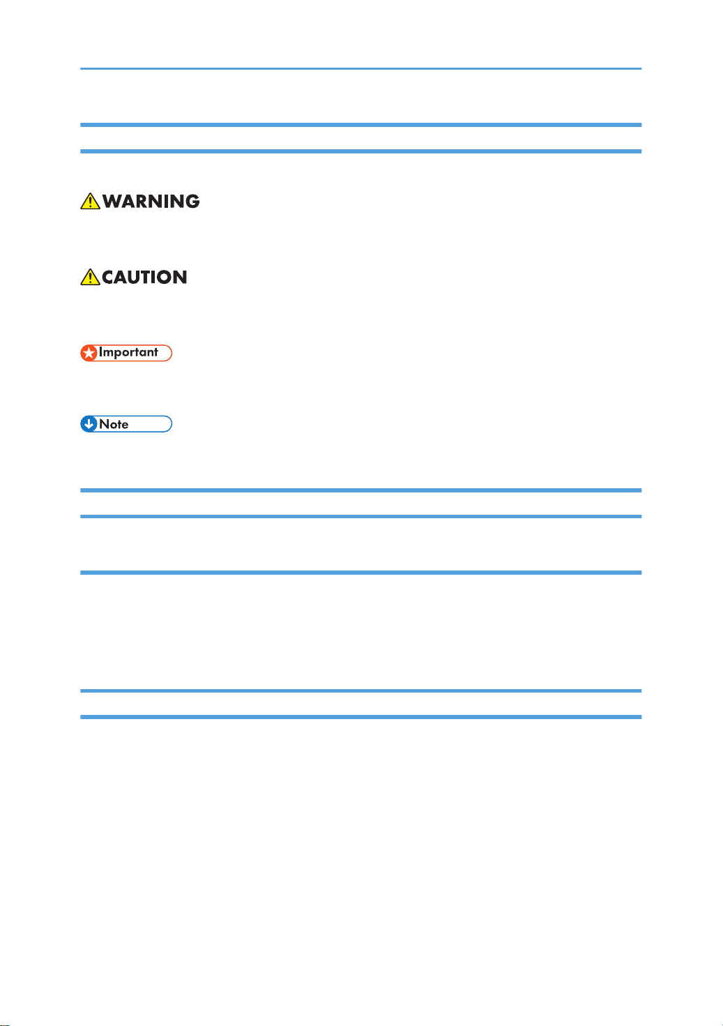
1. Disconnect the I/F cable [A] from the bridge unit ( x1).
ta-c2p2_sm_d778_00165759_eng.xml 5
2. Open the front door of the upstream unit and then remove the lock screw ( x2).
3. Remove the rear cover of the upstream unit and then remove the screw of the joint
bracket ( x1).
1. Replacement and Adjustment
6ta-c2p2_sm_d778_00165759_eng.xml
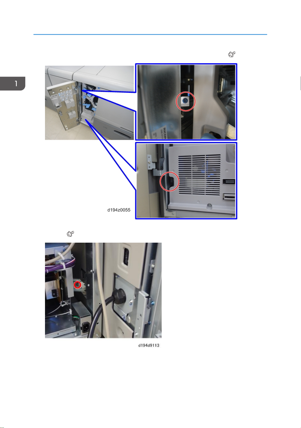
4. Detach the upstream unit [B] from the bridge unit [A] while pulling the lock bar on the
back of the lock screw (the part indicated with the blue arrow should be pulled towards
the front).
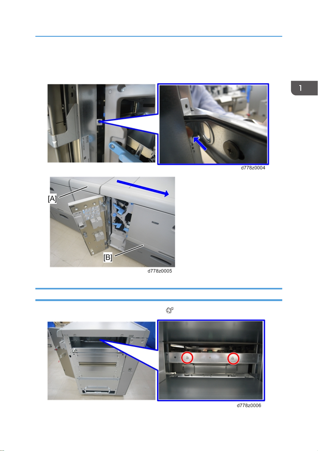
Detaching From the Downstream Unit
1. Remove the screw of the upper joint bracket ( x2).
Detaching the Bridge Unit
ta-c2p2_sm_d778_00165759_eng.xml 7
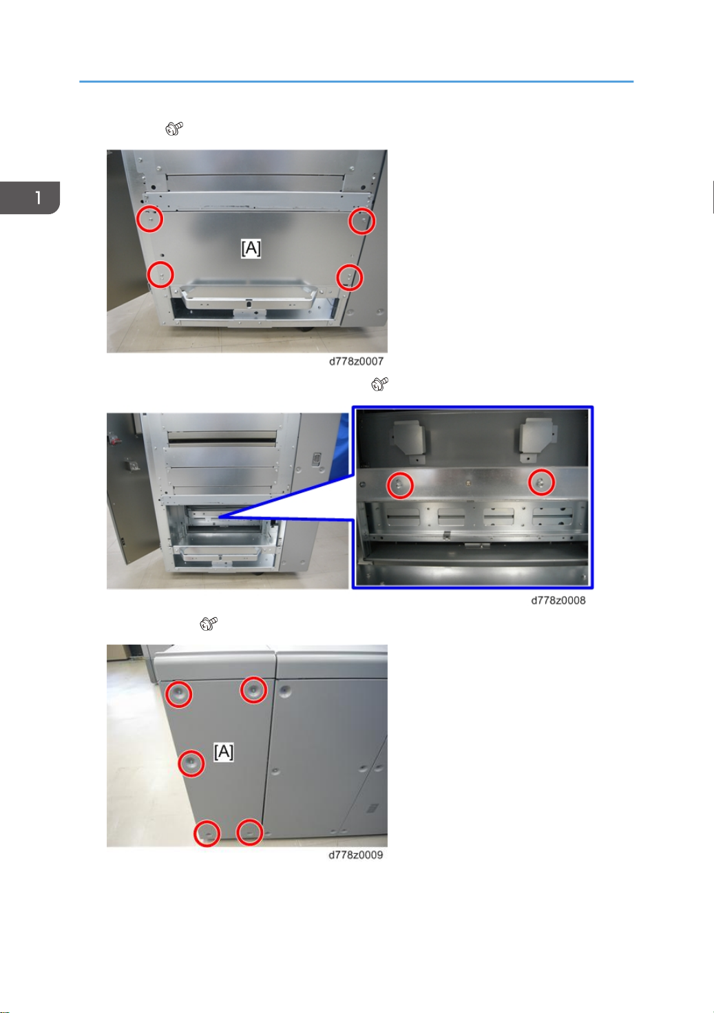
2. Plate [A] ( x4)
3. Remove the screw of the lower joint bracket ( x2).
4. Rear cover [A] ( x5)
1. Replacement and Adjustment
8ta-c2p2_sm_d778_00165759_eng.xml
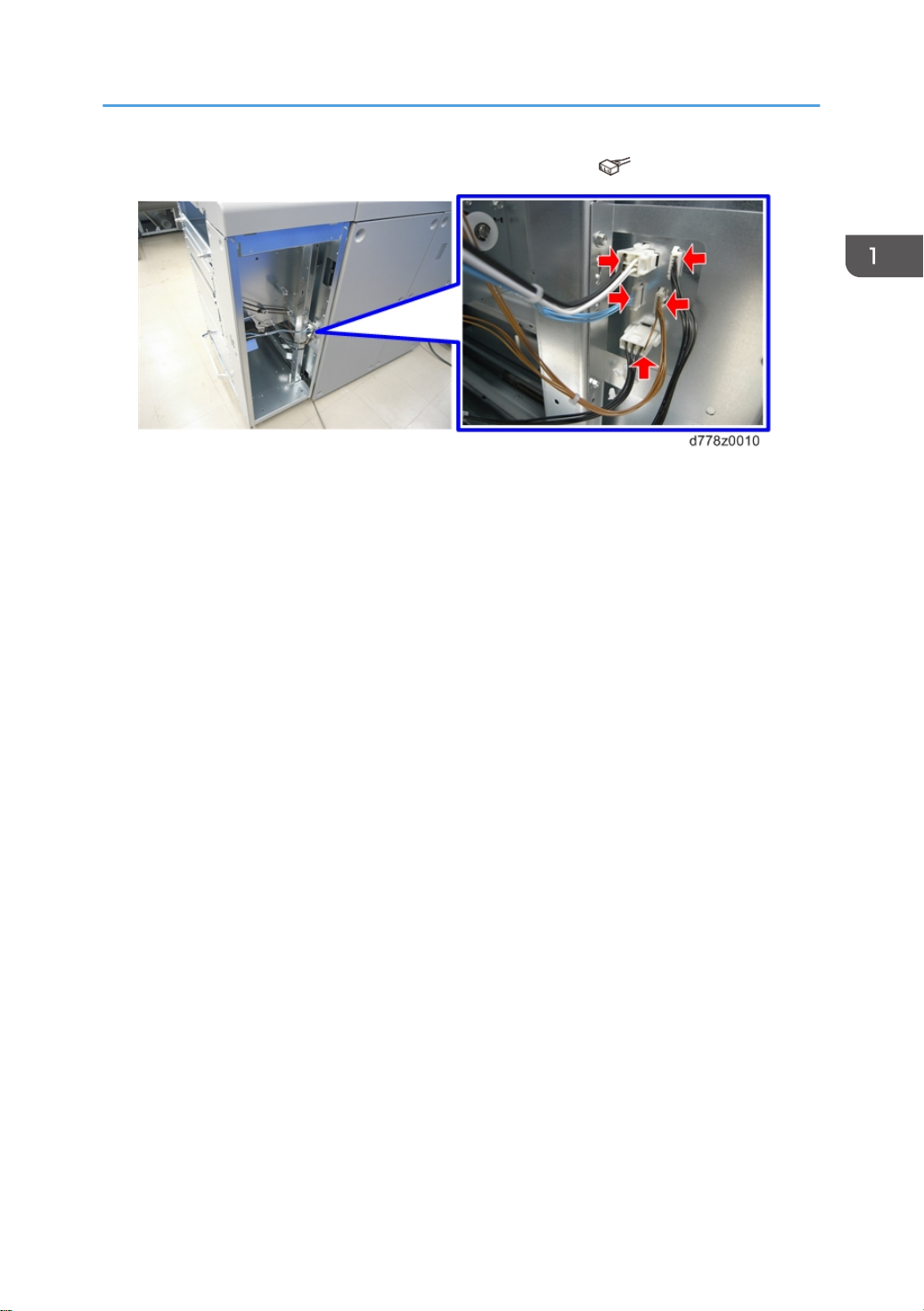
5. Disconnect all connectors connected to the downstream unit ( x5).
6. Detach the bridge unit from the downstream unit.
Detaching the Bridge Unit
ta-c2p2_sm_d778_00165759_eng.xml 9
Exterior Covers
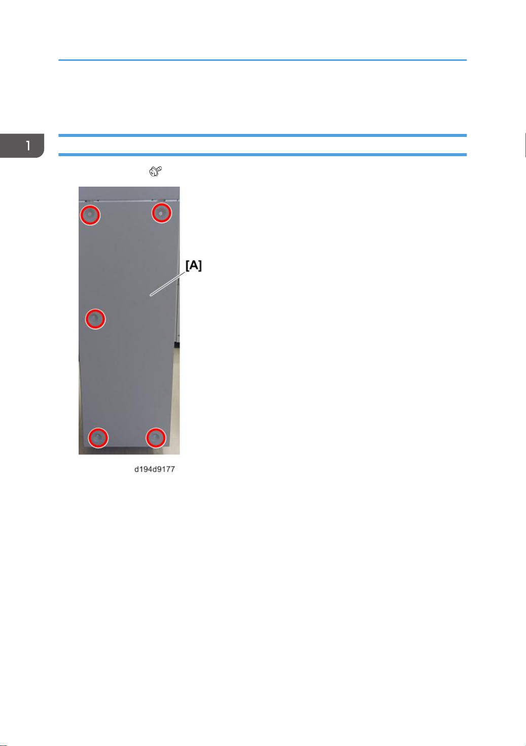
Rear Cover
1. Rear Cover [A] ( x5)
1. Replacement and Adjustment
10 ta-c2p2_sm_d778_00165762_eng.xml


3. Front corner cover [A]( x4)
Exterior Covers
ta-c2p2_sm_d778_00165762_eng.xml 13


3. LCIT Connect Motor [A]( x2)
Front Door Detection Switch
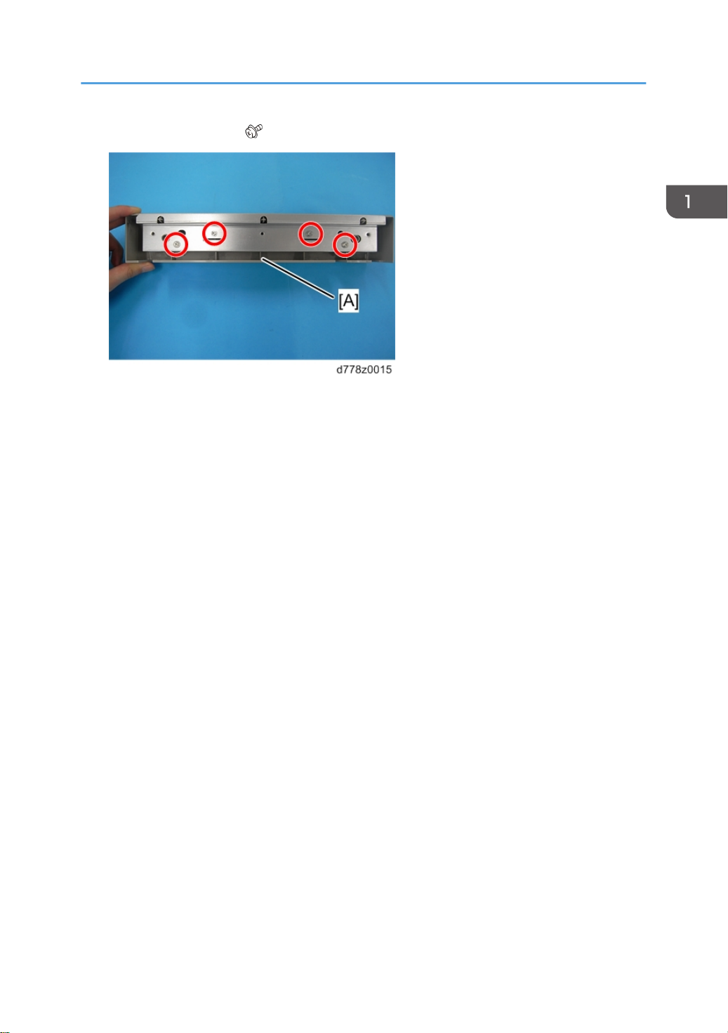
1. Open the front door.
2. Inner cover [A] ( x4)
Bridge Unit
ta-c2p2_sm_d778_00165768_eng.xml 15
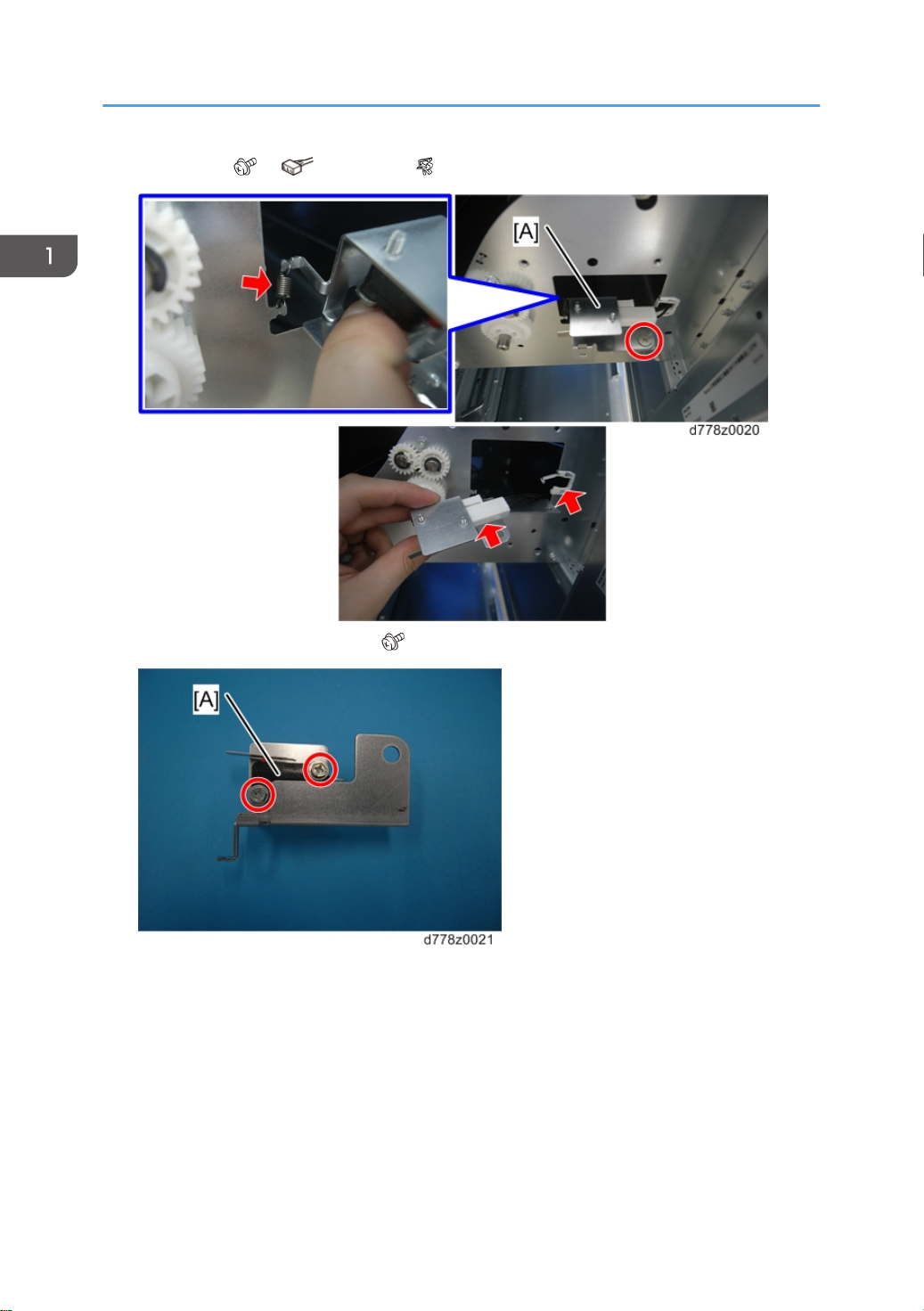
3. Bracket [A] ( x1, x1,spring x1, x1)
4. Front door detection switch [A] ( x2)
1. Replacement and Adjustment
16 ta-c2p2_sm_d778_00165768_eng.xml
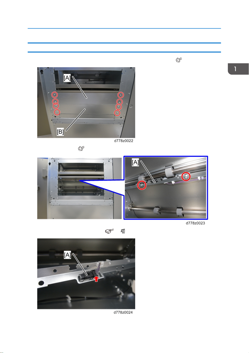
LCIT Connect Entrance Sensor
1. Remove the two plates [A] [B] from the right side of the bridge unit ( x8).
2. Sensor bracket [A] ( x2)
3. LCIT connect entrance sensor [A]( x1, x1)
Bridge Unit
ta-c2p2_sm_d778_00165768_eng.xml 17

This manual suits for next models
1
Table of contents
Other Ricoh Industrial Equipment manuals


