Ricoh SK5040 Quick start guide

High Capacity Stacker SK5040
Machine Code: D3DK
Field Service Manual
Ver 1.0
Latest Release: Feb, 2018
Initial Release: Feb, 2018
(c) 2018 Ricoh Co.,Ltd.


Symbols, Abbreviations
This manual uses several symbols and abbreviations. The meaning of those symbols and abbreviations
are as follows:
Symbol
What it means
Clip ring
Screw
Connector
Clamp
E-ring
Flat Flexible Cable
Timing Belt
SEF
Short Edge Feed
LEF
Long Edge Feed
K
Black
C
Cyan
M
Magenta
Y
Yellow
B/W, BW
Black and White
FC
Full color
[A] Short Edge Feed (SEF)
[B] Long Edge Feed (LEF)


1
Table of Contents
1. Replacement and Adjustment ............................................................................................................ 3
Common Procedures.............................................................................................................................. 3
Roll-Away Cart D456 .......................................................................................................................... 3
Covers................................................................................................................................................. 3
Jogger Unit........................................................................................................................................ 11
Straight Paper Path .............................................................................................................................. 17
Motors ............................................................................................................................................... 17
Sensors............................................................................................................................................. 18
Proof Tray............................................................................................................................................. 22
Motors ............................................................................................................................................... 22
Sensors............................................................................................................................................. 23
Shift Tray .............................................................................................................................................. 27
Paper Shift Operation ....................................................................................................................... 27
Paper Jogging................................................................................................................................... 40
Shift Tray Lift Control........................................................................................................................ 49
Shift Tray Level Adjustment.............................................................................................................. 61
Paddle Roller .................................................................................................................................... 69
Cleaning the Exit/Shift Rollers and Shafts ....................................................................................... 70
Anti-Static Brush Replacement......................................................................................................... 72
Switches, Solenoid ............................................................................................................................... 73
Door Switches................................................................................................................................... 73
Front Door Lock Solenoid................................................................................................................. 75
Fans...................................................................................................................................................... 78
Cooling Fan Motor for Paper Transport Motors ............................................................................... 78
Cooling Fan for Entrance Motor ....................................................................................................... 78
Paper Cooling Fan Motors................................................................................................................ 79
Boards .................................................................................................................................................. 85
Main Board........................................................................................................................................ 85
PSU................................................................................................................................................... 86
Operation Panel PCB ....................................................................................................................... 87
Registration Adjustment / Skew Correction.......................................................................................... 88
Skew Check...................................................................................................................................... 88
Registration Adjustment ................................................................................................................... 88
Skew Correction ............................................................................................................................... 89
2. Detailed Descriptions........................................................................................................................ 92
Overview............................................................................................................................................... 92
Main Motors ...................................................................................................................................... 92

2
Sensors............................................................................................................................................. 93
Electrical Components...................................................................................................................... 94
Paper Path........................................................................................................................................ 98
Jogger Unit........................................................................................................................................ 99
Paper Path.......................................................................................................................................... 100
Paper Path Motors.......................................................................................................................... 100
Paper Path Sensors........................................................................................................................ 101
Paper Shift and Alignment.................................................................................................................. 102
Paper Shift ...................................................................................................................................... 102
Paper Alignment: Jogging .............................................................................................................. 103
Shift Tray Lift and Height Adjustment............................................................................................. 108
Air Assistance..................................................................................................................................... 110

1.Replacement and Adjustment
3
1. Replacement and Adjustment
Common Procedures
Roll-Away Cart D456
To prevent damage to the tray switches at the back of the machine, always remove the tray
cart before moving the stacker unit.
Always remove the cart before servicing.
1. Open the front door.
2. Pull out the cart.
Covers
Rear Lower Cover, Rear Upper Cover
The rear lower cover should be removed before the rear upper cover.

1.Replacement and Adjustment
4
1. Remove the rear lower cover [A] ( x4)
2. Remove the rear upper cover [A] ( x4)
Corner Cover
1. Remove the rear lower cover and rear upper cover (see the previous section).
2. Remove the corner cover [A] ( x4).
Left Exit Cover Plate
If a peripheral unit has been installed downstream of the stacker, this cover was removed at installation.

1.Replacement and Adjustment
5
1. Remove the left exit cover plate [A] ( x2)
Left Cover
1. Remove the left exit cover plate (Left Exit Cover Plate)
2. Remove the left cover [A] ( x4)
Remove the last screw carefully. The left cover may fall suddenly because there are no hooks
holding it in place.
Never place your hand or fingers below the bottom edge of the cover when removing it.
Top Door
1. Open the top door.
2. Remove the "L" hinges [A] from the right and left ends of the door.

1.Replacement and Adjustment
7
4. Remove screws from the hinge covers [A] ( x1 each).
5. Open the front door so it is at a 90 degree angle to the unit.
6. Slide the hinge cover [A] toward you and remove it.
7. Lift the front door [A] and remove it.

1.Replacement and Adjustment
8
Front Right Cover
1. Push the front right cover [A] to the right to remove it ( x3).
Right Inner Cover
1. Remove the front right cover (Front Right Cover)
2. Remove the top door. (Top Door)
3. Remove the right inner cover [A] ( x4)
Front Left Cover
1. Remove the front door (Front Door)
2. Remove the front left cover [A] ( x3)

1.Replacement and Adjustment
9
Left Inner Cover
1. Remove the front left cover (Front Left Cover)
2. Remove the left inner cover [A] ( x5)
Proof Tray, Top Front Cover, Top Center Cover, Top Rear Cover
Remove these covers in the following order.
Proof tray [A] Top front cover [B] Top center cover [C] Top rear cover [D]
Proof Tray
1. Remove the left cover (Left Cover)
2. Remove the proof tray [A] ( x2)

1.Replacement and Adjustment
11
3. Remove the top center cover [A] ( x2)
Top Rear Cover
1. Remove the proof tray
2. Remove the top front cover
3. Remove the top center cover
4. Remove the top rear cover [A] ( x2)
Jogger Unit
Jogger Unit Removal
1. Remove the rear lower cover and rear upper cover (Rear Lower Cover, Rear Upper Cover)
2. Remove the right inner cover (Right Inner Cover)
3. Remove the left inner cover (Left Inner Cover)

1.Replacement and Adjustment
12
4. At the rear, remove three screws and disconnect five connectors ( x3, x5).
5. Remove the center plate [A] and right plate [B] ( x1 each).
6. Remove the four steel jogger unit legs.

1.Replacement and Adjustment
13
7. Remove the lock plate [A] ( x2)
8. Disconnect the jogger unit ( x3).
The jogger unit is held in place by four hooks. It will not fall after the screws have been removed.
9. Screw each leg removed in step 6 into the bottom of the jogger unit.
10. Grip one leg at the front , and one at the rear .
11. Push the jogger unit to the left to disengage the hooks.

1.Replacement and Adjustment
14
12. Slowly lower the jogger unit to the right and pull it out of the stacker.
13. Set the jogger unit on a flat surface.
Main Jogger Cover Plate
The main jogger cover plate must be removed to service these parts:
Main jogger front fence motor and HP sensor
Main jogger rear fence motor and HP sensor
Shift tray paper sensor
1. Disconnect the rear fence HP sensor harness [A] ( x1, x5).
Rear
2. Disconnect the rear fence motor harness [A] ( x1, x2).

1.Replacement and Adjustment
15
Rear
3. Disconnect the dual harness [A] for the main jogger fence retraction HP sensor and front fence HP
sensor ( x3, x6).
Front
4. Disconnect the front fence motor harness [A] ( x1, x2).
5. Remove the plate:
[A] Front ( x1)
[B] Rear ( x1)

1.Replacement and Adjustment
16
This manual suits for next models
1
Table of contents
Other Ricoh Industrial Equipment manuals
Popular Industrial Equipment manuals by other brands
ABB
ABB HT610868 Operation manual

Baileigh
Baileigh BV-6I Operator's manual

Autonics
Autonics LSC Series Communications manual
Gandy
Gandy Orbit-Air 62DS12F Parts List, Instructions
PCB Piezotronics
PCB Piezotronics PCB Load & Torque 1102-03A Installation and operating manual
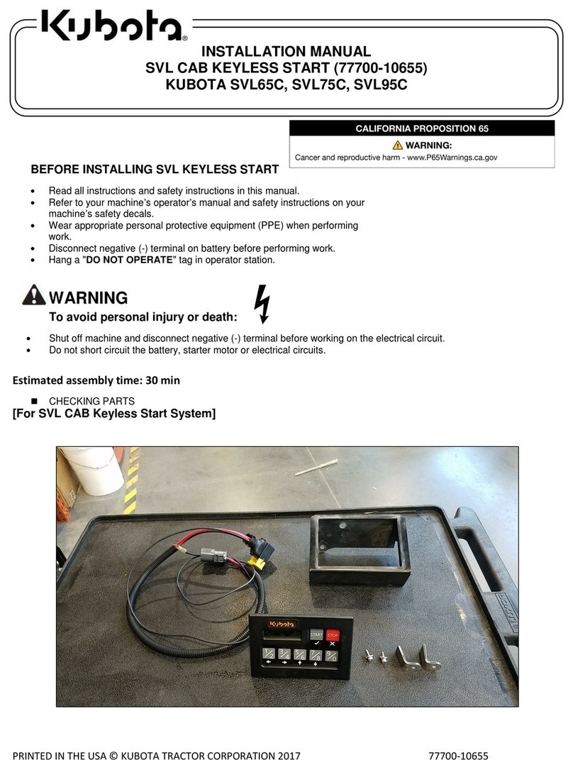
Kubota
Kubota SVL65C installation manual


