Ricoh ADF DF7010 Quick start guide

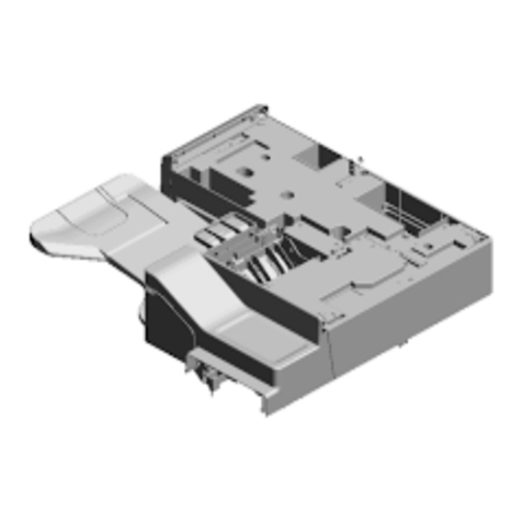
ADF DF7010
Field Service Manual
November, 2017


1
The cause of most accidents is failure to adhere to basic safety rules and observe
safety instructions. It is important to prevent potential causes of accidents from
occurring. In order to do so, read this manual carefully, and be sure to understand all
the safety instructions and correct inspection and servicing procedures that it provides
before beginning repair or servicing work.
Repairing or servicing the machine with insufcient knowledge about it could lead to
unforeseen accidents.
It is not possible to anticipate and describe in a manual such as this every possible
hazard that could arise in the course of repair and servicing. Therefore, besides
observing the safety instructions marked in this manual and on the machine's labels,
service personnel should be safety-conscious and take other safety precautions as
necessary. When performing repair or service work not covered by this manual, you
should obtain safety guidance from an appropriately knowledgeable person.
Introduction

2
Using the Service Manual
If the instructions accompanying this symbol are ignored and the
machine is operated incorrectly, death or serious injury is likely to
result.
If the instructions accompanying this symbol are ignored and the
machine is operated incorrectly, death or serious injury, or else material
damage, is likely to result.
A " " symbol tells you that a certain action is forbidden. Precisely what
is forbidden is indicated by a picture inside the symbol (in the example
here, the picture means that disassembly is forbidden), or in writing at
the side of the symbol.
A "●" symbol means that a certain action is forbidden and/or that a
specic instruction must be followed. The specic instruction is indicated
by a picture inside the symbol (in the example here, the instruction is
"Remove the power plug from the socket").
●This manual contains the following information: structure and function of major parts,
disassembly and reassembly procedures, specications, and procedures for adjustment,
maintenance, inspection and corrective action. This information is current as of September
2015, and applies basically to the model ADF DF7010. From time to time, parts are changed
to improve quality, performance or safety.
Note therefore that in some cases, certain parts or machine structure aspects described in
the text or illustrations of this manual may not be precisely the same as the product being
serviced.
●Safety instructions marked with a " " (WARNINGS and CAUTIONS) are very important for
safety and must be observed.
■ Using the Service Manual
● Safety-related instructions
● Service work-related instructions
WARNING:
CAUTION:
Examples of pictorial symbols
Draws attention to important information. If this information is ignored and
the machine is operated or serviced incorrectly, the machine's
performance could drop, or it could break down.
Draws attention to information that is useful for operation or maintenance
of the machine, and to information about its performance, etc.
IMPORTANT
REFERENCE
3
Safety Instructions
Safety Instructions
1. Cautions regarding the installation location
CAUTION
Installation environment
► Avoid installing the machine in places exposed to direct sunlight.
● Sunlight will cause the temperature in the machine's interior to rise, possibly leading to
malfunction of the control system.
● Sunlight could cause misoperation of the sensors.
● The heat of direct sunlight could cause deformation of the machine's plastic parts.
*Also avoid installation near to a ground glass window; light and heat penetrate such
windows although they are opaque.
► Avoid installing the machine in places subject to high or low temperature or humidity.
● High or low temperature or humidity could cause the machine to operate abnormally.
Suitable temperature and humidity ranges are:
Ambient temperature: 10oC-35oC
Ambient humidity: 40%-70%
Optimum temperature and humidity: 20oC, 65%
● If the machine is installed near to faucets, water heaters or humidiers, or in cool (sunless)
parts of a building or in the vicinity of water sources, the paper could absorb moisture and
curl, leading to misfeeds or poor image quality.
► Avoid installing the machine in places with open ames, or where reected heat or other
hot air currents (from stoves, etc), or cold air currents from air conditioners, etc will strike it
directly.
► Avoid installing the machine in poorly ventilated places.
► Avoid installing the machine in dusty places.
► The machine should not be tilting when it is used.
● Install the machine so that it is level.
(The machine should be level to within 5mm in the front-rear direction, and 5mm in the
lateral direction.)
► Do not install the machine on shaky, sloping or otherwise unstable surfaces.
● The machine could fall over on such surfaces, or fall off them, causing injury.

4
Safety Instructions
WARNING
● Precautions for safe servicing
● Always remove the power cord plug from the outlet before starting work.
→ Otherwise, you could get a shock or your hands/ngers could be injured.
●
However, the plug must be left connected to the outlet when performing function checks (of
individual motors, a given series of operations, or electrical circuits).
When motors are operated alone in function checks, interlocks are deactivated, so be aware
of the conditions and positions of related equipment, and take great care not to put your
hands or ngers into moving parts.
● Do not touch the rotating parts when operating the drum removal button and the paper
eject switch or while the machine is running.
→ Otherwise, your hands/ngers could get caught and crushed between the drum and
rollers.
● Working clothes
• Wear clothing that enables you to work safely.
Work clothing should be close-tting.
CAUTION
2. Cautions for maintenance, inspection and servicing
● Tools
• Use tools that are appropriate for the work.
1
2
3
4
5
6
7
8
10
HELP Mode
Others
Troubleshooting
Maintenance / Check
Standard / Adjustment
Mechanism
Description of the Operation
Introduction

1
2
3
4
5
6
7
8
10
HELP Mode
Others
Troubleshooting
Maintenance / Check
Standard / Adjustment
Mechanism
Description of the Operation
Introduction

6
Introduction...................................................... 1
■ Using the service manual............................. 2
Safety instructions ....................................... 3
Introduction
1 Specications .............................................. 8
2 Dimensions.................................................. 9
3 Part Names................................................ 10
Description of the Operation
1 Description................................................. 14
2 Sequence of Operation.............................. 15
3 Function of Parts and Circuit ..................... 18
Mechanism
1 Exterior ...................................................... 24
2 ADF Section............................................... 30
3 Electrical System....................................... 36
Standards/Adjustment
1 Mechanical System ................................... 40
2 Electrical System....................................... 42
Maintenance/Check
1
Guaranteed Periodical Maintenance Cycle
.. 48
2 Cleaning and Oiling ................................... 48
3 Periodical Maintenance Check List ........... 49
Troubleshooting
1 Troubleshooting Guide .............................. 52
2 Error Display.............................................. 54
HELP Mode
1 HELP Mode List......................................... 56
2 Overview.................................................... 57
3
HELP Mode Functions and Operation Procedures. 58
Others
1 Electrical Parts Layout and Their Functions.. 68
2 Overall Wiring Layout ................................ 70
Table of Contents
Chapter 1
Chapter 2
Chapter 3
Chapter 4
Chapter 5
Chapter 6
Chapter 8
Chapter 7

1
1 Specications ............................................ 8
2 Dimensions ................................................ 9
3 Part Names............................................... 10
1. Machine Exteriors(Paper infeed side)... 10
2. Cross Section (Structure) Surface ........ 11
IntroductionChapter 1

8
Chapter 1 1 Specications
1 Specications
Model name ADF DF7010
Document feed Automatic feed
Document type Sheets*1
Document weight 64–128 gsm
Document size MAX. : 297×432 mm
MIN. : 100×148 mm
ADF Capacity 100 sheets (64 gsm), 85 sheets (80 gsm/20 lb Bond)
Document set Document face up (printing side up)
Document set orientation Document size (A4, B5, A5): portrait placement, landscape
placement
Document size (A3, B4): portrait placement only
Document processing mode One-sided document → one-sided master making
2IN1 layout
Power supply Supplied from printer 5 VDC, 24 VDC
Weight 8Kg
Dimension 563(W) x 459(D) x 203(H)mm
Operating temperature 10–35 degrees (C) (50–95 degrees (F))
Specications are subject to change without prior notice due to continual improvements.
*1 The following types of document cannot be used :
• Documents with large le-binding holes
• Documents with staples or paper clips attached
• Documents with markedly curling ends/sides, or marked folds
• Documents with tears or rough edge
• Chemically treated documents with such as thermal paper and carbon paper, etc.
• Highly transparent documents such as OHP lm and tracing paper, etc.
• Documents which surface is slippery such as art paper and coated paper, etc.
• Documents with correction uid and glue, etc.
• Documents with smaller pieces of glued paper
Always use documents of the same size. If you load documents in different length, the
printer may not operate correctly.

1
9
Chapter 1 2 Dimensions
2 Dimensions
Unit : mm

10
Chapter 1 3 Part Names
3 Part Names
1. Machine Exteriors(Paper infeed side)
1
2
3
4
No. Name
1Document tray
2ADF cover
3ADF Rear cover
4ADF Front cover

1
11
Chapter 1 3 Part Names
2. Cross Section (Structure) Surface
3
6
7
9
10
13 14
4
15 16
8
11
12
521
No. Name
1 ADF cover switch
2 ADF cover switch 2 (for interlock)
3 ADF document sensor
4 ADF feed roller
5ADF clutch A
6 ADF paper separator unit
7Feed roller A
8ADF clutch B
9 ADF document jam sensor
10 ADF document size PCB UNIT
11 ADF document cover open/close switch
12 ADF document cover open/close switch 2 (for interlock)
13 ADF document lead edge sensor
14 Glass
15 Feed roller B
16 Ejection roller

MEMO

2
Description of the Operation
Chapter 2
1 Description............................................... 14
2 Sequence of Operation ........................... 15
(1) Document Detection............................ 15
(2)
Basic Operation for Feeding Paper to Scanner
.. 16
(3)
Operation on Continuous Master Making
. 17
3 Function of Parts and Circuit ................. 18
(1) Interlock Circuit................................. 18
(2) Document Sensors ........................... 19
(3)
ADF Stepping Motor / ADF Clutch A, B
.. 20
(4) ADF Cover Switch............................. 21
(5)
ADF Document Cover Open/Close Switch
.. 22

14
Chapter 2 1 Description
1 Description
The machine contains a scanner of the document moving type which scans images while the
document is fed. The document is illuminated with the lamps while being transferred, and the
reection in proportion to the document image darkness is imaged on the CCDs through the mirror
lens. Then the image is resoluted into picture elements and converted photoelectrically into the
level of electricity simultaneously.
The document is fed and carried by a single stepping motor. Two clutches (A and B) are used to
engage or disengage the ADF feed roller and the feed roller. The clutch is turned on only for feeding
paper to engage the scanner stepping motor with the driving system for the ADF feed roller. After
the document reaches the feed roller, clutch A is turned off and clutch B is turned on. The roller
follows the movement of the document (fed by the ejection roller).
ADF document sensor
ADF paper separator unit
Feed roller A
ADF document jam sensor
ADF document size PCB UNIT
ADF document lead edge sensor
Glass
Lamp
ADF feed roller
Mirror
Feed roller B
Ejection roller
Lens CCD
gear unit
ADF stepping Motor
ADF clutch A
ADF clutch B
Non-operator’s side

2
15
Chapter 2 2 Sequence of Operation
2 Sequence of Operation
(1) Document Detection
1. Detection of the the document
2. Detection of the front end of the document
3. Detection of the rear end of the document
4. Detection of the nish of the document
5. Detection of document jam
(1) Detection of the document
The ADF document sensor detects the document on the document receiving tray. When the
document is placed on the document receiving tray, the ADF document sensor is photointerrupted
and detects the presence of the document, which turns on the ADF stepping motor and the ADF
clutch A to feed paper.
(2) Detection of the front end of the document
The ADF document lead edge sensor detects the front end of the document before the reading
section. When the ADF document lead edge sensor is photointerrupted by the document fed with
the ADF feed roller, it detects the front end of the document.
(3) Detection of the rear end of the document
The ADF document lead edge sensor also detects the rear end of the document during master
making. When the document is fed 20 mm after the rear end is detected, the reading of the
document is nished and the ADF stepping motor runs at a slower speed than the document
reading speed to eject the document. When the document is fed approx. 20 mm after the reading
is nished, the ADF stepping motor stops.
IMPORTANT
The reading of document is terminated at the earlier time when the longitudinal length is fed
of the document size selected on the control panel or the document is fed approx.20 mm
after the rear end is detected. If master making for the document with an unspecied size is
required, select a document size on the control panel with a longer longitudinal length than the
longitudinal length of the document.
(4) Detection of the nish of the document
The document sensor also detects the nish of the document on the document receiving tray.
When the rear end of the last document on the document receiving tray have passed by the
document sensor, the sensor is photoexposed and detects the nish of the document, which
prohibits feeding the next document.
(5) Detection of document jam
When the document front end detected by the ADF document sensor cannot be detected by the
ADF document jam sensor, jam error is displayed. When the document front end that has passed
by the ADF document jam sensor cannot be detected by the ADF document lead edge sensor,
jam error is displayed.
Also when the document rear end detected by the ADF document jam sensor cannot be detected
by the ADF document lead edge sensor, jam error is displayed.

16
Chapter 2 2 Sequence of Operation
(2) Basic Operation for Feeding Paper to Scanner
Operation
(1) Paper feed 1
When the document is placed on the document
receiving tray, the ADF document sensor is
photointerrupted and detects the presence of
the document. Pressing the MASTER MAKING
key turns on the ADF stepping motor and ADF
clutch A, feeding the document.
ADF document sensor
ADF stepping motor
ADF clutch A
Document
ADF document jam sensor
ADF document lead edge sensor Document
ADF document lead edge sensor
Glass
Lamp Feed roller B Ejection roller
Document
(2) Positioning
ADF Clutch A and the ADF stepping motor
are turned off when the document is fed 16
mm after the ADF document jam sensor is
photointerrupted. This prevents the position
of the documents from deviating, which is
caused by meandering during paper feeding. If
the front end of the document does not reach
the ADF document lead edge sensor within 5
seconds after the ADF document jam sensor
is photointerrupted, DOCUMENT JAM will be
displayed.
(3) Paper feed 2
The ADF stepping motor and ADF clutch B are
turned on again and the document is fed.
(4) Reading the document
After the front end of the document is detected
at the ADF document lead edge sensor, the
document is fed several steps, and shading is
performed on approximately 2mm of the front
end of the document.

2
17
Chapter 2 2 Sequence of Operation
(3) Operation on Continuous Master Making
Operation
ADF document sensor
ADF stepping motor
ADF clutch A
1st document
2nd document
ADF document jam sensor
ADF document lead edge sensor
2nd document
1st document
2nd document
ADF document lead edge sensor
Glass
Lamp Feed roller B Ejection roller
1st document
(1) Paper feed 1 for the second document
If the ADF document sensor is photointerrupted
when the document has been ejected and
master making process is nished at the
master feeding section, it is determined that
the next document exists and the ADF stepping
motor, and the ADF clutch A is turned on to
feed the document.
(2) Positioning
When the front end of the document reaches
the ADF document lead edge sensor, the ADF
document lead edge sensor is photointerrupted
and detects the front end of the document,
which turns off the ADF stepping motor and
the ADF clutch A to hold. This method assures
stable positioning of the document.
(3) Reading the document
After the front end of the document is detected
at the ADF document lead edge sensor, the
document is fed several steps, and shading is
performed on approximately 2 mm of the front
end of the document.
IMPORTANT
● When the previous document has been
printed, the printer detaches the master
and then the drum moves to the master
attachment position to open the master
clamp. During these operations, the ADF is
in the standby status.

18
Chapter 2 3 Function of Parts and Circuit
3 Function of Parts and Circuit
Description
Circuit
(1) Interlock Circuit
Opening and closing of the ADF cover and ADF document cover is detected by the micro switch.
This unit does not work for safety unless the ADF cover and ADF document cover are closed. The
unit stops immediately when the ADF cover or ADF document cover are opened during operation.
ADF Cover Switch2
When the ADF Cover is closed : OPEN
ADF Document Cover Switch 2
When the ADF Document Cover is closed : OPEN
WhiteWhite
White
CN4-25
-26
2
1
ADF DRIVE PCB UNIT
CN4-1
-2
+24V
DRIVE PCB UNIT
Brown
Blue
1
2
31
32
25
26
When the ADF Cover is opened : CLOSE
When the ADF Document Cover is opened : CLOSE
Table of contents
Other Ricoh Printer Accessories manuals

Ricoh
Ricoh BY5020 Quick start guide

Ricoh
Ricoh LCIT RT5030 Service manual

Ricoh
Ricoh Aficio 3030 User manual

Ricoh
Ricoh Aficio CL3000 User manual

Ricoh
Ricoh M3 Quick start guide

Ricoh
Ricoh 1 Bin Tray BN1030 Quick start guide

Ricoh
Ricoh 120LDS User manual

Ricoh
Ricoh InfoPrint 75 User manual

Ricoh
Ricoh PJ Interactive Kit Type 3 User manual

Ricoh
Ricoh AP600N User manual

Ricoh
Ricoh 3800C Series User manual

Ricoh
Ricoh SH3070 Quick start guide

Ricoh
Ricoh Aficio SG 3110DN User manual

Ricoh
Ricoh SR3130 Quick start guide

Ricoh
Ricoh S7 D3DS Quick start guide

Ricoh
Ricoh ARDF DF3090 Quick start guide

Ricoh
Ricoh D109 Manual

Ricoh
Ricoh M379 User manual

Ricoh
Ricoh 140F User manual

Ricoh
Ricoh M018 Manual