manuals.online logo
Brands
  1. Home
  2. •
  3. Brands
  4. •
  5. Ricoh
  6. •
  7. Printer
  8. •
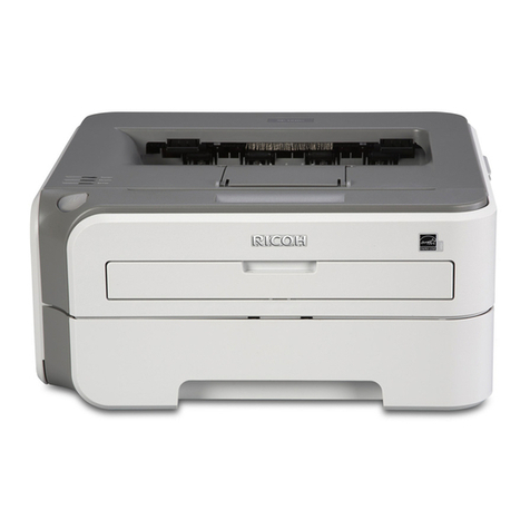
  9. Ricoh Martini-P1 Service manual

Ricoh Martini-P1 Service manual

T
echnical
B
ulletin
PAGE: 1/7
Reissued: 8-Apr-05
Model: Martini-P1 Date:
2-Mar-05 No.:
RG126001a
RTB Correction
The items in bold italics have been corrected or added.
Subject: MT-P1 Service Manual Prepared by: S. Watanabe
From: 2nd Tech Support Sec. Service Support Dept.
Classification: Troubleshooting
Mechanical
Paper path
Part information
Electrical
Transmit/receive
Action required
Service manual revision
Retrofit information
Product Safety Other ( )
AN OVERVIEW OF THE SERVICE MANUAL DIFFERENCES
BETWEEN THE MT-P1 AND MT-C1/C2
 A Service Manual will not be released for the MT-P1 (G126), so refer to this RTB and
the MT-C1/C2 Service Manual for the differences.
 The areas that are highlighted in blue are unique to the MT-P1.
 Some details are shown in other RTB/MBs.
 e.g. The Installation Procedure differences are shown in RTB RG126002.
Note: MT-P1 mass production begins from March 2005.
T
echnical
B
ulletin
PAGE: 2/7
Reissued: 8-Apr-05
Model: Martini-P1 Date:
2-Mar-05 No.:
RG126001a
1. INSTALLTION PROCEDURE
 See RTB RG126002.
2. PREVENTATIVE MAINTENANCE
 PM procedures: Same with all three models.
 PM parts: No unique parts for the P1 (see table below).
Unique/Common
C1: Common with MT-C1
C2: Common with MT-C1
C1/2: Common with MT-C1/2
Part
Number Description Q'ty/
Unit
PM
Interval
Unique or
Common
Around the drum unit
A0962057 Charge Corona Grid 1 300k C1/2
B0702364 Charge Corona Wire 1 300k C1/2
A0962063 Charge Wire Cleaning Pad 1 300k C1/2
AD041083 Cleaning Blade 1 300k C1/2
AD042038 Cleaning Brush 1 300k C1/2
AA010114 Ozone Filter (TOP) 1 300k C1/2
AA012060 Development Filter 2 300k C1/2
B0653161 Used Toner Separation
Unit 1 600k C1/2
Paper feed unit
AF031082 Feed Roller 3 1000k C1/2
AF030081 Pick-up Roller 3 1000k C1/2
AF032080 Separation Roller 4 1000k C1/2
AF031083 By-pass Feed Roller 1 1000k C1/2
AF030080 By-pass Pick-up Roller 1 1000k C1/2
Transfer belt unit
A2933899 Transfer Belt 1 450k C1/2
AD041076 Transfer Roller Cleaning
Blade 1 450k C1/2
B0653947 Discharge Plate 1 300k C1/2
T
echnical
B
ulletin
PAGE: 3/7
Reissued: 8-Apr-05
Model: Martini-P1 Date:
2-Mar-05 No.:
RG126001a
Part
Number Description Q'ty/
Unit
PM
Interval
Unique or
Common
Fusing unit
AE045046 Cleaning WEB 1 300k C1
AE040038 Cleaning WEB Pressure
Roller 1 600k C1
AE031026 Cleaning WEB Pressure
Roller Bearing 2 600k C1
AE011087 Hot Roller 1 500k C1
AE030017 Hot Roller Bearing 2 500k C1
B1104080 Stripper Pawls: Open and
Close Unit 1 300k C1
AE042052 Pressure Cleaning Roller 1 300k C1
AE031024 Pressure Cleaning Roller
Bearing 2 300k C1
AE020112 Pressure Roller 1 300k C1
AE030018 Pressure Roller Bearing 2 300K C1
Peripherals
LCT: B473
Q’ty PM
Part Number Description /Unit Interval
Unique or
Common
AF030080 Pick-up Roller 1 1000k
C1/2
AF031081 Feed Roller 1 1000k
C1/2
AF032080 Separation Roller 1 1000k
C1/2
Cover Interposer: B470
Q’ty PM
Part Number Description /Unit Interval
Unique or
Common
A8061321 Pick-up Roller 1 60k C1/2
A8061295 Feed Belt 1 60k C1/2
A8592241 Separation Roller 1 60k C1/2
T
echnical
B
ulletin
PAGE: 4/7
Reissued: 8-Apr-05
Model: Martini-P1 Date:
2-Mar-05 No.:
RG126001a
3. REPLACEMENT AND ADJUSTMENT
 Procedures: Samefor allthreemodels.
 Components: (See the table below).
Components Note
EXTERIOR
Upper Cover Unique to this model
Call Light Unique to this model
Model Name Plate Unique to this model
ELECTRICAL SECTION 1: BCU Unique to this model
ELECTRICAL SECTION 3: Controller Unique to this model
NOTE: See MB MG126001 for the P/N and illustrations for the parts above.
Components Note
EXTERIOR
Front, Side, Rear Cover Common with MT-C1/C2
LASER UNIT Common with MT-C1/C2
TANDEM TRAY Common with MT-C1/C2
UNIVERSAL TRAY Common with MT-C1/C2
BY-PASS FEED TRAY Common with MT-C1/C2
PAPER FEED UNIT Common with MT-C1/C2
LASER UNIT Common with MT-C1/C2
VERTICAL TRANSPORT Common with MT-C1/C2
PAPER REGISTRATION Common with MT-C1/C2
TONER HOPPER SECTION Common with MT-C1/C2
TONER SUPPLY Common with MT-C1/C2
DEVELOPMENT Common with MT-C1/C2
PCU Common with MT-C1/C2
TRANSFER BELT UNIT Common with MT-C1/C2
PAPER EXIT SECTION Common with MT-C1/C2
DUPLEX SECTION Common with MT-C1/C2
DRIVE SECTION Common with MT-C1/C2
TONER COLLECTION Common with MT-C1/C2
ELECTRICAL SECTION: PFC Common with MT-C1/C2
UPPER FRAME Common with MT-C1/C2
LOWER FRAME Common with MT-C1/C2
Components Note
FUSING UNIT Common with MT-C1
T
echnical
B
ulletin
PAGE: 5/7
Reissued: 8-Apr-05
Model: Martini-P1 Date:
2-Mar-05 No.:
RG126001a
4. TROUBLESHOOTING
 Same for all three models.
5. SP TABLES, ACCESS METHOD
 SP tables: Same for all three models.
 Access method:
5-1. To Enter SP Mode
Press the “Up/Down” arrow keys together for about 5 seconds, and then press the
“Enter” key.
6. DETAILED SECTION DESCRIPTIONS
 Same for all three models.
7. SPECIFICATIONS
7-1 Option Compatibility
X: Cannot be installed together
M: Must be installed together
1 2 3 4 5 6 7 8 9 10 11
1. LCT
2. LG/B4 Option M
3. Cover Interposer
4. 100 staple Finisher XXX
5. Punch unit for 4 M XXX
6. Jogger Option M X X
7. Booklet Finisher XXX
8. Punch unit for 7 and 8 XXXM
9. Copy Tray X XXX
10. DLT/A3 Tray
11. Tab sheet holder
T
echnical
B
ulletin
PAGE: 6/7
Reissued: 8-Apr-05
Model: Martini-P1 Date:
2-Mar-05 No.:
RG126001a
1. LCT
LCIT RT43 (B473: Maui)
2. LG/B4 Option
81/2"x14" Paper Size Tray Type 1075 (B474)
3. Cover Interposer
Cover Interposer Tray Type 1075 (B470)
4. 100-staple Finisher
SR841 (B706: Victoria-D)
5. Punch unit for 4
Punch Unit Type 1075 NA 3/2 (B531)
Punch Unit Type 1075 EU 2/4 (B531)
Punch Unit Type 850 SC (A812)
6. Jogger Option
Output Jogger Unit Type 1075 (B513)
7. Booklet Finisher
SR861 (B674: Zaire-Z)
8. Punch unit for 7 and 8
Punch Kit Type 1045 NA (B377)
Punch Kit Type 1045 EU (B377)
Punch Kit Type 1045 SC (B377)
9. Copy Tray
Copy Tray Type 1075 (B476)
10. DLT/A3 Tray
A3/11"x17" Tray Unit Type 1075 (B475)
11. Tab Sheet Holder
Tab Sheet Holder Type 1075 (B499)
7-2. General Specifications
Configuration Console
Paper tray, Duplex A3/11" x 17" – A5 SEF/5.5" x 8.5"
By-pass tray A3/11" x 17" – A6 SEF/5.5" x 8.5"
Print Paper Size
Non-standard
sizes
Width: 100 – 305 mm (4" x 12")
Length: 140 - 458 mm (5.5" x 18")
T
echnical
B
ulletin
PAGE: 7/7
Reissued: 8-Apr-05
Model: Martini-P1 Date:
2-Mar-05 No.:
RG126001a
Paper Tray 52.3 ~ 127.9 g/m
2
(14 ~ 34 lb.)
Duplex 64 ~ 127.9 g/m
2
(17 ~ 34 lb.)
Print Paper Weight
By-pass: Standard
Thick Paper
52.3 ~ 157 g/m
2
(14 ~ 43 lb.)
52.3 ~ 216 g/m
2
(14 ~ 58 lb.)
Printing Speed 75 ppm (A4/11" x 8.5" LEF)
First Print Time 5.5s
(1st Tray, A4/11" x 8.5" LEF)
Warm-up Time
(under 20°C room
temp.)
Less than 300s after main power is turned ON.
Tray 1
(tandem tray)
3100 sheets (80 g/m
2
, 20 lb.)
Tray 2 550 sheets (80 g/m
2
, 20 lb.)
Tray 3 550 sheets (80 g/m
2
, 20 lb.)
Paper Capacity
By-pass Tray 100 sheets (80 g/m
2
, 20 lb.)
A4/81/2" x 11" and
smaller
500 sheetsPaper Output
(Copy Tray)
B4 and larger 250 sheets
North America 120 V / 60 Hz 20 A or morePower Source
Europe/Asia 220 ~ 240 V / 50/60 Hz 10 A or
more
Allowed voltage
fluctuation
10%
North America 1.85KWPower Consumption
(Max.) Europe/Asia 1.85KW
North America 50WPower Consumption
(Energy saver) Europe/Asia 50W
Dimensions
(W x D x H)
690 x 760 x 1005 mm (27.2" x 29.9" x 39.6")*
*Without finisher and call light
690 x 760 x 1466 mm (27.2" x 29.9" x 57.7")*
*With call light
Weight Approx. 185 kg (407.8 lb.)
Resolution 1200/600/400/300 dpi
Toner Replenishment Cartridge exchange (1100 g)
Total Counter Electric Counter
T
echnical
B
ulletin
PAGE: 1/66
Reissued: 8-Apr-05
Model: Martini-P1 Date:
2-Mar-05 No.:
RG126002a
RTB Reissue
Two illustrations were corrected (pg. 10, pg. 65).
Subject: MT-P1 Installation Procedure Prepared by: S. Watanabe
From: 2nd Tech Support Sec. Service Support Dept.
Classification: Troubleshooting
Mechanical
Paper path
Part information
Electrical
Transmit/receive
Action required
Service manual revision
Retrofit information
Product Safety Other ( )
This RTB contains the Installation Procedure for the MT-P1 (G126).
Note:
 The areas that are highlighted in blue are unique to the MT-P1.
 See the MT-C1/C2 Service Manual for replacements, adjustments and other
procedures.
 Mass production for the MT-P1 begins in March 2005.
T
echnical
B
ulletin
PAGE: 2/66
Reissued: 8-Apr-05
Model: Martini-P1 Date:
2-Mar-05 No.:
RG126002a
INSTALLATION PROCEDURE
Model MT-P1
(Machine Code: G126)
T
echnical
B
ulletin
PAGE: 3/66
Reissued: 8-Apr-05
Model: Martini-P1 Date:
2-Mar-05 No.:
RG126002a
IMPORTANT SAFETY NOTICES
PREVENTION OF PHYSICAL INJURY
1. Before disassembling or assembling parts of the printer and peripherals,
make sure that the power supply cord is unplugged.
2. The wall outlet should be near the machine and easily accessible.
3. Note that some components of the machine and the paper tray unit are
supplied with electrical voltage even if the main power switch is turned off.
4. If any adjustment or operation check has to be made with exterior covers off
or open while the main switch is turned on, keep hands away from electrified
or mechanically driven components.
5. If data in before the machine completes the warm-up period, keep hands
away from the mechanical and the electrical components as the printer starts
making prints as soon as the warm-up period is completed.
6. The inside and the metal parts of the fusing unit become extremely hot while
the printer is operating. Be careful to avoid touching those components with
your bare hands.
HEALTH SAFETY CONDITIONS
1. Never operate the machine without the ozone filters installed.
2. Always replace the ozone filters with the specified ones at the specified
intervals.
3. Toner and developer are non-toxic, but if you get either of them in your eyes
by accident, it may cause temporary eye discomfort. Try to remove with eye
drops or flush with water as first aid. If unsuccessful, get medical attention.
OBSERVANCE OF ELECTRICAL SAFETY STANDARDS
1. The printer and its peripherals must be installed and maintained by a
customer service representative who has completed the training course on
those models.
2. The NVRAM on the system control board has a lithium battery which can
explode if replaced incorrectly. Replace the NVRAM only with an identical
one. The manufacturer recommends replacing the entire NVRAM. Do not
recharge or burn this battery. Used NVRAM must be handled in accordance
with local regulations.
3. The danger of explosion exists if the battery on the controller board is
incorrectly replaced. Replace the battery only with the equivalent type
recommended by the manufacturer. Discard the used controller board
battery in accordance with the manufacturers instructions and local
regulations.
T
echnical
B
ulletin
PAGE: 4/66
Reissued: 8-Apr-05
Model: Martini-P1 Date:
2-Mar-05 No.:
RG126002a
SAFETY AND ECOLOGICAL NOTES FOR DISPOSAL
1. Do not incinerate toner bottles or used toner. Toner dust may ignite suddenly
when exposed to an open flame.
2. Dispose of used toner, developer, and organic photoconductors in
accordance with local regulations. (These are non-toxic supplies.)
3. Dispose of replaced parts in accordance with local regulations.

4. When keeping used lithium batteries in order to dispose of them later, do not
put more than 100 batteries per sealed box. Storing larger numbers or not
sealing them apart may lead to chemical reactions and heat build-up.
LASER SAFETY
The Center for Devices and Radiological Health (CDRH) prohibits the repair of laser-based
optical units in the field. The optical housing unit can only be repaired in a factory or at a
location with the requisite equipment. The laser subsystem is replaceable in the field by a
qualified Customer Engineer. The laser chassis is not repairable in the field. Customer
engineers are therefore directed to return all chassis and laser subsystems to the factory
or service depot when replacement of the optical subsystem is required.
WARNING
Use of controls, or adjustment, or performance of procedures other than
those specified in this manual may result in hazardous radiation exposure.
WARNING
WARNING: Turn off the main switch before attempting any of the
procedures in the Laser Unit section. Laser beams can
seriously damage your eyes.
CAUTION MARKING:
T
echnical
B
ulletin
PAGE: 5/66
Reissued: 8-Apr-05
Model: Martini-P1 Date:
2-Mar-05 No.:
RG126002a
1. Installation Requirements
Operating Environment
1. Temperature Range: Recommended: 15°C to 25°C (59°F to 77°F)
Possible: 10°C to 32°C (50°F to 90°F)
2. Humidity Range: 15% to 80% RH (27°C 80%, 32°C 54%)
3. Ambient Illumination: Less than 1,500 lux (do not expose to direct sunlight or
strong light.)
4. Ventilation: Room air should turn over at least 3 times per hour
5. Ambient Dust: Less than 0.10 mg/m
3
6. If the place of installation is air-conditioned or heated, do not place the machine where
it will be:
1) Subjected to sudden temperature changes
2) Directly exposed to cool air from an air-conditioner
3) Directly exposed to heat from a heater
7. Do not place the machine where it will be exposed to corrosive gases.
8. Do not install the machine at any location over 2,000 m (6,500 feet) above sea level.
Humidity
10°C
(50°F)
27°C
(80.6°F)
32°C
(89.6°F)
15%
54%
80%
Temperature
Operation range
B064I502.WMF
T
echnical
B
ulletin
PAGE: 6/66
Reissued: 8-Apr-05
Model: Martini-P1 Date:
2-Mar-05 No.:
RG126002a
9. Place the printer on a strong and level base with the front and back of the machine
within ±5 mm (0.2") of level.
10. Do not place the machine where it may be subjected to strong vibrations.
11. Do not connect the machine to a power source shared with another electrical
appliance.
12. The machine can generate an electromagnetic field which could interfere with radio or
television reception.
Machine Level
1. Front to back: Within ±5 mm (0.2") of level
2. Right to left: Within ±5 mm (0.2") of level
The machine legs may be screwed up or down in order to level the machine. Set a
carpenter’s level on the upper cover.
T
echnical
B
ulletin
PAGE: 7/66
Reissued: 8-Apr-05
Model: Martini-P1 Date:
2-Mar-05 No.:
RG126002a
Minimum Space Requirements
Place the printer near the power source, providing minimum clearance as shown below.
The same amount of clearance is necessary when optional peripheral devices are installed.
Dimensions
50 mm (2") Back
700 mm (27.6") Front
40 mm (1.6") Right100 mm (4") Left
314 mm (12.4")690 mm (27.2")734 mm (28.9")
750 mm (29.5")
T
echnical
B
ulletin
PAGE: 8/66
Reissued: 8-Apr-05
Model: Martini-P1 Date:
2-Mar-05 No.:
RG126002a
Power Requirements
CAUTION
1. Make sure that the wall outlet is near the main machine and easily
accessible. Make sure the plug is firmly inserted in the outlet.
2. Avoid multi-wiring.
3. Be sure to ground the machine.
4. Never set anything on the power cord.
North America 120 V, 60 Hz: 20 A or moreInput voltage level
Europe/Asia 220 V ~ 240 V, 50 Hz/60 Hz: 10 A or more
Permissible voltage fluctuation ±10%
CAUTION
Never turn off the main power switch when the power LED is lit or flashing.
To avoid damaging the hard disk or memory, press the operation power
switch to switch the power off, wait for the power LED to go off, and then
switch the main power switch off.
• Main Power Switch.
Located on the front left corner of the machine and covered by a plastic cover. This
switch should always remain on unless the machine is being serviced.
• Rated Voltage of Output Connector
Rated Voltage of Output Connector for Accessories: Max. DC 24 V
T
echnical
B
ulletin
PAGE: 9/66
Reissued: 8-Apr-05
Model: Martini-P1 Date:
2-Mar-05 No.:
RG126002a
2. Main Machine (G126)
Accessory Check
Check the accessories and their quantities against this list:
Description Q’ty
1. Model Name Decal ( -22 Only ) ............................................ 1
2. Decal – Paper Size................................................................ 1
3. Decal: caution chart: paper Set: Direction ............................. 1
4. Decal – Toner Supply - Multiple ........................................... 1
5. Decal – D1/E1 Multiple ( -22, -27 Only ) ............................... 1
6. Stand Holder ......................................................................... 2
7. Ferrite Core (For Ethernet cable) .......................................... 1
8. Ferrite Core (For Parallel cable) ............................................ 1
9. Leveling Stopper ................................................................... 2
10. O/I Holder ............................................................................. 1
T
echnical
B
ulletin
PAGE: 10/66
Reissued: 8-Apr-05
Model: Martini-P1 Date:
2-Mar-05 No.:
RG126002a
Installation Procedure
Removing Tapes and Retainers
CAUTION
To avoid serious injury, do not connect the power plug to the machine until
you are instructed to do so.
1. Unpack the machine and remove all the wrapping.
2. Remove all filament tape from the front [A] of the machine.
3. Open the lower tray [B] and remove the operating instructions holder and foot risers.
4. Remove the data sheet [C].
5. Remove the tape from the back [D] of the machine.
NOTE: Save the filament tape and shipping retainers to prepare the machine for
shipping in the future.
G126I151.WMF
[A]
[B]
[C]
[A]
[D]
T
echnical
B
ulletin
PAGE: 11/66
Reissued: 8-Apr-05
Model: Martini-P1 Date:
2-Mar-05 No.:
RG126002a
6. Open the front door, open the toner
bottle holder [C], then remove all tape
and shipping retainers.
7. Remove the PCU inner cover [D] (2
screws) and disconnect the fan motor
[E] (1 connector).
B064I007.WMF
B064I008.WMF
[C]
[D]
[E]
T
echnical
B
ulletin
PAGE: 12/66
Reissued: 8-Apr-05
Model: Martini-P1 Date:
2-Mar-05 No.:
RG126002a
8. Lower the transfer unit by turning its
knob [A].
9. Remove the bracket [B], and the red
tag from the transfer belt (1 screw).
10. Remove the pin [C], and the red tag
from the cleaning plate.
B140I009.WMF
[A]
[B]
[C]
T
echnical
B
ulletin
PAGE: 13/66
Reissued: 8-Apr-05
Model: Martini-P1 Date:
2-Mar-05 No.:
RG126002a
11. Open the tandem tray (top paper tray)
and remove the metal retainer bracket
[D] (1 screw), wire, and red tag.
B064I401.WMF
[D]

Other Ricoh Printer manuals

Ricoh SP 6430DN User manual

Ricoh

Ricoh SP 6430DN User manual

Ricoh RCP40 User manual

Ricoh

Ricoh RCP40 User manual

Ricoh SP 150w Instruction manual

Ricoh

Ricoh SP 150w Instruction manual

Ricoh SG Series Use and care manual

Ricoh

Ricoh SG Series Use and care manual

Ricoh PostScript3 User manual

Ricoh

Ricoh PostScript3 User manual

Ricoh S-P2 User manual

Ricoh

Ricoh S-P2 User manual

Ricoh MPC6000 Installation and maintenance instructions

Ricoh

Ricoh MPC6000 Installation and maintenance instructions

Ricoh Aficio GX7000 User manual

Ricoh

Ricoh Aficio GX7000 User manual

Ricoh PRO C7200 User instructions

Ricoh

Ricoh PRO C7200 User instructions

Ricoh Aficio AP4510 User manual

Ricoh

Ricoh Aficio AP4510 User manual

Ricoh SP 8400DN User manual

Ricoh

Ricoh SP 8400DN User manual

Ricoh Aficio SP 1210N User manual

Ricoh

Ricoh Aficio SP 1210N User manual

Ricoh SP 112SU User manual

Ricoh

Ricoh SP 112SU User manual

Ricoh Aficio SP C820DN User manual

Ricoh

Ricoh Aficio SP C820DN User manual

Ricoh M047 User manual

Ricoh

Ricoh M047 User manual

Ricoh FT2050 Quick start guide

Ricoh

Ricoh FT2050 Quick start guide

Ricoh SP C240 Series Mounting instructions

Ricoh

Ricoh SP C240 Series Mounting instructions

Ricoh D124 Operating and maintenance manual

Ricoh

Ricoh D124 Operating and maintenance manual

Ricoh EMP 156 User manual

Ricoh

Ricoh EMP 156 User manual

Ricoh A183 Service manual

Ricoh

Ricoh A183 Service manual

Ricoh InfoPrint 1767 User manual

Ricoh

Ricoh InfoPrint 1767 User manual

Ricoh Pro 1107 User manual

Ricoh

Ricoh Pro 1107 User manual

Ricoh G112 User manual

Ricoh

Ricoh G112 User manual

Ricoh SP C352dn User manual

Ricoh

Ricoh SP C352dn User manual

Popular Printer manuals by other brands

Lexmark MS510 Series user guide

Lexmark

Lexmark MS510 Series user guide

Brother HL-6050 quick start guide

Brother

Brother HL-6050 quick start guide

HPRT Poooli L1 quick start guide

HPRT

HPRT Poooli L1 quick start guide

Citizen CZ-01 user guide

Citizen

Citizen CZ-01 user guide

Core Smart PT-280 user manual

Core Smart

Core Smart PT-280 user manual

Novexx Solutions ALX 73 Series operating manual

Novexx Solutions

Novexx Solutions ALX 73 Series operating manual

BIXOLON SRP-350III user manual

BIXOLON

BIXOLON SRP-350III user manual

Panasonic JT-H200PR Series operating instructions

Panasonic

Panasonic JT-H200PR Series operating instructions

Tektronix Phaser 480X user manual

Tektronix

Tektronix Phaser 480X user manual

Entrust SR200 SDK Guide

Entrust

Entrust SR200 SDK Guide

Riso VALEZUS T1200 user guide

Riso

Riso VALEZUS T1200 user guide

Sony DPP--SV77 Service manual

Sony

Sony DPP--SV77 Service manual

Sams STAR NR-10 Service data

Sams

Sams STAR NR-10 Service data

Canon SELPHY CP1500 manual

Canon

Canon SELPHY CP1500 manual

MSSC Smart-Jet BLUE user manual

MSSC

MSSC Smart-Jet BLUE user manual

Epson tm-m30 user manual

Epson

Epson tm-m30 user manual

Epson 1160 CFS installation instructions

Epson

Epson 1160 CFS installation instructions

Epson Stlyus Photo 1500W installation guide

Epson

Epson Stlyus Photo 1500W installation guide

manuals.online logo
manuals.online logoBrands
  • About & Mission
  • Contact us
  • Privacy Policy
  • Terms and Conditions

Copyright 2025 Manuals.Online. All Rights Reserved.