RIDGID K-750 User manual

K-750 Drain Cleaning
Machine
•Français– 21
• Castellano – 45
Drain Cleaner
Manual

Table of Contents
Recording Form for achine Serial Number ..............................................................................................................1
Safety Symbols ..............................................................................................................................................................2
Power Tool Safety Warnings
Work Area Safety ........................................................................................................................................................2
Electrical Safety...........................................................................................................................................................2
Personal Safety ...........................................................................................................................................................3
Tool Use and Care ......................................................................................................................................................3
Service ........................................................................................................................................................................3
Specific Safety Information
Drain Cleaner Safety ...................................................................................................................................................3
RIDGID®Contact Information........................................................................................................................................4
Description, Specifications and Standard Equipment
Description ..................................................................................................................................................................4
Specifications ..............................................................................................................................................................5
Standard Equipment....................................................................................................................................................5
achine Assembly ........................................................................................................................................................6
Connecting/Disconnecting 5/8" and 3/4" Drum Machine Cable Couplings .....................................................................7
Pre-Operation Inspection..............................................................................................................................................8
achine and Work Area Set-Up ...................................................................................................................................9
Operating Instructions ................................................................................................................................................11
Operation...................................................................................................................................................................12
Feeding The Cable Into The Drain ............................................................................................................................12
Cleaning The Drain ...................................................................................................................................................13
Working The Blockage ..............................................................................................................................................14
andling A Stuck Tool...............................................................................................................................................14
Freeing A Stuck Tool.................................................................................................................................................14
Retrieving The Cable.................................................................................................................................................14
Using Machine With A Front Guide ose..................................................................................................................15
Adding Additional Cable ............................................................................................................................................15
Drum Removal and Installation .................................................................................................................................15
aintenance Instructions ...........................................................................................................................................17
Cleaning ....................................................................................................................................................................17
Cables .......................................................................................................................................................................17
AUTOFEED...............................................................................................................................................................17
Lubrication.................................................................................................................................................................17
Front Guide ose ......................................................................................................................................................17
Accessories .................................................................................................................................................................18
achine Storage..........................................................................................................................................................18
Service and Repair ......................................................................................................................................................18
Disposal........................................................................................................................................................................18
Troubleshooting ..........................................................................................................................................................19
EC Declaration of Conformity ...........................................................................................................Inside Back Cover
Lifetime Warranty..........................................................................................................................................Back Cover
*Original Instructions - English
278-104-411.10_REV Fii
K-750 Drain Cleaning Machine

K-750 Drain Cleaning Machine
Drain Cleaner
K-750 Drain Cleaning Machine
Record Serial Number below and retain roduct serial number which is located on name late.
Serial
No.
WARNING!
Read this O erator’s Manual
carefully before using this
tool. Failure to understand
and follow the contents of
this manual may result in
electrical shock, re and/or
serious ersonal injury.

278-104-411.10_REV F2
K-750 Drain Cleaning Machine
General Power Tool Safety
Warnings*
WARNING
Read all safety warnings, instructions, illustrations
and specifications provided with this power tool.
Failure to follow all instructions listed below may re-
sult in electric shock, fire, and/or serious injury.
SAVE ALL WARNINGS AND INSTRUCTI NS
F R FUTURE REFERENCE!
The term "power tool" in the warnings refers to your mains-
operated (corded) power tool or battery-operated (cordless)
power tool.
Work Area Safety
•Keep work area clean and well lit. Cluttered or dark
areas invite accidents.
•Do not operate power tools in explosive atmo-
spheres, such as in the presence of flammable liq-
uids, gases, or dust. Power tools create sparks which
may ignite the dust or fumes.
•Keep children and by-standers away while operat-
ing a power tool. Distractions can cause you to lose
control.
Electrical Safety
•Power tool plugs must match the outlet. Never
mod ify the plug in any way. Do not use any adapter
plugs with earthed (grounded) power tools. Unmodi -
fied plugs and matching outlets will reduce risk of elec-
tric shock.
•Avoid body contact with earthed or grounded sur-
faces such as pipes, radiators, ranges and refrig-
erators. There is an increased risk of electrical shock
if your body is earthed or grounded.
•Do not expose power tools to rain or wet condi-
tions. Water entering a power tool will increase the risk
of electrical shock.
•Do not abuse the cord. Never use the cord for car-
rying, pulling or unplugging the power tool. Keep
cord away from heat, oil, sharp edges or moving
parts. Damaged or entangled cords increase the risk of
electric shock.
•When operating a power tool outdoors, use an ex-
tension cord suitable for outdoor use. Use of a
cord suitable for outdoor use reduces the risk of elec-
tric shock.
•If operating a power tool in a damp location is un-
avoidable, use a ground fault circuit interrupter
(GFCI) protected supply. Use of a GFCI reduces
the risk of electric shock.
Safety Symbols
In this operator’s manual and on the product, safety symbols and signal words are used to communicate important safety
information. This section is provided to improve understanding of these signal words and symbols.
This is the safety alert symbol. It is used to alert you to potential personal injury hazards. Obey all safety messages that follow this
symbol to avoid possible injury or death.
DANGER indicates a hazardous situation which, if not avoided, will result in death or serious injury.
WARNING indicates a hazardous situation which, if not avoided, could result in death or serious injury.
CAUTION indicates a hazardous situation which, if not avoided, could result in minor or moderate injury.
This symbol means read the operator’s manual carefully
before using the equipment to reduce the risk of injury.
The operator’s manual contains important information on
the safe and proper operation of the equipment.
This symbol means always wear safety glasses with
side shields or goggles when handling or using this
equipment to reduce the risk of eye injury.
This symbol indicates the risk of hands, fingers or other
body parts being caught, wrapped or crushed in the
drain cleaning cable.
This symbol indicates a risk of electrical shock.
This symbol indicates the risk of entanglement in a belt
and pulley.
* The text used in the General Power Tool Safety Warnings section of this manual is verbatim, as required, from the applicable UL/CSA/EN 62841-1 standard. This
section contains general safety practices for many different types of power tools. Not every precaution applies to every tool, and some do not apply to this tool.
NOTICE indicates information that relates to the protection of property.
NOTICE
DANGER
WARNING
CAUTI N

278-104-411.10_REV F 3
Personal Safety
•Stay alert, watch what you are doing and use com-
mon sense when operating a power tool. Do not
use a power tool while you are tired or under the in-
fluence of drugs, alcohol, or medication. A mo ment
of inattention while operating power tools may result in
serious personal injury.
•Use personal protective equipment. Always wear
eye protection. Protective equipment such as dust
mask, non-skid safety shoes, hard hat, or hearing pro-
tection used for appropriate conditions will reduce per-
sonal injuries.
•Prevent unintentional starting. Ensure the switch is
in the OFF position before connecting to power
source and/or battery pack, picking up or carrying
the tool. Carrying power tools with your finger on the
switch or energizing power tools that have the switch
ON invites accidents.
•Remove any adjusting key or wrench before turning
the power tool ON. A wrench or a key left attached to
a rotating part of the power tool may result in personal
injury.
•Do not overreach. Keep proper footing and balance
at all times. This enables better control of the power
tool in unexpected situations.
•Dress properly. Do not wear loose clothing or jew-
elry. Keep your hair, and clothing away from mov-
ing parts. Loose clothes, jewelry, or long hair can be
caught in moving parts.
•If devices are provided for the connection of dust
extraction and collection facilities, ensure these are
connected and properly used. Use of dust collection
can reduce dust-related hazards.
•Do not let familiarity gained from frequent use of
tools allow you to become complacent and ignore
tool safety principles. A careless action can cause se-
vere injury within a fraction of a second.
Power Tool Use and Care
•Do not force power tool. Use the correct power tool
for your application. The correct power tool will do the
job better and safer at the rate for which it is designed.
•Do not use power tool if the switch does not turn it
ON and OFF. Any power tool that cannot be controlled
with the switch is dangerous and must be repaired.
•Disconnect the plug from the power source and/or
remove the battery pack, if detachable, from the
power tool before making any adjustments, chang-
ing accessories, or storing power tools. Such pre-
K-750 Drain Cleaning Machine
ventive safety measures reduce the risk of starting
the power tool accidentally.
•Store idle power tools out of the reach of children
and do not allow persons unfamiliar with the power
tool or these instructions to operate the tool. Power
tools are dangerous in the hands of untrained users.
•aintain power tools and accessories. Check for
misalignment or binding of moving parts, breakage
of parts and any other condition that may affect the
power tool’s operation. If damaged, have the power
tool repaired before use. Many accidents are caused
by poorly maintained power tools.
•Keep cutting tools sharp and clean. Properly main-
tained cutting tools with sharp cutting edges are less
likely to bind and are easier to control.
•Use the power tool, accessories and tool bits etc. in
accordance with these instructions, taking into ac-
count the working conditions and the work to be
performed. The use of the power tool for operations dif-
ferent from those intended could result in a hazardous
situation.
•Keep handles and grasping surfaces dry, clean
and free from oil and grease. Slippery handles and
grasping surfaces do not allow for safe handling and
control of the tool in unexpected situations.
Service
•Have your power tool serviced by a qualified repair
person using only identical replacement parts.
This will ensure that the safety of the power tool is
maintained.
Specific Safety Information
WARNING
This section contains important safety informa-
tion that is specific to this tool.
Read these precautions carefully before using the
K-750 Drain Cleaning Machine to reduce the risk of
electrical shock or other serious injury.
SAVE ALL WARNINGS AND INSTRUCTI NS
F R FUTURE REFERENCE!
Keep this manual with machine for use by the operator.
Drain Cleaner Safety
•Before using the tool, test the ground fault circuit in-
terrupter (GFCI) provided with the supply cord to
insure it is operating correctly. A properly operating
GFCI reduces the risk of electrical shock.

278-104-411.10_REV F4
K-750 Drain Cleaning Machine
tion except as described in this manual. Operating in
reverse can result in cable damage and is used to
back the cable end out of blockages.
•Do not wear loose clothing or jewelry. Keep your
hair and clothing away from moving parts. Loose
clothing, jewelry or hair can be caught in moving parts.
•Do not operate this machine if operator or machine
is standing in water. Operating machine while in water
increases the risk of electrical shock.
•Do not use if there is the risk of contact with other
utilities (such as natural gas or electric) during op-
eration. Visual inspection of the drain with a camera is
a good practice. Crossbores, improperly placed utilities
and damaged drains could allow the cutter to contact
and damage the utility. This could cause electrical
shock, gas leaks, fire, explosion or other serious dam-
age or injury.
•Read and understand these instructions and the in-
structions and warnings for all equipment and ma-
terials being used before operating this tool to
reduce the risk of serious personal injury.
RIDGID®Contact Information
If you have any question concerning this RIDGID®product:
– Contact your local RIDGID®distributor.
– Visit RIDGID.com to find your local RIDGID contact
point.
– Contact Ridge Tool Technical Service Department at
Cana da call (800) 519-3456.
Description, Specifications and
Standard Equipment
Description
The RIDGID®K-750 Drain Cleaning Machine will clean
drain lines 3" to 8" in diameter and 200 feet in length de-
pending on size of cable. Corrosion resistant cable drum
holds 100 feet of 3/4" diameter cable or 125 feet of 5/8" di-
ameter cable. Cable spins at 200 RPM.
The drum is belt-driven by a 1/2P electric motor that
has a grounded electrical system. An integral Ground
Fault Interrupter (GFCI) is built into the line cord. A pneu-
matic foot switch provides ON/OFF control of the motor. A
“kickstand” base is provided for machine stability during op-
eration.
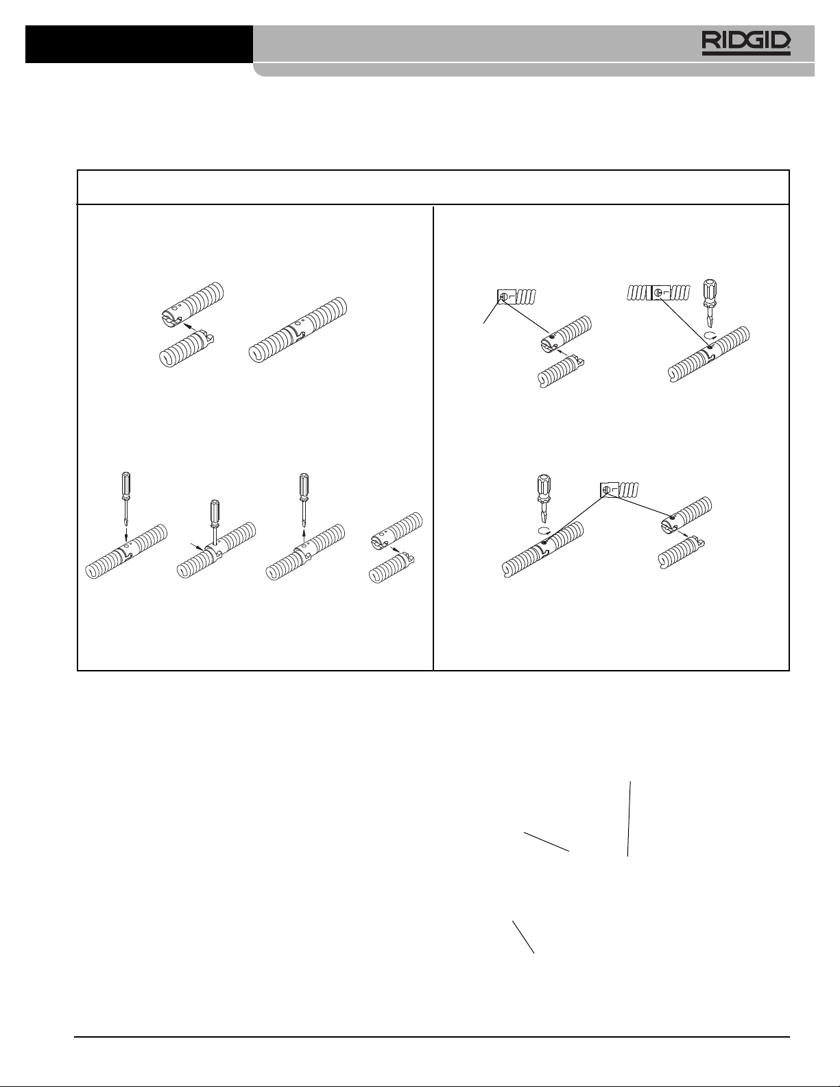
The cable has a quick change coupling system for con-
necting or disconnecting tools. An optional AUTOFEED ad-
vances or retracts the cable at a rate up to 20 feet per
minute. A manual feed option is also available.
•Only use extension cords that are protected by a
GFCI. The GFCI on the machine power cord will not
prevent electrical shock from extension cords.
•Only grasp the rotating cable with gloves recom-
mended by the manufacturer. Latex or loose fitting
gloves or rags can become wrapped around the cable
and may result in serious personal injury.
•Do not allow the cutter to stop turning while the
cable is turning. This can overstress the cable and
may cause twisting, kinking or breaking of the cable and
may result in serious personal injury.
•One person must control both the cable and the
foot switch. If the cutter stops rotating, the operator
must be able to turn the machine motor OFF to prevent
the cable from twisting, kinking and breaking.
•Use latex or rubber gloves inside the gloves rec-
ommended by the manufacturer, goggles, face
shields, protective clothing, and respirator when
chemicals, bacteria or other toxic or infectious
substances are suspected to be in a drain line.
Drains may contain chemicals, bacteria and other sub-
stances that may cause burns, be toxic or infectious or
may result in other serious personal injury.
•Practice good hygiene. Do not eat or smoke while
handling or operating the tool. After handling or op-
erating drain cleaning equipment, use hot, soapy
water to wash hands and other body parts ex-
posed to drain contents. This will help reduce the risk
of health hazards due to exposure to toxic or infectious
material.
•Only use the drain cleaner for the recommended
drain sizes. Using the wrong size drain cleaner can
lead to twisting, kinking or breaking of the cable and may
result in personal injury.
•Keep hands away from rotating drum and guide
tube. Do not reach into drum unless machine is un-
plugged. and may be caught in the moving parts.
•Keep glove-covered hand on the cable whenever
the machine is running. This provides better control of
the cable and helps prevent twisting, kinking and break-
ing of the cable and may result in serious personal in-
jury.
•Position machine cable outlet within 3' (0.9 m) of
the drain inlet or properly support exposed cable
when the distance exceeds 3' (0.9 m). Greater dis-
tances can cause control problems leading to twisting,
kinking or breaking of the cable. Twisting, kinking or
breaking cable may cause striking or crushing injuries.
•Do not operate the machine in REV (reverse) rota-

Specifications
Line Capacity ..................See Following C art.
Drum Capacity...............100' of 3/4" Cable or
125' of 5/8" Cable
Motor Type ......................Induction
Motor Rating
120V Motor ..................120VAC Single Phase
6.5 A, 60 z
220-240V Motor ...........220-240VAC
3.0 A, 50/60 z, 425W
No Load Speed ...............200 r/min (RPM)
Weight (Machine Only)...95 lbs.
Dimensions
Length..........................26"
Width............................21"
eight ..........................43"
Sound Pressure (LPA)* .......58 dB(A), K=3
Sound Power (LWA)*...........59.3 dB(A), K=3
* Sound measurements are measured in accordance with a standardized test per
Standard EN 62481-1.
- Sound emissions may vary due to your location and specific use of these
tools.
- Daily exposure levels for sound need to be evaluated for each application and
appropriate safety measures taken when needed. Evaluation of exposure lev-
els should consider the time a tool is switched off and not in use. This may sig-
nificantly reduce the exposure level over the total working period.
Figure 1 – K-750 Drain Cleaning achine with AUTOFEED
Figure 2 – achine Serial Number
The machine serial number is located on the rear drum
support. The last 4 digits indicates the month and year of
the manufacture. (MM = month, YY = year).
Standard Equipment
All K-750 Drain Cleaning Machines come with one pair of
RIDGID Drain Cleaning Gloves.
This machine is made to clean drains. If prop-
erly used it will not damage a drain that is in good condi-
tion and properly designed, constructed and maintained.
If the drain is in poor condition, or has not been properly
designed, constructed and maintained, the drain cleaning
process may not be effective or could cause damage to
the drain. The best way to determine the condition of a
278-104-411.10_REV F 5
K-750 Drain Cleaning Machine
Cable Size Recommended Line
and Type Size and Reach
Line Size Reach
5/8" Cable 3" to 6" 150'
3/4" Cable 4" to 8" 200'
Belt
Guard
AUTOFEED
Guide Tube
Loading Wheel
Handles
FOR/OFF/REV
Switch
Foot Switch
Drum
Kickstand
otor
GFCI Cord
NOTICE
XXXXXXXXMMYY

278-104-411.10_REV F6
drain before cleaning is through visual inspection with a
camera. Improper use of this drain cleaner can damage
the drain cleaner and the drain. This machine may not
clear all blockages.
Machine Assembly
WARNING
To reduce the risk of serious injury during use, follow
these procedures for proper assembly.
F R/ FF/REV switch should be FF and machine un-
plugged before assembly.
Installing Handles
1. Remove the bolts and nuts retaining the belt guard
bracket to the machine frame, remove belt guard.
2. Loosely assemble loading wheel to handles with pro-
vided bolts (see Figure 3).
Figure 3 – Handle Installation and Belt Guard Adjustment
3. Insert handles into machine frame and install bolts
through belt guard bracket, machine frame and han-
dle. Install nuts to retain bolts, do not tighten.
4. Firmly tighten bolts holding loading wheel to handles.
5. Adjust gap between guard and drum to less than
1/4". Firmly tighten belt guard bracket bolts. Confirm
that gap between belt guard and drum is less than 1/4"
to prevent fingers and other objects from being pulled
into the belt and pulley. Adjust if necessary.
Installing Cable
Do not remove the bands or cables from the cable car-
ton. The cable is under tension and can whip or strike if
released.
anual Cable Installation – this can be used for both
Manual and AUTOFEED units.
1. Retrieve male coupling end of cable through the
center hole of the carton and pull approximately 6' of
cable from the carton.
2. Connect the male coupling of the cable to the pigtail
coupling (See Figure 4). Confirm connection is se-
cure.
3. Pull short sections of cable from the carton and man-
ually feed into the drum. Do not turn machine ON.
AUTOFEED Cable Installation
1. Retrieve male coupling end of cable through center
hole of carton and pull cable from carton. Lay cable
out straight in a flat area (such as an empty paved
parking lot or driveway) with no obstructions or items
that could become wrapped around the cable.
2. When using an AUTOFEED to load cable, the rotat-
ing cable will tend to walk sideways. To prevent this,
place suitable stops (such as wood blocks) on either
side of the cable at 10 foot intervals.
3. After properly inspecting and setting up the drain
cleaner, attach the cable to the pigtail as shown in
Figure 4. Make sure that no one is in the area around
the cable. Tighten the AUTOFEED knob so that the
roller touches the cable plus one additional turn. With
the FOR/OFF/REV switch in the FOR position, press
the foot switch to start the drum turning. Move the
feed handle in the opposite direction of the cable ro-
tation to feed the cable into the drum.
4. When 10' of cable is left outside of the drum, step off
the foot switch and move the FOR/OFF/REV switch to
OFF. Loosen the AUTOFEED knob and manually
feed the remaining cable into the drum. Do not use the
AUTOFEED to put all of the cable in the drum. The
cable end can whip around and cause serious injury.
K-750 Drain Cleaning Machine
Loading Wheel
Belt Guard
Gap
1/4" AX.
Handles
Belt Guard
Fasteners

Figure 5 – Attaching Front Guide Hose To AUTOFEED
278-104-411.10_REV F 7
Attaching Front Guide Hose (Optional Accessory
For Use With AUTOFEED)
1. Pull approximately 4' of cable from the drum.
2. Slide Front Guide ose over the cable, adapter end
first. Pull plunger pin head up and place adapter over
the mounting collar on the AUTOFEED. Make sure
plunger pin locks into the hole in the mounting collar.
K-750 Drain Cleaning Machine
Connecting/Disconnecting 5/8" and 3/4" Drum Machine
Cable Couplings
Keep couplings clean and lubricated. Plunger pin must move freely and fully extend to secure connection.
New style – Plunger pin
Screwdriver required.
Connecting
1. Slide the couplings together. If needed, depress plunger
pin.
2. Confirm connection is secure. (plunger pin fully ex-
tended).
Disconnecting
1. Insert the screwdriver to depress the plunger pin.
2. Push the couplings apart until the male coupling con-
tacts the screwdriver.
3. Remove the screwdriver and push the couplings apart.
12
ld style – Rotating pin
Screwdriver required.
Connecting
1. Slide the couplings together.
2. Rotate pin so hash mark is away from end of cable (to-
wards “L” stamped on coupling). Confirm connection is
secure.
Disconnecting
1. Rotate pin so hash mark is towards end of cable (away
from “L” stamped on coupling).
2. Push the couplings apart.
13a 3b2
ash Mark
Figure 4
Plunger Pin
Hole
Guide Hose

278-104-411.10_REV F8
Pre- peration Inspection
WARNING
Before each use, inspect your drain cleaning ma-
chine and correct any problems to reduce the risk of
serious injury from electric shock, twisted or broken
cables, chemical burns, infections and other causes
and prevent drain cleaner damage.
Always wear safety glasses, RIDGID drain cleaning
gloves, and other appropriate protective equipment
when inspecting your drain cleaner. For extra pro-
tection from chemicals and bacteria on the equip-
ment, wear latex, rubber or other liquid barrier
gloves under the RIDGID drain cleaning gloves.
1. Inspect the RIDGID drain cleaning gloves or mitts
(“gloves”). Make sure they are in good condition with
no holes, tears or loose sections that could be caught
in the rotating cable. It is important not to wear im-
proper or damaged gloves. The gloves protect your
hands from the rotating cable. If the gloves are not
RIDGID drain cleaning gloves or are damaged or
worn out, do not use machine until RIDGID drain
cleaning gloves are available. See Figure 6.
Figure 6 – RIDGID Drain Cleaning Gloves – Leather, PVC
2. Make sure that the drain cleaning machine is un-
plugged and inspect the power cord, Ground Fault
Circuit Interrupter (GFCI) and plug for damage. If the
plug has been modified, is missing the grounding
prong or if the cord is damaged, to avoid electrical
shock, do not use the machine until the cord has
been replaced by a qualified repair person.
3. Clean any oil, grease or dirt from all equipment han-
dles and controls. This helps prevent the machine or
control from slipping from your grip.
4. Make sure the foot switch is attached to the drain
cleaning machine. Do not operate the machine with-
out the foot switch.
5. Inspect the drain cleaning machine for the following
items:
• Proper assembly and completeness
• Any broken, worn, missing, mis-aligned or binding
parts
• Smooth and free movement of the AUTOFEED
handle throughout range. Rotate the drum and
make sure that it turns freely without binding.
• Presence and readability of the warning label (see
Figure 7).
• Presence and proper adjustment of the belt guard.
Belt guard should be adjusted so that the gap be-
tween the guard and the drum is no more than 1/4".
(See Figure 3.)
• Any condition which may prevent safe and normal
operation.
If any problems are found, do not use the drain cleaner
until the problems have been repaired.
Figure 7 – Warning Label
6. Clean any debris from the cable and cutting tools.
Inspect cables for wear and damage. Inspect for:
• Obvious flats worn into the outside of the cable
(cable is made from round wire and the profile
should be round).
• Multiple or excessively large kinks (slight kinks up to
15 degrees can be straightened).
• Space between cable coils indicating that the cable
has been deformed by stretching, kinking, or running
in reverse (REV).
• Excessive corrosion from storing wet or exposure to
drain chemicals.
All of these forms of wear and damage weaken the
cable and make cable twisting, kinking or breaking
more likely during use. Replace worn and damaged
cable before using drain cleaner.
K-750 Drain Cleaning Machine
FORWARD
Drum
Rotation

278-104-411.10_REV F 9
Make sure the cable is fully retracted with no more
than 6" of cable outside of the machine. This will
prevent whipping of the cable at start up.
7. Inspect the tools for wear and damage. If necessary,
replace prior to using the drain cleaning machine.
Dull or damaged cutting tools can lead to binding,
cable breakage, and slow the drain cleaning process.
8. Make sure that the FOR/OFF/REV switch is set to the
OFF position.
9. With dry hands, plug cord into properly grounded out-
let. Test the GFCI provided in the electrical cord to in-
sure that it is operating correctly. When the test button
is pushed in, the indicator light should go off. Reacti-
vate by pushing the reset button in. If the indicator light
goes on, the GFCI is functioning properly. If GFCI is
not functioning properly, unplug the cord and do not
use the drain cleaning machine until the GFCI has
been repaired.
Figure 8 – Proper Drum Rotation (FOR Switch Position)
10. Move the FOR/OFF/REV switch into the FOR position.
Press the foot switch and note the direction of rotation
of the drum. If the foot switch does not control the ma-
chine operation, do not use the machine until the foot
switch has been repaired. The drum should rotate
K-750 Drain Cleaning Machine
counter-clockwise when viewed from the front of the
drum, and will match the drum direction s own on t e
warning label (Figure 7) and s own in Figure 8.
Release the foot switch and let the drum come to a
complete stop. Place the FOR/OFF/REV switch into
the REV position, and repeat above testing to confirm
that the drain cleaner operates properly in reverse. If
the rotation is not correct, do not use the machine until
it has been repaired.
11. With the inspection complete, move the FOR/OFF/ -
REV switch into the OFF position and, with dry hands,
unplug the machine.
Machine and Work Area Set-Up
WARNING
Set up the drain cleaning machine and work area ac-
cording to these procedures to reduce the risk of in-
jury from electric shock, fire, machine tipping, twist-
ed or broken cables, chemical burns, infections and
other causes, and prevent drain cleaner damage.
Always wear safety glasses, RIDGID drain cleaning
gloves, and other appropriate protective equipment
when setting up your drain cleaner. For extra pro-
tection from chemicals and bacteria on the ma-
chine and in the work area, wear latex, rubber or
other liquid barrier gloves under the RIDGID drain
cleaning gloves. Rubber soled, non-slip shoes can
help prevent slipping and electric shock, especially
on wet surfaces.
1. Check work area for:
• Adequate lighting.
• Flammable liquids, vapors or dust that may ignite.
If present, do not work in area until sources have
been identified and corrected. The drain cleaner is
not explosion proof and can cause sparks.
• Clear, level, stable dry place for machine and op-
erator. Do not use the machine while standing in wa -
ter. If needed, remove the water from the work
area. Wood or other coverings may need to be put
down.
• Properly grounded electrical outlet. A three-prong or
GFCI outlet may not be properly grounded. If in
doubt, have outlet inspected by a licensed electri-
cian.
• Clear path to electrical outlet that does not contain
any potential sources of damage for the power
cord.

278-104-411.10_REV F10
K-750 Drain Cleaning Machine
• Clear path to transport the drain cleaner to the work
area.
2. Inspect the drain to be cleaned. If possible, deter-
mine the access point(s) to the drain, the size(s) and
length(s) of the drain, distance to tanks or mainlines,
the nature of the blockage, presence of drain cleaning
chemicals or other chemicals, etc. If chemicals are pre-
sent in the drain, it is important to understand the
specific safety measures required to work around
those chemicals. Contact the chemical manufacturer
for required information.
If needed, remove fixture (water closet, etc.) to allow
access to the drain. Do not feed the cable through a
fixture. This could damage the drain cleaner and the
fixture.
3. Determine the correct drain cleaning equipment for
the application. The K-750 drain cleaner is made
for:
• 3" to 6" lines up to 150' long with 5/8" cable
• 4" to 8" lines up to 200' long with 3/4" cable
Drain cleaners for other applications can be found
by consulting the the Ridge Tool Catalog, on line
at RIDGID.com or RIDGID.eu.
Inner-Core Cable is not recommended for use through
P-Traps and severe bends in lines smaller than 4".
Optional 24" flexible trap leaders can be added to aid
users through traps and tight clean-outs.
4. Make sure machine has been properly inspected.
5. If machine is equipped with an AUTOFEED, confirm
that the AUTOFEED is set to the proper size for the
cable being used (see Figure 9). The slots in the
ends of the pins should align with the size of cable
being used. A screwdriver can be used to turn the
pins. The AUTOFEED adjustment knob may need to
be loosened to allow the size to be adjusted.
6. If needed, place protective covers in the work area.
The drain cleaning process can be messy.
Figure 9 – AUTOFEED Size Setting
7. Take the drain cleaning machine to the work area
along the clear path. If the machine needs to be
lifted, use proper lifting techniques. Use care moving
equipment up and down stairs, and be aware of pos-
sible slip hazards. Wear appropriate footwear to help
prevent slips.
8. Position the drain cleaning machine so that the K-750
cable outlet is within 3 feet of the drain access. Great -
er distances from the drain access increases the risk
of the cable twisting or kinking. If the machine cannot
be placed with the cable outlet within 3' of the drain ac-
cess, extend the drain access back to within 3' of
the cable outlet with similar sized pipe and fittings.
Improper cable support can allow the cable to kink and
twist and can damage the cable or injure the operator.
See Figure 10. If using front guide hose, place ma-
chine so that at least 6" of guide hose can be placed
in drain opening.
Figure 10 – Example of Extending Drain to Within 3' of
Cable Outlet
AUTOFEED Size Setting

278-104-411.10_REV F 11
K-750 Drain Cleaning Machine
9. Tilt the machine forward and use your foot to rotate
one kickstand at a time to the backside of the wheel.
The machine should firmly rest on the kickstands.
The kickstands stabilize the machine and help prevent
tipping or walking during use. If working on soft ground,
it may be necessary to place wood or other solid ma-
terial under the drain cleaner for proper support.
Figure 11 – Setting Kickstands
10. Evaluate the work area and determine if any barriers
are needed to keep bystanders away from the drain
cleaner and work area. The drain cleaning process can
be messy and bystanders can distract the operator.
11. Select proper tool for the conditions.
If the nature of the obstruction is unknown, it is good
practice to use a straight or bulb auger to explore the
obstruction and retrieve a piece of the obstruction for
inspection.
Once the nature of the obstruction is known, an ap-
propriate tool can be selected for the application. A
good rule of thumb is to start by running the smallest
available tool through the blockage to allow the backed
up water to start flowing and carry away the debris and
cuttings as the drain is cleaned. Once the drain is
open and flowing, other tools appropriate for the block-
age can be used. Generally, the largest tool used
should be no bigger than the inside diameter of the
drain minus one inch.
Proper tool selection depends on the specific circum-
stances of each job and is left to the users’ judgement.
A variety of other cable attachments are available and
are listed in the Accessories section of this manual.
Other information on cable attachments can be found
in the RIDGID Catalog and on line at RIDGID.com or
RIDGID.eu.
12. Securely install tool on the end of the cable (See
Figure 4). If the connection is not secure, the cutting
tool may fall off in use.
13. Position the foot switch for easy accessibility. You
must be able to hold and control the cable, control the
foot switch, and reach the FOR/OFF/REV switch.
14. Confirm that the FOR/OFF/REV switch is in the OFF
position.
15. Run the cord along the clear path. With dry hands
plug the drain cleaner into a properly grounded outlet.
Keep all connections dry and off the ground. If the
power cord is not long enough, use an extension
cord that:
• Is in good condition.
• as a three prong plug similar to that supplied on
the drain cleaner.
• Is rated for outdoor use and contains a W or W-A in
the cord designation (i.e. SOW), or complies with
05VV-F, 05RN-F types or IEC type design
(60227 IEC 53, 60245 IEC 57).
• as sufficient wire size (16 AWG (1.5mm2) for 50'
(15.2m) or less, 14 AWG (2.5mm2) for 50' – 100'
(15.2m – 30.5m) long). Undersized wires can over-
heat, melting the insulation or causing a fire or
other damage.
When using an extension cord, the GFCI on the
drain cleaner does not protect the extension cord. If
the outlet is not GFCI protected, it is advisable to use
a plug in type GFCI between the outlet and the ex-
tension cord to reduce the risk of shock if there is a
fault in the extension cord.
perating Instructions
WARNING
Always wear eye protection to protect your eyes
against dirt and other foreign objects.
Always wear RIDGID drain cleaning gloves or mitts
(“gloves”) in good condition. Latex or loose fitting
gloves or rags can become wrapped around the
cable and may result in serious personal injury.
nly wear latex or rubber gloves under drain clean-
ing gloves. Do not use damaged drain cleaning
gloves.
Always use appropriate personal protective equip-
ment while handling and using drain cleaning equip-
ment. Drains may contain chemicals, bacteria and
other substances that may be toxic, infectious,
cause burns or other issues. Appropriate personal
protective equipment always includes safety glasses
and RIDGID drain cleaning mitts, and may include

278-104-411.10_REV F12
K-750 Drain Cleaning Machine
equipment such as latex or rubber gloves, face
shields, goggles, protective clothing, respirators
and steel-toed footwear.
Do not allow the cutter to stop turning while the ma-
chine is running. This can overstress the cable and
may cause twisting, kinking or breaking of the cable.
Twisting, kinking or breaking cable may cause strik-
ing or crushing injuries.
Position machine cable outlet within 3' (0.9 m) of the
drain inlet or properly support exposed cable when
the distance exceeds 3' (0.9 m). Greater distances
can cause control problems leading to twisting,
kinking or breaking of the cable. Twisting, kinking or
breaking cable may cause striking or crushing in-
juries.
ne person must control both the cable and switch.
If the cutter stops rotating, the operator must be able
to turn the tool FF to prevent twisting, kinking
and breaking of the cable and reduce the risk of in-
jury.
Follow operating instructions to reduce the risk of
injury from twisted or broken cables, cable ends
whipping around, machine tipping, chemical burns,
infections and other causes.
1. Make sure that machine and work area is properly set
up and that the work area is free of bystanders and
other distractions.
Figure 12 – In Operating Position, anually Feeding
Cable
2. Pull cable out of drum and feed into drain. If needed,
loosen AUTOFEED knob. Push cable as far into drain
as it will go. At least one foot (.3 m) of cable must be in
drain so that the end of the cable will not come out of
the drain and whip around when the machine is
started.
Directly route the cable from the outlet of the machine
to the drain opening, minimizing exposed cable and
changes in direction. Do not tightly bend the cable –
this can increase the risk of twisting or breaking.
3. Assume a proper operating position:
• Be sure you can control the ON/OFF action of the
foot switch and can quickly release the foot switch
if needed. Do not press foot switch yet.
• Be sure that you have good balance, do not have to
over reach, and cannot fall on the foot switch, drain
cleaning machine, the drain or other hazards.
• You must be able to place at least one hand on the
cable at all times to control and support the cable.
• You must be able to reach the FOR/OFF/REV
switch.
This operating position will help to maintain control of
the cable and machine. See Figure 12.
4. Move the FOR/OFF/REV switch to the FOR (FOR-
WARD) position. Do not depress the foot switch yet.
FOR/OFF/REV refers to the drum/cable rotation and
not to the direction of cable movement. Do not rotate
the cable in reverse except as specifically described
in these instructions. Running the drain cleaner in
REV can damage the cable.
peration
The K-750 Drain Cleaning Machine is available in two
different feed configurations, either manual feed or AUTO -
FEED. A K-750 supplied with the AUTOFEED can either
feed the cable with the AUTOFEED (feed lever position) or
by manually pulling the cable from the drum and feeding it
into the drain. With the AUTOFEED you can switch back
and forth between operating methods as needed. A K-750
without the AUTOFEED can only be used manually.
Feeding The Cable Into The Drain
anual Operation
Confirm that at least one foot (.3 m) of cable is in the
drain. Grasp the exposed cable with both gloved hands
equally spaced and pull 6"-12" of cable out of the drum so
that there is a slight bow in the cable. Gloved hands must
be on the cable to control and support the cable. Improper
cable support can allow the cable to kink or twist and can
damage the cable or injure the operator. Make sure that the
cable outlet of the drain cleaner is within 3' of the drain
opening.
Depress the foot switch to start the machine. The person
controlling the cable must also control the foot switch. Do
not operate the drain cleaner with one person controlling
the cable and another person controlling the foot switch.
This can lead to twisting, kinking and breaking of the
cable. Feed the rotating cable into the drain. The rotating
cable will work its way into the drain as you push on the

278-104-411.10_REV F 13
K-750 Drain Cleaning Machine
cable with gloved hands. Do not allow the cable to build up
outside the drain, bow or curve. This can allow the cable
to twist, kink or break.
When the cable has been fed into the drain opening,
pull 6"-12" more cable from the drum and continue feed-
ing the rotating cable into the drain.
AUTOFEED Operation
Confirm that at least one foot (.3 m) of cable is in the drain.
Tighten the AUTOFEED knob (Figure13) so that the
roller touches the cable plus one additional turn. Do no
overtighten the knob – this can cause premature failure of
the AUTO FEED or cable.
Grasp near the center of the exposed length of cable with
a gloved hand. Gloved hand must be on the cable to con-
trol and support the cable. Improper cable support can
allow the cable to kink or twist and can damage the
cable or injure the operator. Make sure that the cable out-
let of the drain cleaner is within 3' of the drain opening.
Place the other hand on the AUTOFEED lever. AUT-
OFEED lever should be in neutral (Vertical) position (see
Figure 13).
See “Using Mac ine Wit A Front Guide Hose” if using
a guide ose.
Figure 13 – AUTOFEED Lever Positions
(Cable Turning In FOR Direction)
NOTE: Rate of cable advance or retrieve varies by
handle movement from neutral.
Depress the foot switch to start the machine. The person
controlling the cable must also control the foot switch. Do
not operate the drain cleaner with one person controlling
the cable and another person controlling the foot switch.
This can lead to twisting, kinking and breaking of the
cable. With the cable rotating, move the AUTOFEED
control handle in the same direction that the cable rotates.
This will cause the cable to feed out of the machine. The
further the control handle from the neutral position, the
faster the cable will be fed (up to 20' per minute, maxi-
mum). The rotating cable will work into the drain as you
control the cable with your gloved hand. Do not allow
the cable to build up outside the drain, bow or curve.
This can allow the cable to twist, kink or break.
Figure 14 – Operating the K-750 using the AUTOFEED
If it is difficult to get the cable through a trap or other fit-
ting, the following methods or combinations of meth-
ods can be used.
• Sharp thrusts of the cable, both with and without the
cable rotating, can help the cable through a trap.
• In some cases with the switch in the OFF position,
rotating the drum by hand can change the orien-
tation of the cutter to allow it to more easily ne-
gotiate the fitting.
• Run the drain cleaner in REV (REVERSE) rotation
for several seconds while pushing on the cable.
Only do this long enough to get the cable started
through the trap. Running the cable in reverse can
damage the cable.
• Use a flexible leader between the tool and the
cable.
• If these options don’t work, consider using a smaller
diameter or more flexible cable, or a different drain
cleaner.
Cleaning The Drain
As you feed the cable into the drain, you may see the
Neutral
Full
Advance
Full
Retrieve
FOR
Rotation
AUTOFEED
Knob

278-104-411.10_REV F14
K-750 Drain Cleaning Machine
cable slow down or build up outside the drain. Always
keep your hands on the cable. You may feel the cable
start to wind or load up (this may feel like the cable is start-
ing to twist or squirm). This may be a transition in the drain
(trap, elbow, etc.), build up in the drain (grease, etc.) or the
actual blockage. Feed the cable slowly and carefully. Do
not let cable build up outside the drain. This can cause the
cable to twist, kink or break.
Pay attention to the amount of cable that has been fed into
the drain. Feeding cable into a larger drain, septic tank or
similar transition may cause the cable to kink or knot
and prevent removal from the drain. Minimize the amount
of cable fed into the transition to prevent problems. Each
wrap of the cable in the drum is approximately four feet
long. If using 5/8" cable with a 3/4" pigtail, do not feed the
connection through the AUTOFEED. This could damage
the AUTOFEED.
If an additional length of cable is needed, see t e section
“Adding Additional Cable”.
Working The Blockage
If the end of the cable stops turning, it is no longer clean-
ing the drain. If the end of the cable becomes lodged in the
blockage and power is maintained to the drain cleaner, the
cable will start to wind up (this may feel like the cable is
starting to twist or squirm). aving a hand on the cable al-
lows you to feel this wind up and control the cable. If the
cable end stops turning or if the cable starts to wind up, im-
mediately pull the cable back from the obstruction:
•anual Operation – pull back on the cable to free
the cable end from the blockage.
•AUTOFEED Operation – move the feed lever in the
direction opposite the cable rotation to free the cable
end from the blockage.
Don’t keep the cable rotating if the cable is stuck in a
blockage. If the cable end stops turning and the drum
keeps rotating, the cable can twist kink or break.
Once the cable end is free of the blockage and turning
again, you can slowly feed the cable end back into the
blockage. Do not try to force the cable end through the
blockage. Let the spinning end “dwell” in the blockage to
completely break it up. Work the tool in this manner until
you have moved completely past the blockage (or block-
ages) and the drain is flowing. Manual operation is usually
the best choice if the cable repeatedly gets stuck when
using the AUTOFEED. If using an AUTOFEED machine
manually, the feed knob may need to be loosened, and
the feed lever placed in the neutral position.
While working the blockage, the cable and tool may be-
come clogged with debris and cuttings from the blockage.
This can prevent further progress. The cable and tool
need to be retrieved from the drain and the debris re-
moved. See section on “Retrieving t e Cable”.
Handling A Stuck Tool
If the tool stops turning and the cable cannot be pulled
back from the blockage, immediately release the foot
switch while firmly holding the cable. Do not remove
hands from cable or cable may kink, twist and break.
The motor will stop and the cable and drum may turn
backwards until the energy stored in the cable is re-
lieved. Do not remove hands from cable until the tension
is released. Place FOR/OFF/REV switch in OFF position.
Freeing A Stuck Tool
If the tool is stuck in the blockage, with the FOR/OFF/REV
switch in the OFF position and the foot switch released, try
pulling the cable loose from the blockage. If the tool will
not come free from the blockage, place the
FOR/OFF/REV switch in the REV position. Grasp the
cable with both gloved hands, press the foot switch for
several seconds and pull on the cable until it is free of the
blockage. Do not operate the machine in the REV position
any longer than required to free the cutting tool from the
blockage or cable damage can occur. Place the
FOR/OFF/REV switch in the FOR position and continue
cleaning the drain.
Retrieving The Cable
Once the drain is open, start a flow of water down the
drain to flush the debris out of the line. This can be done
by running a hose down the drain opening, turning on a
faucet in the system or other methods. Pay attention to the
water level, as the drain could plug again.
With water flowing through the drain, retrieve the cable
from the line. The flow of water will help to clean the
cable as it is retrieved. The FOR/OFF/REV switch should
be in the FOR position – do not retrieve the cable with the
switch in the REV position, this can damage the cable. As
with feeding the cable into the drain, cables can be
caught while being retrieved.
•anual Operation – With both gloved hands equally
spaced on the exposed cable for control, pull 6"-12"
lengths of cable from the drain at a time and feed it
into the drum .
•AUTOFEED Operation – With one hand near the
center of the exposed length of cable, move the feed
lever in the direction opposite the cable rotation to
retrieve the cable. The rotating cable will work its way
out of the drain and back into the drum.
Continue retrieving cable until the cable end is just inside
the drain opening. Release the foot switch and allow the
machine to come to a complete stop. Do not pull the

278-104-411.10_REV F 15
K-750 Drain Cleaning Machine
end of the cable from the drain while the cable is rotating.
The cable can whip around and cause serious injury.
Pay attention to the cable during retrieval as the cable end
can still become stuck.
Place the FOR/OFF/REV switch in the OFF position.
Pull the remaining cable from the drain with gloved hands
and feed back into the drain cleaner. If needed, change
the tool and continue cleaning following the above pro-
cess. Several passes through a line are recommended for
complete cleaning.
Using Machine With A Front Guide Hose
The front guide hose is an optional accessory to help
protect fixtures and contain the liquid and debris thrown
off of the cable. It can only be used with an AUTOFEED.
Using the Front Guide hose can decrease feedback
from the cable, making it harder to tell what conditions
the cable is encountering. This may increase the pos-
sibility of damage to the cable. Using the front guide
hose makes it more difficult to switch back a forth be-
tween manual and AUTOFEED operation.
Using a machine with the front guide hose is similar to
using a machine with just the AUTOFEED. Follow in-
structions for AUTOFEED operation with the following
exceptions:
• When setting up the machine, insert the guide hose at
least 6" into the drain.
Figure 15 – Using achine with Guide Hose
• Instead of holding the cable, hold the guide hose. See
Figure 15. Always control the guide hose and properly
support the cable to prevent the cable from twisting,
kinking or breaking.
When using a front guide hose, pay attention how the
guide hose feels in your hand and watch the drum ro-
tation. Because the guide hose is over the cable, there
is less sensitivity to the loading of the cable, and it is
harder to tell if the tool is rotating or not. If the tool is not
rotating, the drain is not being cleaned.
If the tool continues to get hung up in the blockage,
stop using the AUTOFEED (leave the feed lever in the
neutral position) and work the cable manually. To do this,
the cable must be retrieved from the drain and the guide
hose removed to allow proper positioning of the machine
to the drain and access to the cable. Do not try to work the
cable by hand with the front guide hose in place.
When retrieving the cable, be sure to stop the cable
before the tool is pulled into the end of the guide hose to
prevent damage.
Adding Additional Cable
If more cable is necessary to clean the drain than is avail-
able in the machine drum, use the following procedures to
add additional cable.
1. Make sure that the FOR/OFF/REV switch is in the
OFF position and the machine is unplugged.
2. Pull the cable connection from the drum. If using the
AUTOFEED, the feed knob may need to be loos-
ened.
3. Disconnect the cable from the pigtail and secure the
cable so it cannot slip down the drain.
4. If loading another cable in the existing drum, see
“Installing Cable” in the Assembly section.
5. Make sure that the drain cleaning machine is properly
set up. Attach the end of the cable in the drain to the
cable in the drum. Feed any excess cable back into
the drum.
6. Resume cleaning the drain. Make sure that the cable
is rotating and up to speed before feeding cable in.
Drum Removal and Installation
1. Make sure that the FOR/OFF/REV switch is in the
OFF position and the machine is unplugged.
2. If needed, remove AUTOFEED from machine by un-
screwing mounting bolt with 3/4" wrench. Bolt and
AUTOFEED will come off as one. See Figure 16.

278-104-411.10_REV F16
K-750 Drain Cleaning Machine
Figure 16 – Removing AUTOFEED
3. Push down on motor table to release belt tension
and slip belt off of the drum. See Figure 17.
Figure 17 – Releasing Belt Tension
4. Use 3/4" wrench to remove the bolt that holds the
drum to the machine frame. See Figure 18.
Figure 18 – Removing Drum Bolt
5. Lay machine on it’s back (see Figure 19). Use proper
lifting technique to lift the drum off of its mounting po-
sition. A drum with 100' of cable can weigh as much
as 150 pounds. In some cases, two people will be
needed to handle a drum of cable.
Figure 19 – Removing Drum
Push Down
otor Table

278-104-411.10_REV F 17
K-750 Drain Cleaning Machine
5/8" (16mm)
3/4" (20mm)
Catalog Model
No. No. Descri tion
43637 A-7558 Drum Assembly w/5⁄8" Pigtail
41982 A-7534 Drum Assembly w/3⁄4" Pigtail
43642 A-75 AUTOFEED Assembly
41992 C-100IC Kit w/Tools, 3⁄4" x 100'
49032 Front Guide ose Assembly
46015 E-453 Allen Wrench
41937 — RIDGID Leather Drain Cleaning Gloves
70032 — RIDGID PVC Drain Cleaning Gloves
59360 A-3 Tool Box
59987 Cable Rust Inhibitor 1 GAL.
31487 A-7570 5⁄8" Repair Splicer
92805 A-6582 5⁄8" Male Coupling
92810 A-6583 5⁄8" Female Coupling
31492 A-7571 3⁄4" Repair Splicer
92880 B-6840 3⁄4" Male Coupling
92885 B-6841 3⁄4" Female Coupling
Accessories
Inner Core (IC) Cables
Good flexibility and more cleaning power to the cable end.
Catalog odel
No. No. Description
92460 C-25 25' IC Cable (7.6m)
92465 C-26 50' IC Cable (15.2m)
92470 C-27 75' IC Cable (22.9m)
43647 C-24 100' IC Cable (30.5m)
92475 C-28 25' IC Cable (7.6m)
92480 C-29 50' IC Cable (15,2m)
41212 C-75 75' IC Cable (22.9m)
41697 C-100 100' IC Cable (30.5m)
5/8" (16mm)
3/4" (20mm)
Catalog odel
No. No. Description
32737 C-27 C 75' C Cable (22.9m)
58192 C-24 C 100' C Cable (30.5m)
47427 C-75 C 75' C Cable (22.9m)
47432 C-100 C 100' C Cable (30.5m)
Hollow Core Cables
Catalog odel
No. No. Description
92555 T-458 5⁄8" x 2' Leader
92560 T-468 3⁄4" x 2' Leader
44122 — 5⁄8" Pigtail, 41⁄2" Long
44117 — 3⁄4" Pigtail, 6" Long
Leaders and Pig Tails
6. Reverse steps 2-5 to reassemble a drum to the K-750
frame. Exercise care when standing the machine
up to tighten the drum bolt.
Maintenance Instructions
WARNING
F R/ FF/REV switch should be FF and machine
unplugged before performing any maintenance.
Always wear safety glasses and RIDGID drain clean -
ing gloves and other appropriate protective equip-
ment when performing any maintenance.
Cleaning
The machine should be cleaned as needed with hot,
soapy water and/or disinfectants. Do not allow water to
enter motor or other electrical components. Make sure
unit is completely dry before plugging in and using.
Cables
Cables should be thoroughly flushed with water after
every use to prevent damaging effects of sediment and
drain cleaning compounds. Flush cable with water and
drain debris from drum by tipping machine forward after
every use to remove sediment, etc. which can corrode
cable.
To help prevent corrosion during storage, cables can be
coated with RIDGID Cable Rust Inhibitor. Once the cable
is clean and dry, pull the cable from the drum. While
manually feeding the cable back into the drum, wipe the
Cable Rust Inhibitor on the cable with a cloth.
Do not apply the Cable Rust Inhibitor to a rotating
cable. The cloth and your hand can become entangled in
the cable, and Cable Rust Inhibitor can be slung from ro-
tating cable.
AUT FEED
After each use, hose out AUTOFEED assembly with
water and lubricate with lightweight machine oil.
Lubrication
Lubricate motor as per instructions on motor.
Lubricate machine with general purpose grease at
grease fitting (located at connection of guide tube and
drum) If drum is changed or removed, once a week if
used every day: once a month if used less.
Front Guide Hose
After use, flush the guide hose with water and drain.
When dry, a small amount of Cable Rust Inhibitor can be
placed in the guide hose to help keep it flexible.
Accessories
WARNING
To reduce the risk of serious injury, only use ac-
cessories specifically designed and recommended
for use with the RIDGID K-750 Drain Cleaning Ma -
chine, such as those listed below. ther Ac ces -
sories suitable for use with other tools may be
hazardous when used with the K-750 Drain Clean -
ing Machine.

278-104-411.10_REV F18
K-750 Drain Cleaning Machine
Machine Storage
The drain cleaner and cables must be
kept dry and indoors or well covered if kept outdoors.
Store the machine in a locked area that is out of reach of
children and people unfamiliar with drain cleaners. This
machine can cause serious injury in the hands of un-
trained users.
Service and Repair
WARNING
Improper service or repair can make machine un-
safe to operate.
The “Maintenance Instructions” will take care of most of
the service needs of this machine. Any problems not ad-
dressed by this section should only be handled by an au-
thorized RIDGID service technician.
Tool should be taken to a RIDGID Authorized
Independent Service Center or returned to the factory.
For information on your nearest RIDGID Authorized
Independent Service Center or any service or repair
questions:
• Contact your local RIDGID distributor.
• Visit RIDGID.com to find your local RIDGID contact
point.
• Contact Ridge Tool Technical Services Department at
Canada call (800) 519-3456
Disposal
Parts of the K-750 drain cleaner contain valuable materi-
als and can be recycled. There are companies that spe-
cialize in recycling that may be found locally. Dispose of
the com ponents in compliance with all applicable regula-
tions. Contact your local waste management authority
for more information.
For EC Countries: Do not dispose of elec-
trical equipment with household waste!
According to the European Guideline 2002/ -
96/ EC for Waste Electrical and Electronic
Equip ment and its implemen tation into nation -
al le g is lation, electrical equipment that is no
longer usable must be collected separately and disposed
of in an environmentally correct manner.
WARNING
Tools and Replacement Blades – Fits 5/8" and 3/4"
Cables
Fits C-24, C-25, C-26, C-27, C-28, C-29, C-75, C-100, C-27 C,
C-24 C, C-75 C, and C-100 C
Catalog odel
No. No.
92485 T-403
92490 T-404
92495 T-406
92500 T-407
92505 T-408
51762 T-409
92510 T-411
92515 T-412
92520 T-413
92525 T-414
92530 T-416
92535 T-432
92540 T-433
92545 T-434
92550 T-436
Blade(s)
92835
92840
92850
—
92890
—
92815
92820
92825
92830
92855
92860
92865
92870
92875
Holder
92900
92900
92915
—
92915
—
92905
92905
92910
92910
92910
92895
92895
92895
92895
Description
P-Trap Cutter, 3"
P-Trap Cutter, 31/2"
Spear Blade, 13/4"
Retrieving Auger, 29/16"
Sawtooth Cutter, 3"
-D Bulb Auger, 13/4"
Double Cutter, 2"
Double Cutter, 21/2"
Double Cutter, 3"
Double Cutter, 4"
Double Cutter, 6"
3-Blade Cutter, 2"
3-Blade Cutter, 3"
3-Blade Cutter, 4"
3-Blade Cutter, 6"
Replacement
Other manuals for K-750
4
Table of contents
Languages:
Other RIDGID Cleaning Equipment manuals

RIDGID
RIDGID K-39 User manual

RIDGID
RIDGID K-45AF-1 User manual

RIDGID
RIDGID K-750 User manual

RIDGID
RIDGID FlexShaft K9-306 User manual

RIDGID
RIDGID K-750 User manual

RIDGID
RIDGID Kollmann K-1500G User manual

RIDGID
RIDGID K-45AF-7 User manual

RIDGID
RIDGID 37343 User manual

RIDGID
RIDGID K-750R User manual

RIDGID
RIDGID K-375 User manual

RIDGID
RIDGID K-45AF-5 User manual

RIDGID
RIDGID WD1245 User manual

RIDGID
RIDGID K-45-5 User manual

RIDGID
RIDGID 60062R User manual

RIDGID
RIDGID K-400 User manual

RIDGID
RIDGID K-380 User manual

RIDGID
RIDGID 0095691373434 User manual

RIDGID
RIDGID K-45 User manual

RIDGID
RIDGID K50-100V User manual

RIDGID
RIDGID Auto-Clean K-30 User manual