RIDGID ProPress Series User manual

Pressing Tools
for Use With:
ProPress® Fitting System
ProPress® XL Fitting System
ProPress®XL–C Fitting System
•Français – 19
•Castellano – pág. 39
WARNING!
Read this Operator’s Manual
carefully before using this tool.
Failure to understand and fol-
low the contents of this manual
may result in extensive prop-
erty damage and/or serious
personal injury.
ProPress®Fitting System
Operator’s Manual

Ridge Tool Companyii
Table of Contents
Safety Symbols..............................................................................................................................................................1
General Safety Information
Work Area Safety........................................................................................................................................................1
Electrical Safety ..........................................................................................................................................................1
Personal Safety ..........................................................................................................................................................2
Tool Use and Care......................................................................................................................................................2
Service........................................................................................................................................................................2
Specific Safety Information
Pressing Tool Safety ..................................................................................................................................................2
Description and Specifications
Description..................................................................................................................................................................3
Specifications..............................................................................................................................................................3
Inspecting the Press Tool and Attachments ..............................................................................................................5
Tool and Work Area Set-Up
Mounting Attachment Into Press Tool ........................................................................................................................6
Calibrating The Pressing Tool For The Specific Pressing Attachment (320-E Pressing Tool Only) ..........................6
Calibrating The 320-E With A Jaw Set........................................................................................................................6
Calibrating The 320-E With The R2 Actuator (For Use With ProPress XL Rings) ........................................................7
Calibrating The 320-E With The V1 Or V2 Actuator (For Use With ProPress Rings Or ProPress XL-C Rings) ........7
Preparing The Connection
Preparing the Tube ....................................................................................................................................................8
Inserting the Tube Into the Fitting ..............................................................................................................................8
Operating Instructions
Pressing the Connection with a Ring and Actuator ..................................................................................................10
Inspecting the Press Connection ..............................................................................................................................11
Maintenance Instructions ..........................................................................................................................................12
Accessories
ProPress System For Copper Tubing ......................................................................................................................12
Maintenance Storage ..................................................................................................................................................13
Service and Repair......................................................................................................................................................13
Clearance Requirements ......................................................................................................................................14-17
Troubleshooting..........................................................................................................................................................18
Lifetime Warranty ........................................................................................................................................Back Cover
ProPress®Fitting System

Ridge Tool Company 1
ProPress®Fitting System
General Safety Rules*
WARNING
Read all safety warnings and all instructions. Failure to
follow the warnings and instructions may result in electric
shock, fire and/or serious injury.
SAVE ALL WARNINGS AND INSTRUCTIONS
FOR FUTURE REFERENCE!
The term "power tool" in the warnings refers to your
mains-operated (corded) power tool or battery-operated
(cordless) power tool.
Work Area Safety
•Keep your work area clean and well lit. Cluttered or
dark areas invite accidents.
•Do not operate power tools in explosive atmo-
spheres, such as in the presence of flammable
liquids, gases, or dust. Power tools create sparks
which may ignite the dust or fumes.
•Keep children and by-standers away while oper-
ating a power tool. Distractions can cause you to lose
control.
Electrical Safety
•Power tool plugs must match the outlet. Never
modify the plug in any way. Do not use any adap-
ter plugs with earthed (grounded) power tools.
Unmodified plugs and matching outlets will reduce
risk of electric shock.
•Avoid body contact with earthed or grounded sur-
faces such as pipes, radiators, ranges and refrig-
erators. There is an increased risk of electrical shock
if your body is earthed or grounded.
•Do not expose power tools to rain or wet condi-
tions. Water entering a power tool will increase the risk
of electrical shock.
•Do not abuse the cord. Never use the cord for
carrying, pulling or unplugging the power tool.
Keep cord away from heat, oil, sharp edges or
moving parts. Damaged or entangled cords increase
the risk of electric shock.
•When operating a power tool outdoors, use an
extension cord suitable for outdoor use. Use of a
cord suitable for outdoor use reduces the risk of elec-
tric shock.
•If operating a power tool in a damp location is
unavoidable, use ground fault circuit interrupter
(GFCI) protected supply. Use of an GFCI reduces the
risk of electric shock.
Personal Safety
•Stay alert, watch what you are doing and use com-
Safety Symbols
In this operator’s manual and on the product, safety symbols and signal words are used to communicate important safe-
ty information. This section is provided to improve understanding of these signal words and symbols.
This is the safety alert symbol. It is used to alert you to potential personal injury hazards. Obey all safety messages that follow this
symbol to avoid possible injury or death.
DANGER indicates a hazardous situation which, if not avoided, will result in death or serious injury.
WARNING indicates a hazardous situation which, if not avoided, could result in death or serious injury.
CAUTION indicates a hazardous situation which, if not avoided, could result in minor or moderate injury.
NOTICE indicates information that relates to the protection of property.
This symbol means read the operator’s manual carefully before using the equipment. The operator’s manual contains
important information on the safe and proper operation of the equipment.
This symbol means always wear safety glasses with side shields or goggles when handling or using this equipment.
This symbol indicates the risk of hands, fingers or other body parts being crushed
This symbol indicates the risk the electrical shock.
* The text used in the General Safety Rule section of this manual is verbatim, as required, from the applicable UL/CSA 60745 standard. This section contains
general safety practices for many different types of power tools. Not every precaution applies to every tool, and some do not apply to this tool.
NOTICE
DANGER
WARNING
CAUTION

Ridge Tool Company2
ProPress®Fitting System
mon sense when operating a power tool. Do not
use a power tool while you are tired or under the
influence of drugs, alcohol, or medication. A mo-
ment of inattention while operating power tools may
result in serious personal injury.
•Use personal protective equipment. Always wear
eye protection. Protective equipment such as dust
mask, non-skid safety shoes, hard hat, or hearing
protection used for appropriate conditions will reduce
personal injuries.
•Prevent unintentional starting. Ensure the switch is
in the off-position before connecting to power
source and/or battery pack, picking up or carrying
the tool. Carrying power tools with your finger on the
switch or energizing power tools that have the switch
ON invites accidents.
•Remove any adjusting key or wrench before turn-
ing the power tool on. A wrench or a key left attached
to a rotating part of the power tool may result in per-
sonal injury.
•Do not overreach. Keep proper footing and balance
at all times. This enables better control of the power
tool in unexpected situations.
•Dress properly. Do not wear loose clothing or jew-
elry. Keep your hair, clothing, and gloves away
from moving parts. Loose clothes, jewelry, or long
hair can be caught in moving parts.
•If devices are provided for the connection of dust
extraction and collection facilities, ensure these are
connected and properly used. Use of dust collection
can reduce dust-related hazards.
Power Tool Use and Care
•Do not force power tool. Use the correct power tool
for your application. The correct power tool will do the
job better and safer at the rate for which it is designed.
•Do not use power tool if the switch does not turn
it ON and OFF. Any power tool that cannot be con-
trolled with the switch is dangerous and must be
repaired.
•Disconnect the plug from the power source and/or
the battery pack from the power tool before making
any adjustments, changing accessories, or storing
power tools. Such preventive safety measures reduce
the risk of starting the power tool accidentally.
•Store idle power tools out of the reach of children
and do not allow persons unfamiliar with the power
tool or these instructions to operate the power
tool. Power tools are dangerous in the hands of
untrained users.
•Maintain power tools. Check for misalignment or
binding of moving parts, breakage of parts and any
other condition that may affect the power tool’s
operation. If damaged, have the power tool re-
paired before use. Many accidents are caused by
poorly maintained power tools.
•Keep cutting tools sharp and clean. Properly main-
tained cutting tools with sharp cutting edges are less
likely to bind and are easier to control.
•Use the power tool, accessories and tool bits etc.
in accordance with these instructions, taking into
account the working conditions and the work to be
performed. Use of the power tool for operations dif-
ferent from those intended could result in a hazardous
situation.
Service
•Have your power tool serviced by a qualified repair
person using only identical replacement parts.
This will ensure that the safety of the power tool is
maintained.
Specific Safety Information
WARNING
This section contains important safety information that is
specific to this tool.
Read these precautions carefully before using the Press
Tool Attachments to reduce the risk of serious personal
injury.
SAVE THESE INSTRUCTIONS!
A compartment in the Press Tool carrying case is included
to keep this manual with the machine for use by the oper-
ator.
If you have any question concerning this Ridge Tool
product:
– Contact your local RIDGID®distributor.
– Visit www.RIDGID.com or www.RIDGID.eu to find
your local Ridge Tool contact point.
– Contact Ridge Tool Technical Services Department
and Canada call (800) 519-3456.
Pressing Tool Safety
•Only use RIDGID Pressing Tool with RIDGID Pro-
Press jaws and Press rings. Other uses or modifying
the jaws for other applications may damage the press-
ing tool, damage the jaws and/or cause personal
injury.

ProPress
RIDGID makes jaw sets, rings and actuators to press
ProPress fittings. These include:
• Standard Series ProPress Jaw sets for 1/2" to 2"
ProPress fittings
• Compact Series ProPress Jaw sets for 1/2" to 1"
ProPress fittings
• ProPress Rings for 1/2" to 2" ProPress fittings:
– 11/2" and 2" ProPress Rings are used with Standard
Series Press Tools with the V2 actuator
– 1/2" to 11/4" ProPress Rings can be used with the
Standard Series Press Tools with the V1 Actuator,
or with the Compact Series Press Tools with the C1
actuator
Standard Series ProPress Jaw Sets
Standard Series ProPress Jaw Sets are designed to
mechanically press ProPress fittings onto 1/2", 3/4", 1",
11/4", 11/2" and 2" tubing. An individual jaw set is required for
each size tubing. Standard Series Jaw sets are designed
to be used with RIDGID Standard Series Press Tools
such as the CT-400, 320-E and RP 330. Standard Series
Jaw Sets cannot be used with RIDGID Compact Series
press tools such as the 100-B and RP 210. Jaw sets
and press tools must be used perpendicular to the fit-
ting/tube being pressed.
Figure 1 – Standard Series ProPress Jaw Set
Compact Series ProPress Jaw Sets
Compact ProPress Jaw Sets are designed to mechanically
press ProPress fittings onto 1/2", 3⁄4", 1" and 11/4" tubing. An
individual jaw set is required for each size tubing. Compact
Series Jaw sets are designed to be used with RIDGID
Compact Series Press Tools such as the 100-B and
Ridge Tool Company 3
ProPress®Fitting System
•Keep your fingers and hands away from jaws,
press rings and ring actuator during pressing
cycle. Your fingers or hands can be crushed, fractured
or amputated if they become caught between the
jaws, press rings or ring actuator or between these
components and any other object.
•Never attempt to repair a damaged jaw set actua-
tor, or press ring. A jaw, actuator or press ring that
has been welded, ground, drilled or modified in any
manner can shatter during pressing resulting in serious
injury. Discard the entire damaged jaw set. Replace
with a new jaw set. Never replace individual compo-
nents except for damaged jaw return springs. Please
call Ridge Tool Company, Technical Service Depart-
ment for availability.
•Read and understand this manual, the tool opera-
tor’s manual, the fitting manufacturer’s installation
instructions and the instructions for any other
equipment used with this tool before operating.
Failure to follow all instructions may result in property
damage and/or serious injury.
Selection of appropriate materials and joining
methods is the responsibility of the system designer and/or
installer. Before any installation is attempted, careful eval-
uation of the specific service environment, including chem-
ical environment and service temperature, should be
completed.
Description and Specifications
Description
RIDGID Press Tool Attachments for ProPress®Systems,
when used with the appropriate RIDGID Press Tool, are
designed to mechanically press ProPress fittings onto
tubing to create a watertight and permanent seal. When the
switch on the press tool is depressed, a motor powers a
hydraulic pump which forces fluid into the press tool cylin-
der. This moves the tool rollers forward into contact with the
attachment and applies thousands of pounds of force to the
specially designed fitting.
NOTE! ProPress®is a registered trademark of Viega
GmbH & Co.
The entire pressing cycles takes between 4 and 8 seconds
starting from when the switch is pressed. Once the press-
ing tool starts to deform the fitting, the tool will automati-
cally continue the press until complete.
There are RIDGID Press Tool attachments for the fol-
lowing ProPress Systems:
• ProPress
• ProPress XL
• ProPress XL-C
Catalog No. Size Weight
76652 1/2"3.75 lbs. (1,70 kg)
76657 3/4"3.90 lbs. (1,76 kg)
76662 1"4.15 lbs. (1,88 kg)
76667 11/4"4.30 lbs. (1,95 kg)
76672 11/2"6.45 lbs. (2,93 kg)
76677 2"9.40 lbs. (4,26 kg)
NOTICE

Figure 3 – ProPress Ring and V2 Actuator
ProPress XL
RIDGID makes ProPress XL Rings for use with ProPress
XL Fittings. ProPress XL Rings are designed to mechan-
ically press ProPress XL fittings onto 21/2", 3" and 4" tub-
ing. An individual ring is required for each tubing size.
ProPress XL Rings are actuated with R2 actuators and
Standard Series Press Tools such as the CT-400, 320-E
or RP 330. ProPress XL Rings cannot be actuated with
the Compact Series Press Tools.
ProPress XL rings, actuator and tool must be used per-
pendicular to the fitting and tube being pressed. The
pocket/actuator tip feature on the ProPress XL rings
does not allow for the tool and actuator to swivel relative
to the ring.
Figure 4 – ProPress XL Press Ring and RIDGID R2
Actuator
Ridge Tool Company4
ProPress®Fitting System
RP 210. Compact Series Jaw Sets cannot be used with
RIDGID Standard Series press tools such as the CT-
400, 320-E and RP 330. Jaw sets and press tools must be
used perpendicular to the fitting/tube being pressed.
Figure 2 – Compact Series ProPress Jaw Set
ProPress Rings
ProPress Rings are designed to mechanically press
ProPress fittings onto 1/2", 3/4" 1", 11/4", 11/2" and 2" tubing. An
individual ring is required for each tubing size. 1/2" through
11/4" rings can be actuated with either a V1 actuator and
Standard Series Press Tools such as the CT-400, 320-E or
RP 330, or a C1 actuator and Compact Series Press
Tools such as the 100-B and RP 210. 11/2" and 2" rings
can only be actuated with the V2 actuator and Standard
Series Press Tools. 11/2" and 2" ProPress rings cannot be
actuated with Compact Series Press Tools.
The ProPress rings must be used perpendicular to the fit-
ting and tube being pressed but the ball pocket/tip feature
on the rings and actuators allows the actuator and press
tool to swivel up to 90 degrees in each direction. This
allows the rings and actuators to be used in some appli-
cations where the jaw sets and pressing tool will not fit.
The ProPress rings are marked to show the correct actu-
ator for use with that ring.
Catalog No. Description Weight
27998 1/2" ProPress Ring 0.50 lbs (0,23 kg)
28003 3/4" ProPress Ring 0.70 lbs (0,32 kg)
28008 1" ProPress Ring 0.90 lbs (0,41 kg)
28013 11/4" ProPress Ring 1.00 lbs (0,45 kg)
28018 11/2" ProPress Ring 1.35 lbs (0,61 kg)
28023 2" ProPress Ring 2.00 lbs (0,91 kg)
26163 C1 Actuator 2.10 lbs (0,95 kg)
28033 V1 Actuator 4.80 lbs (2,18 kg)
21878 V2 Actuator 4.7 lbs (2,13 kg)
Catalog No. Size Weight
93677 21/2" XL Press Ring Set 4.5 lbs. (2,04 kg)
93682 3" XL Press Ring Set 5.2 lbs. (2,36 kg)
93687 4" XL Press Ring Set 6.5 lbs (2,95 kg)
93692 R2 Actuator 8.4 lbs (3,81 kg)
16803 Carrying Case 9.0 lbs (4,08 kg)
Press Ring Actuator
Pocket (Not Visible) R2 Actuator Arm
Side Plate
R2 Actuator
Return
Spring (Not
Visible)
R2 Actuator Pivot Pin
ProPress XL Press Ring
XL Press Ring
Pivot Pin &
Torsion Spring
(Not visible)
RIDGID R2 Actuator
R2 Actuator
Cylindrical Tip
Catalog No. Size Weight
16958 1/2" 2.5 lbs. (1,14 kg)
16963 3/4" 2.22 lbs. (1,01 kg)
16978 1" 2.28 lbs. (1,03 kg)
31228 11/4" 2.56 lbs. (1,15 kg)

ProPress XL-C
RIDGID makes ProPress XL-C Rings for use with
ProPress XL-C Fittings. ProPress XL-C Rings are de-
signed to mechanically press ProPress XL-C fittings onto
21/2", 3" and 4" tubing. An individual ring is required for each
tubing size. ProPress XL-C Rings are actuated with V2
actuators and Standard Series Press Tools such as the
CT-400, 320-E or RP 330. ProPress XL-C Rings cannot be
used with the Compact Series Press Tools.
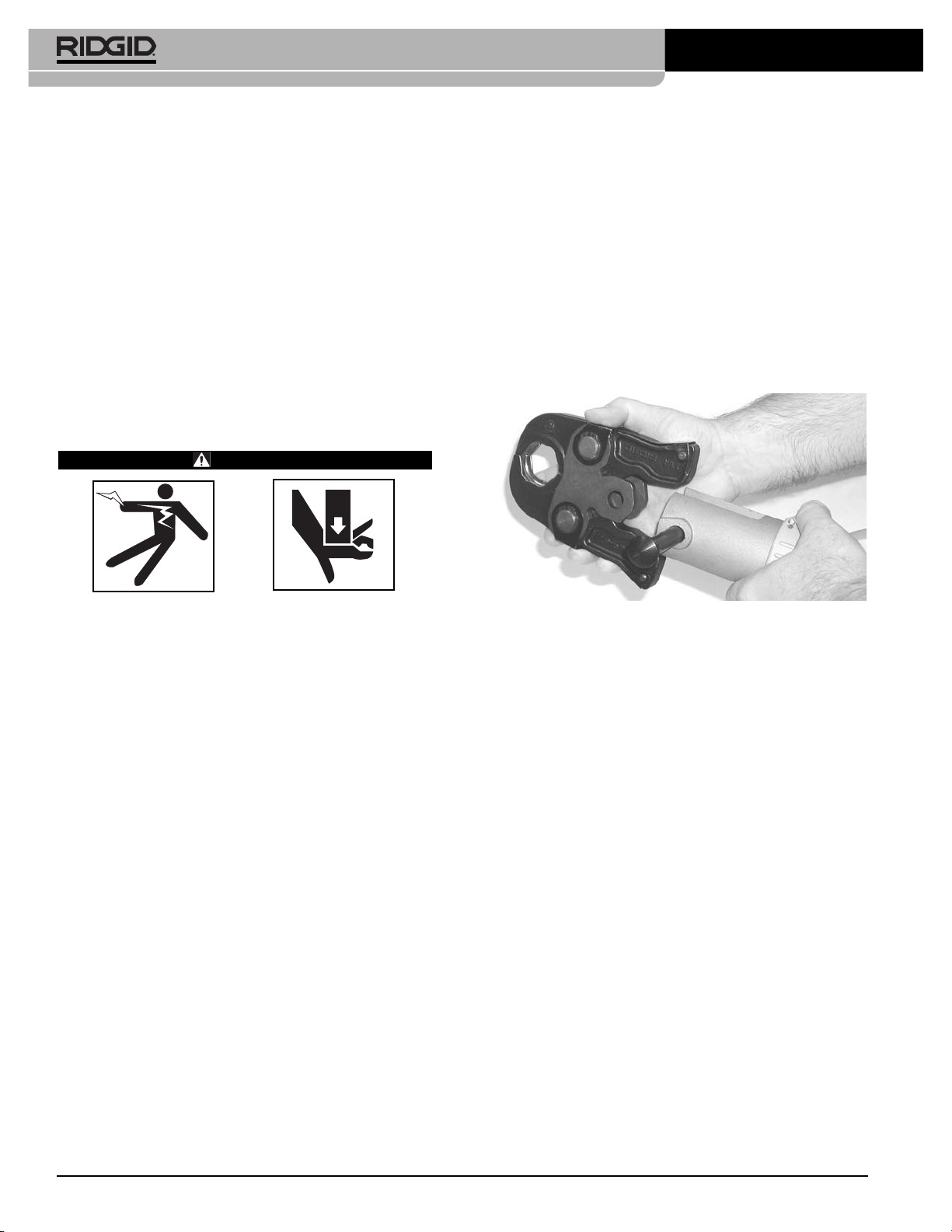
The ProPress XL-C rings must be used perpendicular to
the fitting and tube being pressed but the ball pocket/tip
feature on the rings and actuators allows the actuator and
press tool to swivel up to 90 degrees in each direction.
Figure 5 – ProPress XL-C Press Ring and RIDGID V2
Actuator
RIDGID Press Tool Attachments are protected under
various U.S. and International patents and pending patent
applications, including U.S. patents:
6,434,998 6,477,757 6,694,586 6,729,009 6,923,037
7,000,448 7,059,166 7,146,839 7,155,955 7,188,508
7,237,427 7,260,975 7,363,799 D562,098
Only use RIDGID Press Tools and RIDGID
press tool attachments (jaw sets, rings, actuators, etc.)
when specified by the fitting manufacturer for use with their
system. Use of incorrect press tools and/or attachments
for a system can cause system leaks, damage the press
tool or attachment, void warranties or cause severe per-
sonal injury.
Contact the fitting manufacturer for specific
information on their system, including compatible tubing,
materials, installation instructions, minimum distance
between fittings, seal material, inspection, testing, etc.
Incorrect installation can cause system leaks and exten-
sive property damage.
Contact Ridge Tool Technical Services Department at
list of press fitting system and valve manufacturers that
specify RIDGID pressing tools and attachments for their
systems.
Inspecting the Press Tool and
Attachments
WARNING
Inspect your pressing tool and attachments daily
and correct any problems to reduce the risk of seri-
ous injury from electric shock, tool and attachment
failure and other causes and to prevent tool and
property damage.
1. Inspect press tool according to the specific tool oper-
ator's manual.
2. Clean any oil, grease or dirt from the tool and attach-
ments, especially the handles and controls. This
reduces the risk of the tool or attachment slipping from
your grip and makes inspection easier.
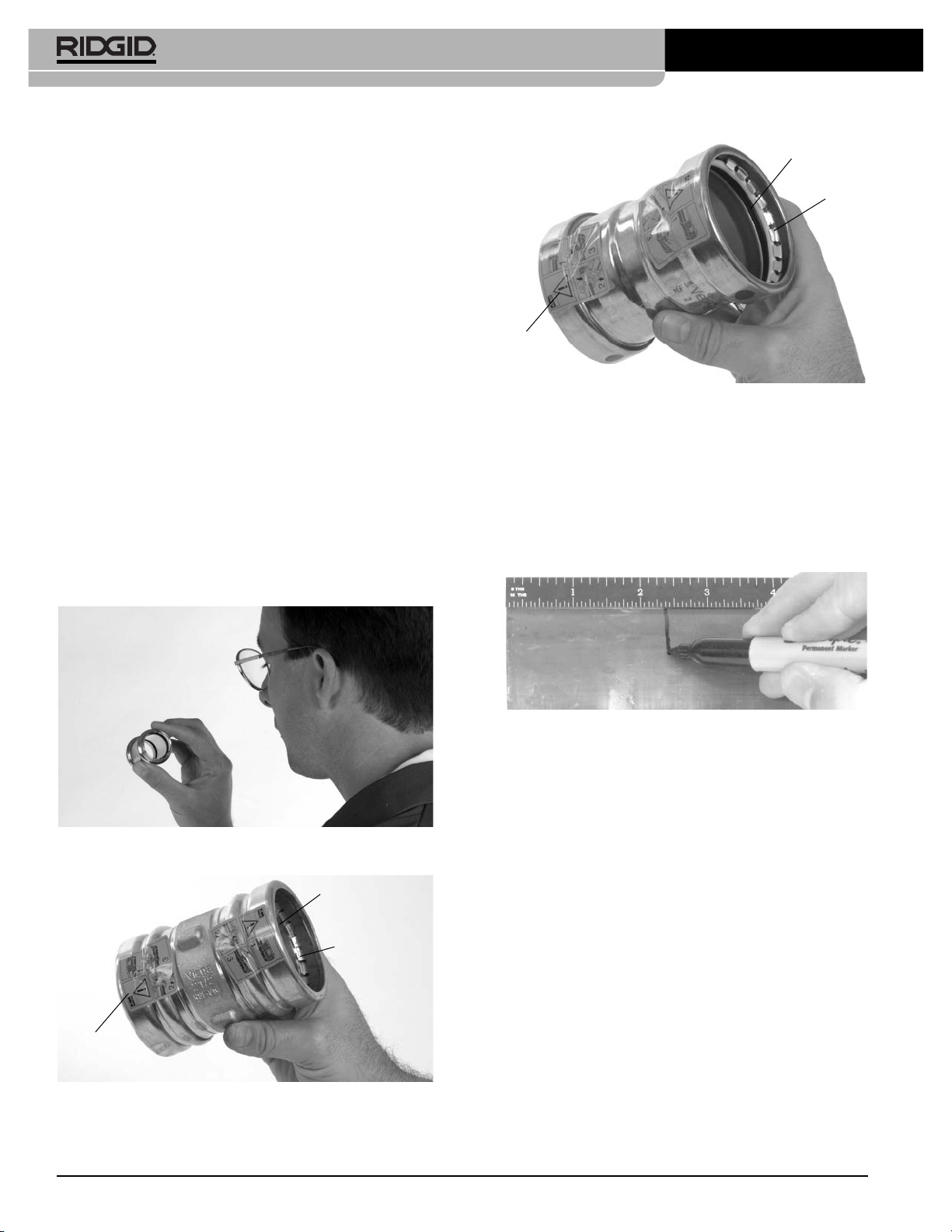
3. Closely inspect all pressing attachment components
(jaw sets, rings, actuators, etc.) for any cracked, bro-
ken, worn, missing, mis-aligned or binding parts or any
other sign of damage that may prevent proper and
safe operation. Damaged parts can cause the attach-
ment to make incorrect pressed connections or fail
during use, and cause serious injury or property dam-
age. If any damage is found, the attachment should
discarded and replaced.
Always discard the complete pressing
attachment. Never replace individual components or
exchange parts between assemblies. Failure to replace
the entire assembly may result in component failure
and serious injury.
Do not modify pressing attachments or use modified
attachments. A pressing attachment component that
has been welded, ground, drilled or modified in any
manner can shatter during pressing, resulting in sharp fly-
ing objects, severe injury or death. Discard and replace
damaged pressing attachments.
4. Inspect the attachment markings to make sure that it
is clearly marked as to the system and size that it is
appropriate for. Do not use an attachment that is not
clearly marked.
Ridge Tool Company 5
ProPress®Fitting System
Catalog No. Size Weight
20543 21/2" XL-C Press Ring 5.46 lbs (2,48 kg)
20548 3" XL-C Press Ring 9.63 lbs (4,37 kg)
20553 4" XL-C Press Ring 11.08 lbs (5,03 kg)
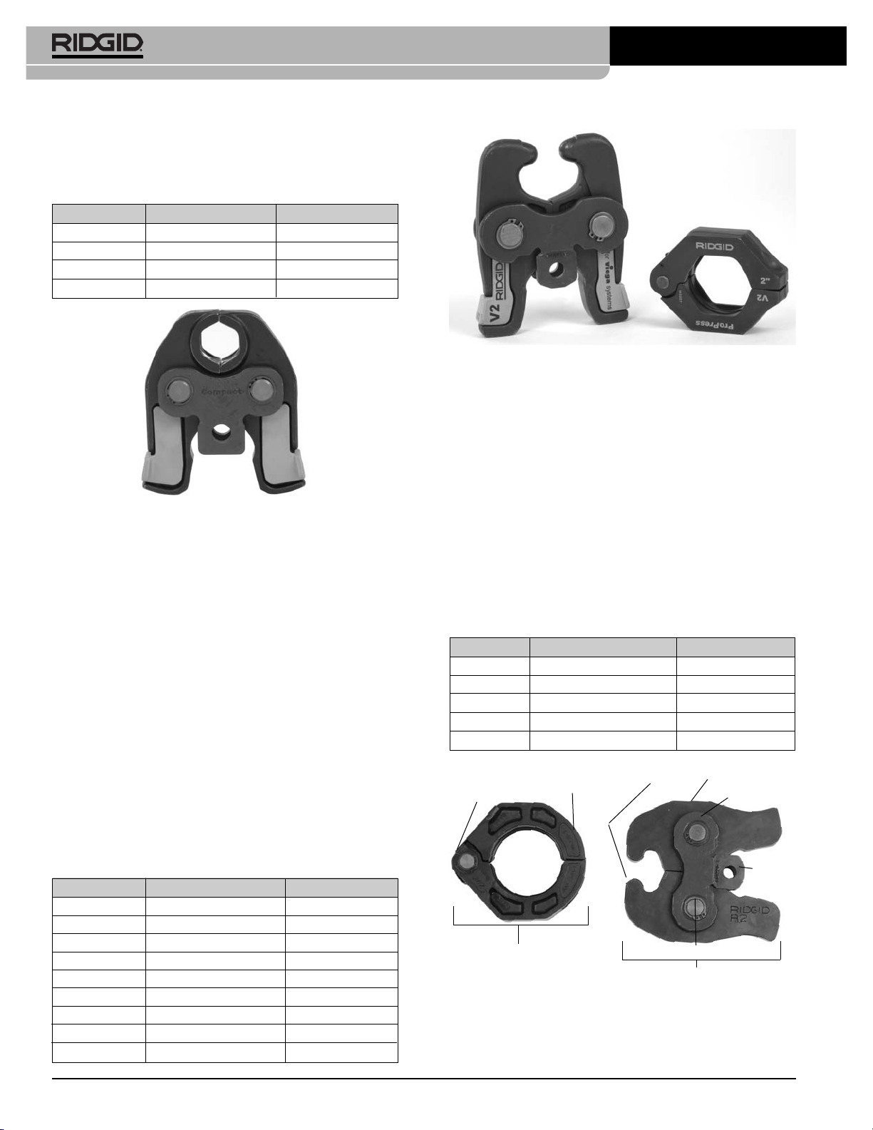
21878 V2 Actuator 6.71 lbs (3,04 kg)
21103 Carrying Case 6.15 lbs (2,79 kg)
Press Ring Actuator
Pocket (Not Visible) V2 Actuator Arm
V2 Side Plate
V2 Actuator
Torsion
Spring (Not
Visible)
ProPress XL-C Press Ring
XL-C Press Ring
Pivot Pin &
Torsion Spring
(Not visible)
RIDGID V2 Actuator
V2 Actuator
Spherical Tip
NOTICE
WARNING
WARNING

5. Inspect the press profile of the attachment. If it is
rusty, dirty or if there is a build up of fitting material,
clean as described in the maintenance section. It is
important to keep the press profile clean to prevent
the formation of burrs during pressing process, pre-
vent the attachment from sticking to the fitting and
making sure that a proper press connection is made.
6. Make sure that springs are intact and bias the attach-
ment in the proper direction (closed for rings, jaws and
actuators). Attachment should cycle freely from the
fully open to fully closed position. If needed, lubricate
pivot points with a light lubricating oil. Wipe any
excess oil from the attachment.
Tool and Work Area Set-Up
WARNING
Set up the press tool, attachment and work area
according to these procedures to reduce the risk of
injury from electric shock and other causes and to
prevent property damage.
1. Inspect the work to be done and determine
• The system of fittings to be used
• The sizes of fittings to be used
• The amount of space available for the tool and
attachments to make the pressed connections.
2. Determine the appropriate pressing tool and attach-
ments for the application.
See the Description and
Specification
section for information on the attach-
ments available for the ProPress systems. Information
on clearance requirements for various attachments can
be found at the back of the manual. Information on
RIDGID Pressing Tools and other RIDGID press tool
attachments can be found at www.RIDGID.com, or by
contacting Ridge Tool Technical Services at (800)
Only use RIDGID Press Tools and RIDGID press
tool attachments (jaw sets, rings, actuators, etc.)
when specified by the fitting manufacturer for use
with their system. Be sure to use the correct actuator
for the ring being used. Rings are marked to indicate
the correct actuator for use with the ring. Use of in-
correct press tools and/or attachments for a system
can cause system leaks, damage the press tool and
attachment or cause severe personal injury.
3. Make sure that the press tool and attachment have
been inspected according to their respective manuals
or instructions.
4. Follow tool set up procedure according to the specif-
ic press tool operator’s manual.
Mounting Attachment Into Press Tool
1. Make sure that the press tool is unplugged or that the
battery is removed from the tool.
2. Pull the attachment mounting pin on the press tool
out. If there is already an attachment in the tool, slide
it out of the pressing tool (
See Figure 6).
Figure 6 – Pulling The Jaw Set Mounting Pin Out
3. Slide the attachment into the press tool and fully
engage the attachment mounting pin. The press tool
will not function unless the pin is fully engaged.
Calibrating The Pressing Tool For The
Specific Pressing Attachment
(320-E Pressing Tool Only)
The RIDGID 320-E Pressing Tool includes a feature to
help insure that complete press connections are made. To
use this feature, when a press attachment is installed
on the 320-E, a calibration cycle is done. The 320-E then
compares that calibration cycle to each press connection
made. If the press connection does not match the cali-
bration cycle, the 320-E alerts the user that a pressing
error has occurred so that the operator can take appro-
priate action.
Specific calibration information is included here for each
type of attachment.
See the 320-E manual
or contact
Ridge Tool Technical Services if you have any ques-
tions regarding this feature.
Calibrating The 320-E With A Jaw Set
1. Make sure the 320-E Press Tool has the correct jaw
set installed.
2. Insert fully charged battery into the base of the 320-E
handle.
Ridge Tool Company6
ProPress®Fitting System

3. Depress ON/OFF button on display panel one time to
turn tool on. The audible alarm should beep once and
all three light emitting diodes (LED’s) will blink once.
Then, the green LED should be blinking indicating cal-
ibration is required.
Tool will automatically go into “sleep” mode if left
unused for ten (10) minutes. To “wake up” tool, it is
necessary to once again depress the ON/OFF button
on the top display panel.
4. Complete one tool cycle with an empty scissor style
jaw set (no fitting in jaw). Green LED should now
glow solid indicating tool is properly calibrated. The
tool is now ready to begin pressing fittings. The tool
will remain calibrated as long as jaw set is installed
unless tool is left idle for longer than sixty (60) minutes.
In this instance, which will be indicated by blinking
green LED after tool is turned back on, the calibration
process must be repeated.
Every time jaw set or actuator is replaced (jaw mount-
ing pin is opened), the calibration process should be
repeated to allow proper jaw closure detection.
Calibrating The 320-E With The R2
Actuator (For Use With ProPress XL
Rings)
1. Insert fully charged battery into the handle of the
320-E press tool.
2. Depress ON/OFF button on display panel one time to
turn tool on. The audible alarm should beep once and
all three light emitting diodes (LED’s) will blink once.
Then, the green LED should be blinking indicating cal-
ibration is required.
Tool will automatically go into “sleep” mode if left
unused for ten (10) minutes. To “wake up” tool, it is
necessary to once again depress the ON/OFF button
on the top display panel.
3. Complete one tool cycle with an empty R2 Actuator
(no press ring attached). Green LED will continue to
blink but the ram position detection feature is now dis-
abled. Due to the design of press rings, it is not pos-
sible to detect jaw closure since the rings never fully
close. The tool is now ready to begin pressing
ProPress XL fittings. The tool ram position detec-
tion will remain disabled as long as the ring actuator
is installed unless tool is left idle for longer than sixty
(60) minutes. In this instance, after the tool is turned
back on (by depressing the ON/OFF button on display
panel) the calibration process must be repeated.
Every time R2 Actuator is replaced the calibration
process should be repeated to disable the ram posi-
tion detection feature.
Calibrating The 320-E With The V1 Or
V2 Actuator (For Use With ProPress
Rings Or ProPress XL-C Rings)
1. Make sure the correct actuator (V1 or V2) is installed
in the 320-E.
2. Insert fully charged battery into the base of the 320-E
handle.
3. Depress ON/OFF button on the display panel one
time to turn tool ON. The audible alarm should beep
once and all three light emitting diodes (LED’s) will
blink once. Then, the green LED should be blinking
indicating calibration is required.
Tool will automatically go into “sleep” mode if left
unused for ten (10) minutes. To “wake-up” tool, it is
necessary to once again depress the ON/OFF button
on the top display panel.
4. Open the Actuator and engage onto the appropri-
ate Press Ring for the application.
5. Complete one tool cycle with the desired Actuator and
Ring (no fitting in press ring). Green LED should now
glow solid indicating tool is properly calibrated for
the selected Actuator and Ring combination. The
tool is now ready to begin pressing fittings. The tool
will remain calibrated as long as actuator is installed
unless tool is left idle for longer than sixty (60) minutes.
In this instance, which will be indicated by blinking
green LED after tool is turned back on, the cali-
bration process must be repeated.
6. If it is desired to change the size of fitting being
pressed and use a different size Ring that works with
the Actuator which is already installed in the tool, it is
necessary to recalibrate the new Ring/Actuator com-
bination. To accomplish this, the attachment mounting
pin must be partially opened and the fully inserted
again. This action will erase the previous calibration
setting. The green LED should now be blinking, indi-
cating the tool is ready for calibration. Next, repeat step
5 for the new Ring/Actuator combination.
Preparing The Connection
These are generalized instructions. Always fol-
low the fitting manufacturers specific installation instruc-
tions. Failure to follow the fitting manufacturer’s installation
instructions may lead to an improper press connection and
cause leaking connections and property damage.
Ridge Tool Company 7
ProPress®Fitting System
NOTICE

Preparing the Tube
1. If necessary, cut the desired length of the proper
tube for use with the fitting system. Use a tubing
cutter or other method that provides a clean cut
square to the axis of the tube. If using a vise or other
method to hold the tube during cutting, make sure that
the vise is far enough from the end of the tube not to
damage the section of tube that is inserted into the fit-
ting. Scratches on the outside diameter of the tube
and deformed tube can cause leaks.
2. Deburr the tube end inside and out with a file, ream-
er, deburring tool or other suitable tool. Burrs can cut
the sealing element of the fitting and cause leaks.
3. Clean the end of the tube of all dirt, oil and grease.
Improperly prepared tube can cause improper con-
nections, leaks and other property damage.
Inserting the Tube into the Fitting
1. Inspect the fitting per the manufacturer’s instructions
to be sure all parts are present, in place and free of
dirt and debris. If fitting parts are missing or dirty, this
can cause improper connections, leaks and other
property damage.
See Figure 7.
Figure 7A – Inspection of the ProPress Fitting per the
Manufacturer’s Instructions
Figure 7B – Inspection of ProPress XL Fitting Prior to
Tube Insertion
Ridge Tool Company8
ProPress®Fitting System
Figure 7C – Inspection of XL-C Fitting Prior to Tube
Insertion
2. In some systems, there is a requirement to mark the
tube before insertion. Check the fitting manufacturer’s
instructions, and if required, mark the tubing with a
permanent marker at the appropriate distance from
the tube end. This gives a visual reference that the
tube has been fully inserted into the fitting prior to
pressing the connection.
See Figure 8.
Figure 8 – Marking the Tube Before Inserting Into Fitting
3. Fully insert the tube into the fitting. Most fittings have
a stop that the tube end contacts to indicate full
insertion. Other fittings do not have a stop and will
allow the tube to fully pass through the fitting, and are
typically used in repair applications. If there is no
stop, insert the tube so that the mark made in the pre-
vious step is even with the end of the fitting. In some
cases, a twisting motion during insertion makes the
process easier. Never use any lubricant unless the fit-
ting manufacturer specifically advises to. Lubricants
can degrade the seal and cause leaks. Tubing that is
difficult to insert may be out of round or have burrs on
the tube end, which can damage the seal and cause
leaks.
4. Make sure that the tube is fully inserted in the fitting
and if not marked in previous steps, mark the tube at
the end of the fitting to give a visual reference that the
tube is fully inserted.
See Figures 9 and 10.
Seal
Stainless Steel
Grip Ring
Control
Label
Seal
Grip
Ring
Control
Label

Pressing the Connection with a Jaw Set
1. Squeeze the jaw arms to open the Jaw set and place
the open jaws around the fitting. Allow the jaw set to
close around the fitting, making sure to align the
press profile of the Jaw set with the contour of the fit-
ting
(See Figure 11)
.
Figure 11 – Opening the Jaw set and Placing Around
Fitting
2. Confirm that the tubing is inserted to the proper depth
in the fitting. As specified in appropriate Fitting System
instructions.
3. Make sure that the jaw set and pressing tool are
square to the tube and fitting
(See Figure 12)
and
depress the press tool switch. Keep fingers and
hands away from the jaw set to avoid crushing injuries
in jaw set and between the jaw set and the sur-
roundings.
Figure 12 – Jaw Set Square To Fitting and Tubing
The pressing cycle takes 4-8 seconds depending on
the press tool. Once a press cycle begins and the
rollers contact the Jaw set, the press tool will lock on
and automatically complete the press cycle. Releasing
the tool switch will not stop the tool once the pressing
process has begun. This insures consistent, repeatable
press connection integrity. If the tool should malfunc-
tion, refer to the specific press tool operator’s manual.
Ridge Tool Company 9
ProPress®Fitting System
Figure 9 – Marking the Tubing After Fully Inserting Tube
Figure 10 – Inserting the Tube Into Fitting to Proper Depth
Operating Instructions
WARNING
Always wear eye protection to protect your eyes
against dirt and other foreign objects.
Keep your fingers and hands away from the tool
attachment during the pressing cycle. Your fingers
or hands can be crushed fractured or amputated in
the attachment or tool or between the attach-
ment, work piece and other objects.
Follow operating instructions to reduce the risk of
injury from crushing and other causes and to pre-
vent tool damage.
Only use RIDGID Press Tools and RIDGID
press tool attachments (jaw sets, rings, actuators, etc.)
when specified by the fitting manufacturer for use with their
system. Use of incorrect press tools and/or attachments for
a system can cause system leaks, damage the press
tool or attachment, void warranties or cause severe per-
sonal injury.
Confirm that the tool and attachments have been properly
set up.
WARNING

Ridge Tool Company10
ProPress®Fitting System
2. Confirm that the appropriate actuator for the ring to be
pressed is in the pressing tool (the ring will be marked
with the designation of the appropriate actuator - R2,
V1, V2). The correct actuator/ring combination must
be used to prevent possible injury, ring and actuator
damage, and improper press connections. If using the
320-E Pressing Tool, make sure that the tool and
actuator have been calibrated to the ring being
pressed. If not see the calibration information in the
Set Up
section.
3. Squeeze the actuator arms to open the actuator tips,
place tips in ring pockets and allow the actuator to
close down and seat into the pockets.
See Figure 14A
– C
. The R2 actuator must be placed perpendicular to
the fitting/ring to properly seat in the ProPress XL ring
pockets, but the V1 and V2 actuators and their mating
rings are designed to allow the actuator and tool to be
rotated up to ninety degrees each way from perpen-
dicular. Make sure that the actuator tips are fully
engaged in the ring pockets.
Figure 14A – Placing R2 Actuator Tips Into XL Ring
Pockets
Figure 14B – Placing V2 Actuator Tips Into XL-C Ring
Pockets
4. Press the jaw set jaw arms to open the jaw set and
remove from the fitting. Avoid any sharp edges that
may have formed on fitting during pressing operation.
Pressing the Connection with a Ring
and Actuator
1. Open the appropriate Press Ring and place square-
ly around the fitting. Allow the ring to close around the
fitting, making sure to align the press profile with the
contour of the fitting. If the ring is not properly aligned
with the fitting, an improper press connection will be
made.
See Figures 13A, B and C.
Figure 13A – Installing ProPress XL Press Ring Onto
Fitting
Figure 13B – Installing ProPress XL-C Press Ring Onto
Fitting
Figure 13C – Installing ProPress Ring Onto Fitting
Detail A
Proper Press Ring
to Fitting Alignment

supplied by the manufacturer to indicate that the fitting
has not yet been pressed. Removal of the control
label indicates to others that the connection has been
pressed.
Look for the following:
• Excessive misalignment of the tubes. Note that a
slight amount of misalignment at the pressed con-
nection is considered normal.
• Tubes that are not fully inserted into the fitting – dou-
ble check the insertion marks made on the tube to
see that they are still aligned with the end of the fit-
ting.
• Incorrect jaw or ring alignment with the fitting con-
tour, distorted or deformed fitting.
• Any other issues per the fitting manufacturer.
If any of these problems are found, then removal of
the fitting is required and a new fitting and tube will
need to be prepared and pressed in its place.
2. If inspecting ProPress fittings, check and confirm the
presence of the ProPress witness mark in one of
the hex flats
(See Figure 15)
. This unique mark con-
firms that the proper RIDGID Jaw set, designed
specifically for the ProPress Fitting System was used
to make the pressed connection. This witness mark is
a trade mark of the Ridge Tool Company. Absence of
the witness mark may invalidate the system manu-
facturer’s warranty. The ProPress XL and ProPress
XL-C systems do not have a witness mark.
Figure 15 – ProPress Witness Mark
3. Test the system in accordance with the system sup-
pliers instructions, normal practice and local codes.
The system supplier may have specific system test
procedures to confirm the integrity of the system.
Figure 14C – Placing V2 Actuator Into XL-C Ring Pockets
At An Angle For Additional Clearance
Do not hang the actuator and tool from the ring. The
tool and actuator could fall from the ring and cause
serious injury or death.
4. Make sure that the ring is square to the tube and fit-
ting and depress the press tool switch. Keep fingers
and hands away from the actuator and ring to avoid
crushing injuries in the attachments and between
the attachments and surroundings.
The pressing cycle takes 4-8 seconds depending on
the press tool. Once a press cycle begins and the
rollers contact the actuator, the press tool will lock on
and automatically complete the press cycle. Re-
leasing the tool switch will not stop the tool once the
pressing process has begun. This insures consis-
tent, repeatable press connection integrity. If the tool
should malfunction, refer to the specific press tool
operator’s manual.
The ProPress rings and the ProPress XL-C rings
are designed to fully close during the pressing pro-
cess. The ProPress XL rings are not designed to
fully close during pressing. For the ProPress XL
rings, it is normal to have a gap between the ring tips
of approximately 5/16" (8 mm) at the end of the press
cycle.
5. After the pressing operation is complete, squeeze
the actuator arms to open the actuator tips and
remove from the ring.
6. Remove the ring from the fitting. Avoid any sharp
edges that may have formed on the fitting during
the pressing operation.
Inspecting The Press Connection
1. Inspect the pressed fitting. If the fitting is supplied with
a control label by the fitting manufacturer, remove it
(Refer to Figures 7B and 7C).
Control labels are
Ridge Tool Company 11
ProPress®Fitting System
Witness
Mark

Maintenance Instructions
WARNING
Press attachments should be removed from press
tool before performing any maintenance.
Always wear safety glasses. Protect your eyes from
dirt and other foreign objects.
A jaw, press ring or ring actuator component that
has been welded, ground, drilled or modified in any
manner can shatter during pressing, resulting in
sharp flying objects, severe injury or death. Discard
and replace damaged jaws, press rings or ring actu-
ators.
1. Inspect the jaws and press rings inside diameter daily
(Figure 17)
. If rusty, dirty or if there is evidence of fitting
material building up on the jaw or ring inside diameter,
(fitting material build-up is most likely to occur near the
tips of scissor style jaws or press rings as shown in
Figure 17
) clean with fine grade Scotch-Brite®(Scotch-
Brite®is a registered trademark of 3M Company)
metal polishing pads (or equivalent), steel wool or a
steel bristle wire brush.
Do not clean pressing profile with aggressive
abrasive materials or methods, such as emery cloth,
sandpaper, grinding wheels or rotary files. These meth-
ods may alter critical pressing profile dimensions and
cause improper pressed connections that can lead to
extensive property damage.
Figure 17 – Fitting Material Build-Up Requiring Jaw
Cleaning
2. Pivot pins and moving points on jaws, press rings and
actuators should be cleaned and lubricated at least
once a month with a light weight general purpose
lubricating oil.
3. Check return springs in press jaws, rings and ring
actuators with each use. Jaws and ring actuators
should open and close freely with only moderate fin-
ger effort required.
Ridge Tool Company12
ProPress®Fitting System
Accessories
WARNING
Only the following RIDGID ProPress products have
been designed to function with RIDGID Press Tools.
Other press tool attachments and accessories suit-
able for use with other tools may become hazardous
and/or produce bad presses.
To prevent serious injury when pressing ProPress fit-
tings, only use attachments such as those listed
below.
ProPress System:
Standard Series ProPress Jaw Sets
Compact Series ProPress Jaw Sets
ProPress Rings
Catalog
No. Description
76652 1/2" ProPress Jaw Set
76657 3/4" ProPress Jaw Set
76662 1" ProPress Jaw Set
76667 11/4" ProPress Jaw Set
76672 11/2" ProPress Jaw Set
76677 2" ProPress Jaw Set
Catalog
No. Description
16958 1/2" ProPress Jaw Set
16963 3/4" ProPress Jaw Set
16978 1" ProPress Jaw Set
31228 11/4" ProPress Jaw Set
Catalog
No. Description
27998 1/2" ProPress Ring
28003 3/4" ProPress Ring
28008 1" ProPress Ring
28013 11/4" ProPress Ring
28018 11/2" ProPress Ring
28023 2" ProPress Ring
26163 C1 Actuator
28033 V1 Actuator
21878 V2 Actuator
28043 C1 Kit, 1/2" - 11/4"
27423 V1 Kit, 1/2" - 11/4"
28048 V1/C1 Combo Kit, 1/2" - 11/4"
27428 V2 Kit, 11/2" - 2"
28028 Carrying Case for 1/2" - 11/4" Ring Kits
28038 Carrying Case for 11/2" - 2" Ring Kit
NOTICE

Ridge Tool Company 13
ProPress®Fitting System
ProPress XL Press Rings
ProPress XL-C Press Rings
Catalog
No. Description
93677 21/2" ProPress XL Press Ring Set
93682 3" ProPress XL Press Ring Set
93687 4" ProPress XL Press Ring Set
93692 R2 Actuator
16803 ProPress XL Set Carrying Case
93667 R2 Kit, 21/2" - 4"
Catalog
No. Description
20543 21/2" ProPress XL-C Press Ring Set
20548 3" ProPress XL-C Press Ring Set
20553 4" ProPress XL-C Press Ring Set
21878 V2 Actuator
21103 ProPress XL-C Set Carrying Case
20483 V2 Kit, 21/2" - 4"
Machine Storage
These tools and attachments must be
kept indoors or well covered in inclement weather. Store
in a locked area out of the reach of children and people
unfamiliar with the tools. These tools can cause serious
injury in the hands of untrained users.
Service and Repair
WARNING
Improper service or repair can make attachments
unsafe to operate.
The “Maintenance Instructions” will take care of most of the
service needs of this machine. Any problems not ad-
dressed by this section should only be handled by an
authorized RIDGID service technician.
No Service parts are sold for these attachments. If parts
are needed, the attachment should be discarded and a
new unit purchased.
For information on your nearest RIDGID Independent
Service Center or any service or repair questions:
• Contact your local RIDGID distributor.
• Visit www.RIDGID.com or www.RIDGID.eu to find
your local Ridge Tool contact point.
• Contact Ridge Tool Technical Services Department at
call (800) 519-3456
WARNING

Ridge Tool Company14
ProPress®Fitting System
A
B
Clearance Requirements – Compact Series
ProPress Jaw Sets
A
B
C
20°
Tube Dia. A (min.) B (min.)
Inches mm Inches mm
1/2"3/4"19 2" 51
3/4"7/8"222
3/8"60
1" 1" 26 25/8"67
11/4"1
1/828 31/879
Tube Dia. A (min.) B (min.) C (min.)
Inches mm Inches mm Inches mm
1/2"7/8"231
3/8"352
1/2"64
3/4"1"261
1/2"382
3/4"70
1" 11/8"291
5/8"41 3" 76
11/415/8"392
1/8"533
3/8"85
Tube Dia. A (min.) B (min.)
Inches mm Inches mm
1/2"3/4"191
5/8"41
3/4"7/8"222
1/8"54
1" 1" 26 21/2"64
11/4"1
1/8"292
7/8"73
11/2"1
3/4"453
1/2"89
2" 2" 51 43/8" 111
Tube Dia. A (min.) B (min.) C (min.)
Inches mm Inches mm Inches mm
1/2"7/8"231
3/8"352
1/2"64
3/4"1"261
1/2"382
1/2"64
1" 11/8"291
3/4"45 3" 76
11/4"1
1/4"322
1/4"573
1/8"80
11/2"1
7/8"482
1/2"643
3/4"95
2" 21/8"543
1/8" 80 5" 127
B
A
C
A
B
Clearance Requirements
The following figures illustrate the clearance require-
ments for the jaws and fittings and the procedure for
pressing fittings in tight quarters with rings.
Clearance Requirements – Standard Series
ProPress Jaw Sets

Tube Dia. A (min.) B (min.) C (min.)
Inches mm Inches mm Inches mm
1/2"1
5/8"413
1/4"83 2" 51
3/4"1
3/4"453
1/4"831
7/8"48
1" 2" 51 31/4"831
7/8"48
11/4"2
3/16"55 3
3/8"861
7/8"46
C1
Tube Dia. A (min.) B (min.) C (min.)
Inches mm Inches mm Inches mm
11/2"2
3/8" 60 5" 127 23/16"56
2" 29/16"65 4
3/4" 121 29/16"65
V2
Ridge Tool Company 15
ProPress®Fitting System
Clearance Requirements – ProPress Rings
B
B
A
Tube Dia. A (min.) B (min.) C (min.)
Inches mm Inches mm Inches mm
1/2"2
1/4"572
1/8"541
1/16"27
3/4"2
11/16"68 2
7/8"731
1/8"28
1" 215/16"75 3
5/16"841
3/16"31
11/4"3
5/16"84 3
7/8"991
3/16"30
11/2"3
11/16"94 4
5/16" 110 13/16"31
2" 47/16" 113 57/16" 139 13/16"30
A
B
Tube Dia. A (min.) B (min.)
Inches mm Inches mm
1/2"1
5/8"412
13/16"71
3/4"1
3/4"452
3/16"55
1" 2" 51 15/8"42
11/4"2
3/16"552
15/16"75
11/2"2
3/8"603
5/16"85
2" 29/16"65 4
1/8" 105
Tube Dia. A (min.) B (min.) C (min.)
Inches mm Inches mm Inches mm
1/2"1
5/8"413
9/16"902
5/16"59
3/4"1
3/4"453
5/8"922
1/8"55
1" 2" 51 313/16"97 2
3/16"56
11/4"2
3/16"55 3
3/4"922
1/8"55
B
C
A
C
V1

Ridge Tool Company16
ProPress®Fitting System
Tube Dia. A (min.) B (min.) C (min.)
Inches mm Inches mm Inches mm
21/2"5
9/16" 141 71/8" 181 15/8"41
3" 61/8" 156 715/16" 202 111/16"43
4" 75/16" 186 95/8" 244 13/4"44
C
B
A
Tube Dia. A (min.) B (min.)
Inches mm Inches mm
21/2"3
3/8"865
3/8" 137
3" 35/8" 92 6" 152
4" 41/4" 108 73/8" 188
Tube Dia. A (min.) B (min.) C (min.)
Inches mm Inches mm Inches mm
21/2"3
3/8"865
3/8" 137 33/4"95
3" 35/8" 92 6" 152 41/8" 105
4" 41/4" 108 73/8" 188 5" 127
B
B
A
B
C
A
Clearance Requirements – ProPress XL Press Rings

Ridge Tool Company 17
ProPress®Fitting System
1. Place the press ring
around the fitting from
the front...
2. ...until the press ring is
resting in the groove
of the fitting.
3. Keep the press ring
closed and rotate about
the fitting until the open-
ing is toward the front.
4. Insert the press ring
actuator and start the
press cycle.
Tight Quarter Pressing Procedure – Pressing Rings
Tube Dia. A (min.) B (min.) C (min.)
Inches mm Inches mm Inches mm
21/2"6
3/16" 157 615/16" 176 77/16"62
3" 77/16" 189 813/16" 224 27/16"62
4" 81/16" 205 107/16" 265 27/16"62
C
B
A
Tube Dia. A (min.) B (min.) C (min.)
Inches mm Inches mm Inches mm
21/2"4
1/8" 105 6" 152 41/2" 114
3" 45/8" 111 7" 178 47/8" 124
4" 5" 127 8" 203 53/4" 146
B
C
A
Tube Dia. A (min.) B (min.)
Inches mm Inches mm
21/2"4
1/8" 105 6" 152
3" 43/8" 111 7" 178
4" 5" 127 8" 203
B
B
A
Clearance Requirements – ProPress XL-C Press
Rings

Ridge Tool Company18
ProPress®Fitting System
SYMPTOM POSSIBLE REASONS SOLUTION
Press connections pro-
duced are not complete.
Excessively large or
sharp fins present at
press joint parting line
where jaw or ring tips
come together.
Jaws or rings stick to fit-
ting excessively after
completing press joint.
Troubleshooting
Used wrong jaw set or press ring for the tube size
or material.
The jaw set or ring contour was not square to the
tube.
The jaw set or ring has exceed life expectations and
may have failed.
Fitting material build up on jaws or press rings in
the contoured profile area near jaw or ring tips.
Excessively worn or damaged jaws or press rings.
Fitting material build-up on jaws or press ring in
the contoured profile area near jaw or ring tips.
Install correct jaw set.
Redo the joint using new tube and fitting and make
sure that the jaw set or ring is square to the fitting.
If cracked, replace old jaw set with a new jaw set
and redo the joint using new tube and fitting.
Clean jaw or press ring in the contoured area
using metal polishing pads such as Scotch-Brite®.
Refer to Maintenance Section for instructions.
Discard jaws or press ring and replace with new
RIDGID jaw set or press ring.
Clean jaw or press ring contour area using metal
polishing pads such as Scotch-Brite®. Refer to
Maintenance Section for instructions.
This manual suits for next models
3
Table of contents
Languages:
Other RIDGID Power Tools Accessories manuals
Popular Power Tools Accessories manuals by other brands

Milwaukee
Milwaukee 5317-DE Operator's manual

Toro
Toro 132-4193 installation instructions

Festo
Festo DFST-G2 Series Instructions & Operating

Central Machinery
Central Machinery 92247 Assembly and operating instructions

AXXAIR
AXXAIR 81M21 operating instructions

Gardner Bender
Gardner Bender Slug Out KOMD1 instruction manual