Ridge Tool Company 3
Personal Safety
•Stay alert, watch what you are doing and use com-
mon sense when operating a power tool. Do not
use a power tool while you are tired or under the
influence of drugs, alcohol, or medication. A mo-
ment of inattention while operating power tools may
result in serious personal injury.
•Use personal protective equipment. Always wear
eye protection. Protective equipment such as dust
mask, non-skid safety shoes, hard hat, or hearing
protection used for appropriate conditions will reduce
personal injuries.
•Prevent unintentional starting. Ensure the switch
is in the off-position before connecting to power
source and/or battery pack, picking up or carrying
the tool. Carrying power tools with your finger on the
switch or energizing power tools that have the switch
on invites accidents.
•Remove any adjusting key or wrench before turn-
ing the power tool on. A wrench or a key left attached
to a rotating part of the power tool may result in per-
sonal injury.
•Do not overreach. Keep proper footing and bal-
ance at all times. This enables better control of the
power tool in unexpected situations.
•Dress properly. Do not wear loose clothing or
jewelry. Keep your hair, clothing, and gloves away
from moving parts. Loose clothes, jewelry, or long
hair can be caught in moving parts.
•If devices are provided for the connection of dust
extraction and collection facilities, ensure these are
connected and properly used. Use of dust collection
can reduce dust-related hazards.
Power Tool Use And Care
•Do not force power tool. Use the correct power tool
for your application. The correct power tool will do the
job better and safer at the rate for which it is designed.
•Do not use power tool if the switch does not turn it
ON and OFF. Any power tool that cannot be con-
trolled with the switch is dangerous and must be
repaired.
•Disconnect the plug from the power source and/or
the battery pack from the power tool before mak-
ing any adjustments, changing accessories, or
storing power tools. Such preventive safety mea-
sures reduce the risk of starting the power tool acci-
dentally.
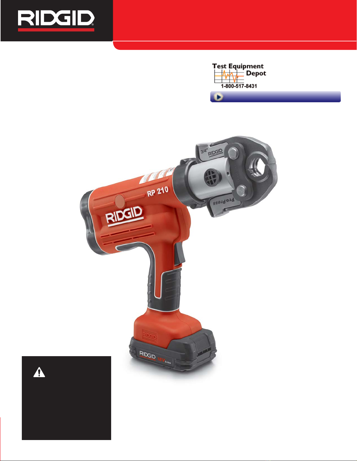
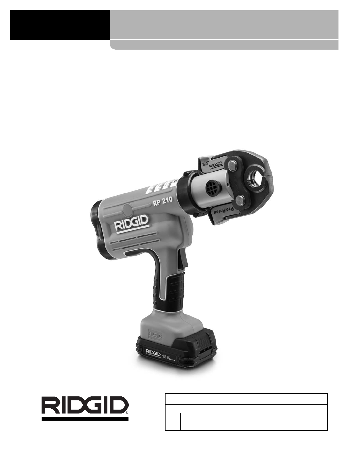
RP 210 Press Tool
•Store idle power tools out of the reach of children
and do not allow persons unfamiliar with the pow-
er tool or these instructions to operate the power
tool. Power tools are dangerous in the hands of
untrained users.
•Maintain power tools. Check for misalignment or
binding of moving parts, breakage of parts and any
other condition that may affect the power tool’s op-
eration. If damaged, have the power tool repaired
before use. Many accidents are caused by poorly
maintained power tools.
•Keep cutting tools sharp and clean. Properly main-
tained cutting tools with sharp cutting edges are less
likely to bind and are easier to control.
•Use the power tool, accessories and tool bits etc.
in accordance with these instructions, taking into
account the working conditions and the work to be
performed. Use of the power tool for operations dif-
ferent from those intended could result in a hazardous
situation.
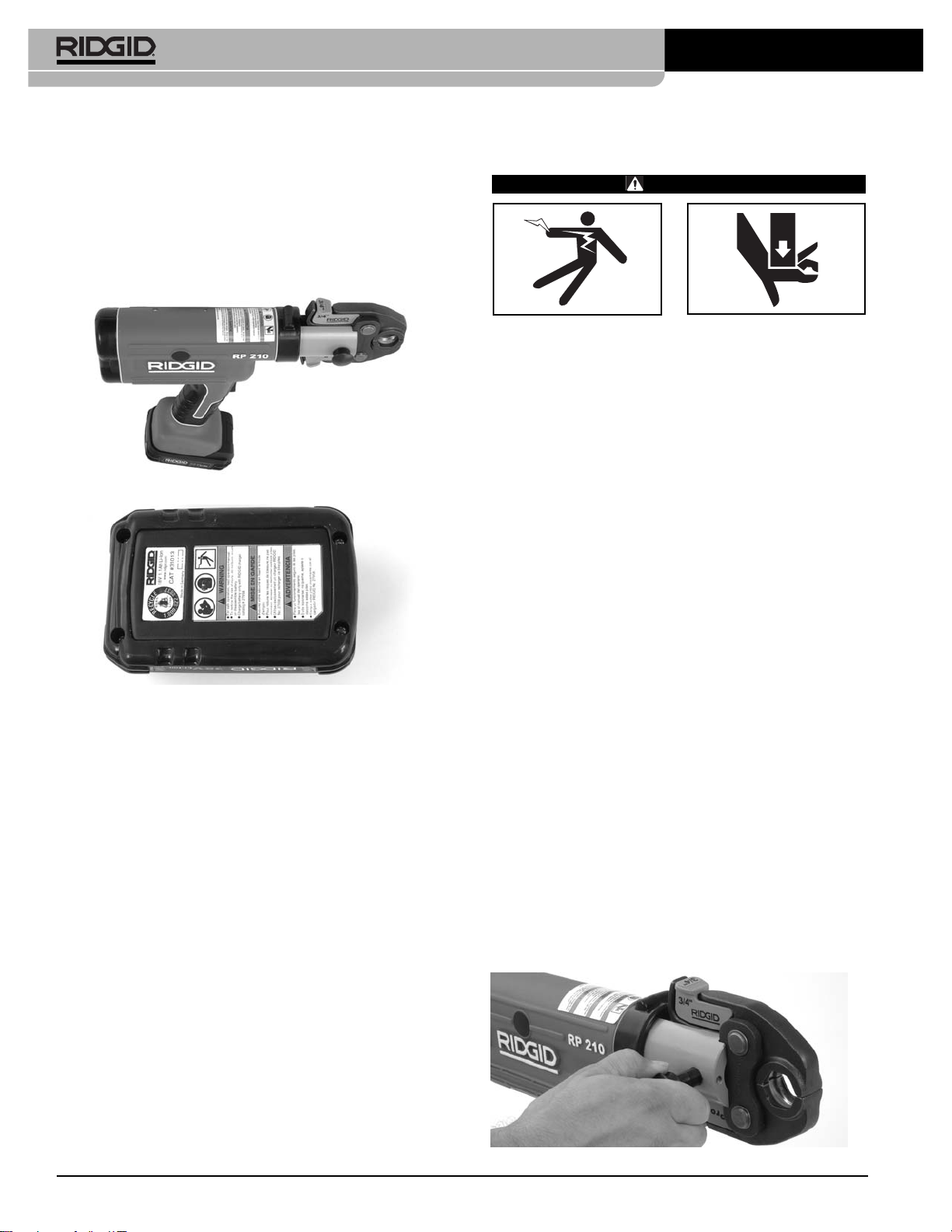
Battery Tool Use And Care
•Recharge only with the charger specified by the
manufacturer. A charger that is suitable for one type
of battery pack may create a risk of fire when used with
another battery pack.
•Use power tools only with specifically designated
battery packs. Use of any other battery packs may
create a risk of injury and fire.
•When battery pack is not in use, keep it away
from other metal objects, like paper clips, coins,
keys, nails, screws or other small metal objects
that can make a connection from one terminal to
another. Shorting the battery terminals together may
cause burns or a fire.
•Under abusive conditions, liquid may be ejected
from the battery; avoid contact. If contact acciden-
tally occurs, flush with water. If liquid contacts
eyes, additionally seek medical help. Liquid ejected
from the battery may cause irritation or burns.
Service
•Have your power tool serviced by a qualified repair
person using only identical replacement parts.
This will ensure that the safety of the power tool is
maintained.