RIDGID JP0600 User manual

2:1(5·60$18$/
$VVHPEO\
2SHUDWLRQ
5HSDLU3DUWV
)RU<RXU6DIHW\
5HDGDOOLQVWUXFWLRQVFDUHIXOO\
48(67,21625&200(176"
&$//5,'*,'
ZZZULGJLGZRRGZRUNLQJFRP
Part No. SP6173 Printed in Taiwan
-3
-2,17(53/$1(5

2
Table of Contents
Safety Instructions For Jointer/Planer ..........................3
Safety Signal Words ..................................................3
Major Hazards ............................................................3
Before Using the Jointer/Planer .................................3
Safety Labels and Indicators on the Jointer/Planer ...4
When Installing Or Moving the Jointer/Planer ............4
Before Each Use ........................................................4
To Reduce the Risk of Injury From Jams, Slips Or
Thrown Pieces (Kickbacks Or Throwbacks) .............5
Plan Ahead To Protect Your Eyes, Hands, Face
and Ears ...................................................................5
Inspect Your Workpiece .............................................5
Whenever Jointer/Planer Is Running .........................6
Before Leaving the Jointer/Planer ..............................6
Glossary of Terms for Woodworking ............................6
Motor Specifications and Electrical Requirements .......7
Power Supply and Motor Specifications ....................7
General Electrical Connections ..................................7
110-120 Volt, 60 Hz. Tool Information .......................7
Changing Motor Voltage ............................................8
Motor Safety Protection .............................................9
Wire Sizes ..................................................................9
Unpacking and Checking Contents ............................10
Tools Needed ...........................................................10
Unpacking ................................................................10
List of Loose Parts ...................................................10
Loose Parts ..............................................................11
Loose Parts (From Bag Assembly) ..........................12
Assembly ....................................................................13
Assemble The Cabinet .............................................13
Install the Leveling Feet ...........................................13
Assembling Cabinet Top/Motor Mount Assembly ....14
Attaching Motor Pulley .............................................15
Assemble Motor To Cabinet Top .............................15
Assembling Cabinet Top to Cabinet ........................16
Assemble Bed to Stand ...........................................16
Mounting On-Off Switch ...........................................17
Attach Front of Cabinet and Dust Chute ..................17
Assemble Fence To Bed ..........................................18
Install Cutter Head Guard ........................................18
Cutter Head Guard Functional Check ......................18
Adjusting Guard Spring ............................................19
Attaching Pulley Guard ............................................19
Installing Rear Cutter Head Guard ..........................19
Adjusting the Leveling Feet ........................................19
Getting to Know Your Jointer/Planer ..........................20
Alignments ..................................................................22
Cutter Knife Alignment/Adjustments ........................22
Cutter Knife Sharpening ..........................................23
Adjusting Table Extension .......................................23
Outfeed Table Adjustment .......................................24
Adjusting Table Gibs ................................................25
Fence Tilt (Bevel Stop) Alignment ...........................25
Safety Instructions for Basic Jointer/Planer
Operation ................................................................26
Feeding the Workpiece (All Operations) ..................26
To Reduce the Risk of Injury From Jams, Slips Or
Thrown Pieces (Kickbacks Or Throwbacks) ...........26
Plan Ahead to Protect Your Eyes, Hands, Face
and Ears .................................................................27
Whenever Jointer/Planer Is Running .......................27
Basic Jointer/Planer Cutting Operations ....................28
Depth of Cut Handwheel Operation .........................28
Stop Pin Operation ..................................................28
Feeding the Workpiece ............................................28
Planing .....................................................................29
Jointing ....................................................................29
Beveling/Chamfering ...............................................29
Rabbeting ................................................................30
Stop Pin Operation ..................................................30
Support Long Workpieces .......................................30
Using the Hold-Down/Push-Blocks ..........................30
Sliding Fence Operation ..........................................31
Fence Tilt Operation ................................................31
Maintenance and Lubrication .....................................32
Maintenance ............................................................32
Lubrication ...............................................................32
Wiring Diagram ...........................................................33
Troubleshooting Guide ...............................................34
General ....................................................................34
Motor ........................................................................35
Repair Parts ...............................................................36

3
Safety Instructions For Jointer/Planer
Safety is a combination of common sense, staying alert and knowing how your jointer/planer works. Read this manual
to understand this tool.
Safety Signal Words
DANGER: means if the safety information is not followed
someone will be seriously injured or killed.
WARNING: means if the safety information is not followed
someone could be seriously injured or killed.
CAUTION: means if the safety information is not followed
someone may be injured.
Major Hazards
All of the safety information and cutting steps are critical
to the safe operation of the jointer/planer.
1. Workpiece kickback
Kickback is the uncontrolled grabbing and throwing of the
workpiece during jointing or planing. If kickback occurs,
the workpiece can hit you or a bystander hard enough to
cause broken bones, internal organ injury or death. To
reduce or prevent kickback, read and follow the safety
information in the Jointing and Planing sections of the
manual.
2. Kickback followed by blade contact
Your fingers or hand can contact the blade following kick-
back if your hands are unprotected or too near the cutter
blades. Your fingers can be cut off. To reduce the risk of
contacting the cutting blades, read and follow the safety
information in the Jointing and Planing sections of the
manual.
3. Wrong way feed
Wrong way feed is feeding the workpiece into the cutter
blades in the direction of blade rotation. The workpiece
can be grabbed by the blades and pull your hands into
the blades before you can let go or pull back. Fingers can
be cut off. To reduce the risk of wrong way feed, always
feed the workpiece against the direction of blade rotation.
Cutter blade rotation is shown on the sliding fence guard
(behind the center of the fence).
4. Thrown workpiece, chips and cutter blade pieces
The jointer/planer can throw the workpiece, workpiece
chips, or pieces of loose or broken cutter blades. You can
be blinded. Wear safety goggles labelled “ANSI Z87.1” (or
in Canada CSA Z94-3-M88) on the package.
DANGER: Follow the steps listed below to reduce
or eliminate the risk of being injured when using
the jointer/planer. Failure to do so can result in a
life threatening injury or death.
1. Lock the fence lock knob and the sliding guard
knob.
2. Set the depth of cut to less than 1/8" for jointing
and less than 1/32" for planing.
3. Check the blade guard for proper position and
smooth operation.
4. Keep hands as far away from the cutters as pos-
sible when jointing or planing.
5. Use push blocks or push sticks whenever possi-
ble.
6. Complete the cut without stopping or backing up
the workpiece.
7. Read and follow the safety information and
safety instructions in the operator’s manual and
in the safety labels on the jointer/planer.
8. Know location and function of all controls before
using tool. See “Getting to know your Jointer/
Planer” section of this manual.
Before Using the Jointer/Planer
WARNING: To reduce the risk of mistakes that
could cause serious, permanent injury, do not plug
the jointer/planer in until the following steps have
been satisfactorily completed.
Know and Understand the Jointer/Planer
• Completely assemble and align jointer/planer.
• Learn the use and function of the ON-OFF switch,
fence slide locking handle, cutter guard, depth of cut
hand wheel, locks and stops, fence bevel lock handle,
outfeed table, infeed table and hold-down/push-blocks.
• Review and understand all safety instructions and
operating procedures in this manual.
• Review the maintenance methods for this jointer/
planer.
• Find and read the warning label found on the jointer/
planer (shown below).

4
Safety Instructions For Jointer/Planer (continued)
Safety Labels and Indicators on the Jointer/Planer
The following labels and indicators are on your jointer/
planer. Locate, read and follow the safety instructions
and information contained in these labels.
1. Safety instruction label on the top of the guard.
2. Cutter rotation indicator is on top of the sliding guard.
3. Cutter position indicator is on top of the fence.
Push blocks and push sticks
Two plastic push blocks are supplied with your jointer/
planer. Use them when practical. The rubber sole of the
push blocks give better traction with the wood than your
hands do. If they become slippery, they can be cleaned
with rubbing alcohol, paint thinner or sandpaper.
CAUTION: Use rubbing alcohol or paint thinner
only as described on their containers. Use only in
well ventilated areas away from open flames,
sparks or heat sources.
Push blocks can’t always be used. With larger work-
pieces, you may have better control fo the workpiece
using your hands. Always make a test pass first to deter-
mine which method gives you better control.
Before you make any cut, plan your hand positions. If a
kickback should occur, plan so that your hands will not fall
or be forced into the cutters.
Three Inch Rule (3")
Generally, if your hands are closer than three inches to
the blade as you feed the wood, use push blocks. This
gives extra protection to your hands by placing the push
blocks between your hands and the cutters.
Always Use Push Blocks When Planing, Beveling Or
Chamfering
When jointing, test for workpiece stability before actually
jointing, and use push blocks when you can without sacri-
ficing control.
When Installing Or Moving the Jointer/Planer
Reduce the Risk of Dangerous Environment.
• Use the jointer/planer in a dry, indoor place protected
from rain.
• Keep work area well lighted.
To reduce the risk of injury from unexpected jointer/
planer movement.
• Bolt or clamp the jointer/planer to firm level surface
where there is plenty of room for moving the workpiece
through the entire cut.
• Support the jointer/planer so the tables are level and
the jointer/planer does not rock.
• Put the jointer/planer where neither operators nor
bystanders must stand in line with the wood while plan-
ing or jointing it.
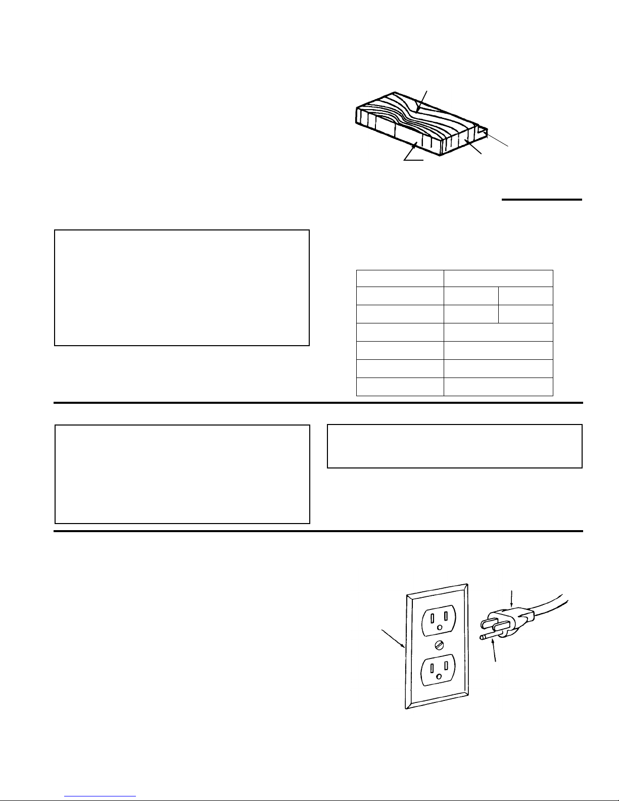
• To reduce the risk of injury from electrical shock, make
sure your fingers do not touch the plug’s metal prongs
when plugging in or unplugging the jointer/planer.
• Turn off and unplug the jointer/planer before moving it
to a new area. To reduce the risk of back injury, get
help when you need to lift or move the jointer/planer.
• Bolt the jointer/planer to the floor if it tends to slip, walk,
slide or tip over. Be especially aware of movement
when jointing/planing long heavy boards.
•Never Stand On Tool. Serious injury could occur if the
tool tips or you accidentally hit the cutter head. Do not
store anything above or near the tool where anyone
might stand on the tool to reach them.
Before Each Use
Inspect your jointer/planer.
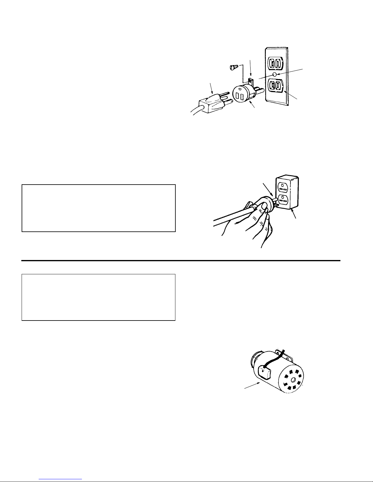
WARNING: The 2-1/2
inch jointer/planer pulley and
the 3-1/2 inch motor pulley furnished will run the
cutter head at about 5000 RPM when used with a
3450 RPM motor. Use of different types of pulleys
or motors will change this speed and could cause
jamming, binding, kickback, thrown knives or
other dangers.
• To reduce the risk of injury from accidental starting, turn
the switch off, unplug the jointer/planer, and remove the
switch key before moving the cutter head guard, chang-
ing the blades, changing the setup, or adjusting any-
thing.
• Check for alignment of moving parts, binding of moving
parts, breakage of parts, unit stability, and any other con-
ditions that may affect the way the jointer/planer works.
• Don’t force the tool. It will do the job better and safer at
the rate for which is was designed.
• If any part is missing, bent or broken in any way, or any
electrical part does not work properly, turn the jointer/
planer off and unplug the jointer/planer.
• Replace damaged, missing or failed parts before using
the jointer/planer again.
• Make sure the cutter guard works properly. With the
switch off and key removed, pull the cutter guard open
and let go. If the guard doesn’t smoothly swing closed,
contact an Authorized Service Center.
• Make sure the cutter head turns in the right direction.
The top should move toward the infeed table. If the cut-
ter head turns the wrong direction, contact an Autho-
rized Service Center.
• Keep Jointer/Planer interior free of wood chips and
dust buildup around motor and switch box.
• Keep knives sharp. Dull or nicked knives tend to
“pound” and chew at the wood, causing kickbacks.
• To reduce the risk of injury from unsafe accessories,
use only recommended accessories.

5
To Reduce the Risk of Injury From Jams, Slips Or Thrown Pieces (Kickbacks Or Throwbacks)
• Use this jointer/planer to cut only wood.
• Use push blocks or push sticks whenever possible.
• Plan your hand placement so your fingers will not be
anywhere a sudden slip could cause them to slide or
fall into the cutter head. When using only one hold-
down/push-block to feed the wood, do not put your
other hand on the jointer/planer, workpiece, or hold-
down/push-block.
• To reduce the risk of injury from thrown pieces, make
sure the knives are sharp, properly installed and the
cutter knives wedge screws are tight.
• Make sure the clamps and locks are tight and there is
not excessive play in any parts.
• Adjust the depth of cut to between 1/32 and 1/16 of an
inch for best results in most operations. A deep cut
makes feeding the wood harder and can cause the
wood to kickback. To be sure you will make a depth of
cut you planned, always lower the infeed table slightly
farther than you wanted then, raise the table to the
desired depth.
• Use The Right Tool. Don’t force tool or attachment to
do a job it was not designed for.
Inspect your work area.
• Keep work area clean.
• Cluttered areas and benches invite accidents.
• Floor must not be slippery from wax or sawdust.
• To reduce the risk of burns or other fire damage, never
use the jointer/planer near flammable liquids, vapors or
gases.
• Before using the jointer/planer, clear the table of all
objects not needed to feed the workpiece.
• To reduce the risk of injury, don’t do any layout, assem-
bly, or setup work on the jointer/planer bed.
• Maintain tools with care. Keep tools sharp and clean
for best and safest performance. Follow instructions for
lubricating and changing accessories.
Plan Ahead To Protect Your Eyes, Hands, Face and Ears
Reduce the Risk of Accidental Starting.
• Make sure switch is “OFF” before plugging jointer/
planer into a power outlet.
Dress for safety.
• Any power tool can throw foreign objects into the eyes.
This can result in permanent eye damage. Always
wear safety goggles, not glasses complying with ANSI
Z87.1 (or in Canada CSA Z94-3-M88) shown on pack-
age. Everyday eyeglasses have only impact resistant
lenses. They are not safety glasses. Safety goggles
are available at many local retail stores. Glasses or
goggles not in compliance with ANSI or CSA could
seriously hurt you when they break.
• For dusty operations, wear a dust mask along with
safety goggles.
• Do not wear loose clothing, gloves, neckties or jewelry
(rings, wrist watches). They can get caught and draw
you into moving parts.
• Wear nonslip footwear.
• Tie back long hair.
• Roll long sleeves above the elbow.
• Noise levels vary widely. To reduce the risk of possible
hearing damage, wear ear plugs or muffs when using
jointer/planer for hours at a time.
Inspect Your Workpiece
• Make sure there are no nails or foreign objects in the
part of the workpiece to be cut.
Plan your cut.
• Small or thin workpieces can kickback when they tip
over on the tables or into the cutter head. To reduce
the risk of cutter head contact or workpiece kickback:
- Never joint, plane or bevel workpieces shorter than
12 inches.
• When jointing or rabbeting:
- Never joint or bevel workpieces less than 3/4 inch
wide or 1/4 inch thick.
- Always use the hold-down/push-blocks when jointing
or beveling wood whenever possible.
- When rabbeting, always make cuts in 1/8" incre-
ments or less.
• When planing or beveling:
- Never plane wood thinner than 1/2 inch.
- Always use hold-down/push-blocks when planing wood.
-NevercutFreehand. Guide your workpiece solidly
against the fence and table top.
- Make sure there’s no debris between the workpiece
and its supports.
Use extra caution with large, very small or awkward
workpieces.
• Use extra supports (tables, saw horses, blocks, etc.) for
any workpiece large enough to tip when not held down
to the table top. Never use another person as additional
support or to help feed, support or pull the workpiece.

6
Safety Instructions For Jointer/Planer (continued)
• Never cut more than one workpiece at a time.
• Never turn your jointer/planer “ON” before clearing
everything except the workpiece and related support
devices off the table.
• Before trying a new or little used operation, carefully
plan your hand placement. Make sure you have proper
hold-down/push-blocks, jigs, fixtures, stops, etc. ready
to use.
Whenever Jointer/Planer Is Running
WARNING: Don’t allow familiarity (gained from fre-
quent use of your jointer/planer) cause a careless
mistake. Always remember that a careless fraction
of a second is enough to cause a severe injury.
• Before actually cutting with the jointer/planer, let it run
for a while. If it makes an unfamiliar noise or vibrates a
lot, stop immediately. Turn the jointer/planer off.
Unplug the jointer/planer. Do not restart until finding
and correcting the problem.
Keep Children Away.
• Keep all visitors a safe distance from the jointer/planer.
• Make sure bystanders are clear of the jointer/planer
and workpiece.
Don’t Force Tool.
• Let the cutter head reach full speed before cutting.
• Feed the workpiece into the jointer/planer only fast
enough to let the tool cut without bogging down or
binding.
Before freeing jammed material.
• Turn switch “OFF”.
• Wait for all moving parts to stop.
• Unplug the jointer/planer.
• Check knives for sharpness and nicks before starting
again.
Before Leaving the Jointer/Planer
• Turn the jointer/planer off.
• Wait for knives to come to a complete stop.
• Unplug the jointer/planer.
• Make workshop child-proof. Lock the shop. Disconnect
master switches. Remove the yellow switch key. Store
it away from children and others not qualified to use
the tool.
Glossary of Terms for Woodworking
Bed
The combination of infeed and outfeed table surfaces
which support the workpiece during a cutting operation.
Bevel/Chamfer
Removing wood along the edge of a board to make that
edge straight, smooth and angled to the board face which
is against the fence.
Cutter Guard
Spring loaded guard or shield covering the cutter head.
Cutter Head
The cutter head is a rotating piece with three adjustable
knives. The cutter head removes material from the work-
piece
Depth of cut
A term used to indicate how deep into the workpiece the
cutter knives will cut.
Fence
The fence is attached to the jointer/planer base. The
fence helps support and guide the workpiece as it is
pushed across the cutter head.
Freehand
Using the tool without holding the workpiece firmly
against the fence and table. This can let the workpiece
twist and kick back and must never be attempted.
Gum
A sticky, sap based residue from wood products.
Hold-Down/Push-Blocks
They are required for your own safety. They are used to
hold your workpieces against the table and fence when
planing, rabbeting or jointing.
Infeed Table
The section of the jointer bed upon which the workpiece
is placed before being pushed into the cutter head. Infeed
table height is adjustable which allows the operator to
select the depth of cut.
Jointing
The removal of wood along the edge of a board so as to
make that edge straight, smooth and square to the board
face which is against the fence.
Kickback
An uncontrolled grabbing and throwing of the workpiece
back toward the operator by the rotating cutter head.
Leading End
The end of the workpiece which is pushed into the cutter
head first.
Outfeed Table
The section of a jointer bed which supports the work-
piece after it passes over the cutter head.
Planing
Removing wood from the widest surface or face of a
board so as to make it flat and smooth.

7
Rabbet
A notch cut into the edge of workpiece.
Resin
A sticky, sap based substance that has hardened.
Revolutions Per Minute (RPM)
The number of turns completed by a spinning object in
one minute.
Throw-Back
Throwing of pieces in a manner similar to a kickback.
Trailing End
The workpiece end last cut by the knives.
Workpiece
The item on which the cutting operation is being per-
formed. The surfaces of a workpiece are commonly
referred to as faces, ends and edges.
Motor Specifications and Electrical Requirements
Power Supply and Motor Specifications
WARNING: To reduce the risk of electrical hazards,
fire hazards or damage to the tool, use proper cir-
cuit protection. Your tool is wired at the factory for
operation using the voltage shown. Connect tool
to a power line with the appropriate voltage and a
15-amp branch circuit. Use a 15-amp time delay
type fuse or circuit breaker. To reduce the risk of
shock or fire, if power cord is worn or cut, or dam-
aged in any way, have it replaced immediately.
The A/C motor used on this tool is a capacitor start, non-
reversible type, wired at the factory for 110-120V AC, 60 Hz.
operation.
Follow the instructions on page 8 to connect the motor for
220-240V A/C operation.
General Electrical Connections
DANGER: To reduce the risk of electrocution:
1. Use only identical replacement parts when ser-
vicing. Servicing should be performed by a
qualified service technician.
2. Do not use in rain or where floor is wet.
This tool is intended for indoor residential use
only.
WARNING: Do not permit fingers to touch the ter-
minals of plug when installing or removing the
plug to or from the outlet.
If power cord is worn or cut, or damaged in any way, have
it replaced immediately.
110-120 Volt, 60 Hz. Tool Information
The plug supplied on your tool may not fit into the outlet
you are planning to use. Your local electrical code may
require slightly different power cord plug connections. If
these differences exist refer to and make the proper
adjustments per your local code before your tool is
plugged in and turned on.
In the event of a malfunction or breakdown, grounding
provides a path of least resistance for electric current to
reduce the risk of electric shock. This tool is equipped
with an electric cord having an equipment grounding con-
ductor and a grounding plug, as shown. The plug must be
plugged into a matching outlet that is properly installed
and grounded in accordance with all local codes and
ordinances.
Face
Edge End Rabbet
Rated Horsepower 3/4
Voltage 110-120 220-240
Amperes 12 6
Hertz (Cycles) 60
Phase Single
RPM 3450
Rotation of Shaft Counterclockwise
Properly
Grounded
Outlet
3-Prong Plug
Grounding
Prong

8
Motor Specifications and Electrical Requirements (continued)
Do not modify the plug provided. If it will not fit the outlet,
have the proper outlet installed by a qualified electrician.
A temporary adapter may be used to connect this plug to
a 2-pole outlet, as shown. This temporary adapter should
be used only until a properly grounded outlet can be
installed by a qualified electrician. The green colored
rigid ear, lug and the like, extension from the adapter
must be connected to a permanent ground such as a
properly grounded outlet box.
Improper connection of the equipment grounding con-
ductor can result in a risk of electric shock. The conduc-
tor with insulation having an outer surface that is green
with or without yellow stripes is the equipment grounding
conductor. If repair or replacement of the electric cord or
plug is necessary, do not connect the equipment-ground-
ing conductor to a live terminal.
If the grounding instructions are not completely under-
stood, or if you are in doubt as to whether the tool is prop-
erly grounded check with a qualified electrician or service
personnel.
WARNING: If not properly grounded, this tool can
cause an electrical shock, particularly when used
in damp locations, in proximity to plumbing, or out
of doors. If an electrical shock occurs there is the
potential of a secondary hazard, such as your
hands contacting the knives.
110-120 Volt, 60 Hz. Tool Connections
NOTE: The adapter illustrated is for use only if you already
have a properly grounded 2-prong outlet.
NOTE: In Canada the use of a temporary adapter is not
permitted by the Canadian electrical code.
220-240 Volt, 60 Hz. Tool Connections
Changing Motor Voltage
WARNING: If not properly grounded, this tool can
cause an electrical shock, particularly when used
in damp locations, in proximity to plumbing, or out
of doors. If an electrical shock occurs there is the
potential of a secondary hazard, such as your
hands contacting the knives.
NOTE: The jointer is prewired at the factory for 120V
operation. Use the following procedure to change motor
voltage. To change to 240V application an additional wire
nut is supplied from the factory. This part is included in
the loose parts.
1. Open the motor junction box cover located on the side
of the motor.
2. Cut off the 120 volt power cord plug and replace it with
a (3 blade) 240 volt 15 amp U.L. listed plug. (See illus-
tration of 240V plug & receptacle.) Connect the power
cord white and black leads, respectively, to the “hot”
plug blade terminals and connect the power cord
green grounding wire to the plug ground prong termi-
nal.
3. Remove and discard the electrical tape from the wire
nuts. Remove wire nuts.
4. Reconnect the leads as shown in the “Wiring Diagram”
section at the rear of manual.
5. Reinstall the wire nuts and wrap with two layers of new
U.L. listed electrical tape per wire nut.
6. Recheck your wiring to the wiring diagrams. Do this so
you can be sure that the wiring is correct.
7. Reinstall the junction box cover.
3-Prong
Adapter
2-Prong
Outlet
Make Sure This
Is Connected
Ground
Plug
Green
to a Known
Grounding Lug
Grounding
Prong
Grounded
Outlet Box
Junction
Box Cover

9
Motor Safety Protection
IMPORTANT: To reduce the risk of motor damage, this
motor should be blown out or vacuumed frequently to
keep sawdust from interfering with normal motor ventila-
tion.
1. Connect this tool to a power source with the appropri-
ate voltage for your model and a 15-amp branch circuit
with a 15-amp time delay fuse or circuit breaker. Using
the wrong size fuse can damage the motor.
2. If the motor won’t start, turn off the power switch imme-
diately and unplug the tool. Check the cutter head to
make sure it turns freely. If the cutter head is free, try to
start the motor again. If the motor still does not start,
refer to the "Motor Troubleshooting Chart."
3. Fuses may "blow" or circuit breakers may trip fre-
quently if:
a. Motor Is Overloaded-Overloading can occur if you
feed too rapidly or make too many start/stops in a
short time.
b. Line voltages should not be more than 10% above
or below the nameplate voltage. For heavy loads,
however, the voltage at motor terminals must equal
the voltage specified for your model.
c. Improper or dull jointer knives are used.
4. Most motor troubles may be traced to loose or incor-
rect connections, overload, low voltage (such as small
size wire in the supply circuit) or to overly long supply
circuit wire. Always check the connections, the load
and the supply circuit whenever motor doesn’t work
well. Check wire sizes and length with the Wire Size
Chart.
Wire Sizes
NOTE: Make sure the proper extension cord is used and
is in good condition.
The use of any extension cord will cause some loss of
power. To keep this to a minimum and to prevent over-
heating and motor burn-out, use the table shown to
determine the minimum wire size (A.W.G.) extension
cord.
Use only 3-wire extension cords which have 3-prong
grounding type plugs and 3-pole receptacles which
accept the tools plug.
Extension
Cord Length Gauge (A.W.G.)
110-120V 220-240V
0-25 Ft.
26-50 Ft. 14
12 16
14

10
Unpacking and Checking Contents
Tools Needed
Unpacking
WARNING: To reduce the risk of injury from unex-
pected starting or electrical shock, do not plug the
power cord into a power source outlet during
unpacking, until all assembly steps are complete,
and you have read and understand the safety and
operating instructions.
WARNING: This tool is heavy. To reduce the risk of
back injury, get help whenever you have to lift the
tool.
Your jointer/planer is shipped complete in one carton and
includes a steel cabinet.
1. Clear yourself a large work area. Remove the jointer/
planer and parts from the carton. Lift the tool at the
bottom of the base.
2. Place the tool on a secure, stationary work surface and
look it over carefully.
3. Separate all parts from packing materials and check
each one with the “Table of Loose Parts” and the “List
of Loose Parts” to make certain all items are
accounted for before discarding any packing material.
If you are missing any parts, check packing material for
those items.
WARNING: If any parts are missing, do not attempt
to assemble the jointer/planer. Do not plug in the
power cord or turn the switch on until the missing
parts are obtained and are installed correctly.
4. Contact an Authorized Service Center to get the miss-
ing parts. Use the “Repair Parts” pages at the end of
this manual to identify the part number of the missing
parts after completing the “Unpacking and Checking
Contents section.
CAUTION: The cutting knives are extremely sharp.
Do not touch the cutter knives.
5. The top of the table and the front of the fence are
coated with a protective substance before shipping.
These surfaces must be cleaned and protected before
using the jointer/planer. Clean these surfaces with a
general purpose solvent, such as mineral spirits. Water
will rust the surfaces. Do Not use water, soapy water or
water based cleaners.
CAUTION: Use solvents according to the instruc-
tions on their package. Use only in well ventilated
areas, away from flames, sparks or heat sources.
Do not use solvents in closed areas.
6. Protect the exposed surfaces with wax. Paste wax or
automotive wax are both good for this job. The wax will
protect the surface from rust and will make it easier to
slide the wood along the table and fence. Automotive
wax is best as it will not rub off on the wood.
7. Wipe all parts thoroughly with a clean, dry cloth.
List of Loose Parts
NOTE: Before beginning assembly, check that all parts
are included. If you are missing any part, do not assem-
ble the tool. Call 1-800-4-RIDGID or E-mail us at
info.@ridgidwoodworking.com to get the missing part.
Sometimes small parts can get lost in packaging mate-
rial. Do not throw away any packaging until jointer/
planer is put together. Check packaging for missing
parts before contacting RIDGID. A complete parts list
(Repair Parts) is at the end of the manual. Use the list
to identify the number of the missing part.
The following parts are included:
Item Part Name Qty.
A Jointer Bed Assembly.....................................1
B Fence Assembly............................................. 1
C Motor Assembly w/Switch...............................1
D V-Belt..............................................................1
E Push Blocks.................................................... 2
F Top Panel........................................................ 1
G Left Side Panel............................................... 1
H Right Side Panel............................................. 1
J Front Panel..................................................... 1
K Rear Panel...................................................... 1
L Motor Mount Plate.......................................... 1
M Motor Mount Sides ......................................... 2
N Sawdust Chute............................................... 1
P Cutter Guard................................................... 1
Q Pulley Guard................................................... 1
R Handwheel ..................................................... 1
S Cover.............................................................. 1
T Owners Manual .............................................. 1
U Bag Loose Parts..............................................*
* Quantity of bag may vary, bags may contain
smaller bags.
2 Ft. Straight Edge
Phillips Screwdriver
Combination
Square
(12"Blade)
Select the straight edge of a board.
Draw light line on
board along edge
This edge must be perfectly straight.
Should be no gap or overlap here when
square is flipped over in dotted position
Adjustable Wrench
Combination square must be true. Check its
accuracy as shown

11
Loose Parts
E
D
A
BM
N
T
L
R
S
U
G
H
JK
C
FQ
P

12
Unpacking and Checking Contents (continued)
Loose Parts (From Bag Assembly)
Hex Bolt (4)
Leveling Feet (4)
Washer (3)
Switch Key (1)
Hex Jam Nut (4)
3mm Hex-L Wrench (1)
Rod-Knife Gauge (1)
Gauge-Knife (2)
Retaining Ring (4)
1/4" Lockwasher (3)
3/8"
Nut Hex (4)
5/16-18
5/16-18 x 3/4"
Screw Pan Head (3)
1/4-20 x 1/2
Wrench 8mm/10mm (1)
Wrench 12mm/14mm (1)
3/8-16
Wire Nut
Washer (8)
5/16"
Screw Pan Head Cr Serr (44)
(Machine Screw w/Washer Head
3/16-24 x 3/8
Jointer Mounting Stud (3)
Screw Wing
1/4-20 x 5/8 (4)

13
Assembly
WARNING: This tool is heavy. To reduce the risk of
back injury, get help whenever you have to lift the
tool.
Assemble The Cabinet
1. From among the loose parts, find the following:
6 Machine Screws w/Washer Head
1 Cabinet Rear
1 Left Cabinet Side
1 Right Cabinet Side w/Switch Opening
2. Assemble the three sides of the cabinet as shown,
using the three lowest holes on each side of the cabi-
net rear.
NOTE: The front of the cabinet will be attached later.
Install the Leveling Feet
From the loose parts bag find the following:
4 Leveling Feet
4 Nut Hex 3/8-16
Install leveling feet as shown. Later when the jointer/
planer is completely assembled and put in its permanent
location in your workshop, you will need to level the cabi-
net.
Cabinet Rear
Left Cabinet
Side
Right Cabinet Side
w/Switch Opening
Washer
Head Screw
Machine Screw w/Washer Head
3/16-24 x 3/8
Leveling Foot
3/8-16 Hex Nut
Cabinet ˜
Bottom

14
Assembly (continued)
Assembling Cabinet Top/Motor Mount Assembly
1. From among the loose parts, find the following:
10 Machine Screw w/Washer Head
1CabinetTop
1 Motor Mount Plate
2 Motor Mount Side
2. Attach the motor mount sides to the cabinet top as
shown.
3. Attach the motor mount plate to the motor mount sides
and cabinet top.
Cabinet Top Motor Mount
Plate
Motor Mount
Side
Machine Screw w/Washer Head
3/16-24 x 3/8
“TOP”
Flange to
outside
Motor Mount Side is
Inside Cabinet Top
Motor Mount
Side on Outside
of Mount Plate
~

15
Assemble Motor To Cabinet Top
1. From among the loose parts, find the following:
1 Motor Assembly w/Switch
4 Hex Bolt 5/16-18 x 3/4
8 Flat Washers 5/16
4 Hex Nuts 5/16-18
2. Position the motor on the motor mount plate as shown.
3. Secure the motor with the hex head bolts as shown.
Finger tighten nuts.
5/16-18 x 3/4"
Hex Bolt
5/16-18
Hex Nut
5/16
Washer
Motor Assembly
with Switch
Cabinet Top

16
Assembly (continued)
Assembling Cabinet Top to Cabinet
1. Locate the following:
13 Machine Screws with Washer Heads
2. Place cabinet top upside down on the floor.
3. Position the assembled cabinet upside down on the
cabient top.
4. Fasten in place with 9 machine screws.
5. Fasten chute to cabinet side with 4 machine screws.
6. Turn assembled unit right side up on leveling feet.
Assemble Bed to Stand
1. From among the loose parts, find the following:
3 Jointer Mounting Stud 3/8-16 x 3/4
3 Lockwasher 3/8
1 Handwheel
1 Screw Pan Head 1/4-20 x 1/2
1 Washer 1/4
1V-Belt
WARNING: This tool is heavy. To reduce the risk of
back injury, get help whenever you have to lift the
tool.
2. Set the bed on top of the stand. Carefully line up the 3
threaded holes in the bed with the 3 slots in the stand.
Attach the 3 studs and lockwashers and tighten.
3. Slip the V-belt over the bed pulley. Lift the motor up
and slip the V-belt around the motor pulley.
Note: Allow the weight of the motor to tension the belt.
No additional tension is required. Visually line up the
motor pulley with the bed pulley and tighten the motor
mounting nuts.
4. Slip the handwheel onto the infeed table elevation
shaft and install the washer and screw.
Machine
Screws
Machine Screw w/Washer Head

17
Mounting On-Off Switch
1. Locate the following:
2 Machine Screws w/Washer Head
2. Position the switch assembly from the inside of the
cabinet front as shown.
3. Secure with machine screws.
4. Route the cord through the bushing provided in the
rear flange of the right cabinet side.
Attach Front of Cabinet and Sawdust Chute
1. Locate the following:
1 Cabinet Front
1 Sawdust Chute
9 Machine Screws with Washer Heads
4 Wing Screw 1/4-20 x 5/8
2. Position the cabinet front as shown.
3. Secure with screws.
4. Fasten sawdust chute over square hole in left side cab-
inet panel with 1/4-20 x 5/8 wing screws.
NOTE: If not using dust collection system do not attach
dust chute.
Machine Screw
w/Washer Head
Cabinet Front
Machine Screw
w/Washer Head
Sawdust Chute
Screw Wing
1/4-20 x 5/8

18
Assembly (continued)
Assemble Fence To Bed
1. Remove the two nuts and the washer from the bolt on
underside of the fence assembly.
2. Carefully lift the fence and place it onto the bed, lining
up the key slot in the fence with the key in the fence
support. The bolt will go through the slot in the fence
support.
3. Reinstall the washer and two nuts onto the toggle bolt.
4. Adjust the fence locking mechanism by tightening the
upper locking nut until only about 1/4 of a turn of the
fence lock knob is possible. Lock the fence in place.
Snug the lower nut up to the upper nut with an adjust-
able wrench. This will lock adjustment in place
Install Cutter Head Guard
1. Get the cutter head guard. Remove the pan head
screw from the bottom of the guard post.
2. Turn the spring-loaded knob 1 turn counterclockwise,
looking down through the hole in the infeed table.
3. Line the slot in the guard post with the pin in the knob.
Slide the post through table and over pin in the knob.
4. Reinstall the pan head screw in the bottom of the
guard post.
Cutter Head Guard Functional Check
WARNING: Cutter guard helps provide protection
over the cutterhead. It must always be in place and
functioning properly.
With the power off and the switch key removed, check the
guard to make sure it is functioning properly.
• Position the fence to the rear of the bed for maximum
width of cut. Do not position fence beyond rear edge of
cutter knives.
• Pass a 1/4 inch thick piece of wood over the cutterhead
between the guard and the fence.
The guard must return automatically to a “rest position”
against the fence when free of the wood.
If guard does not return automatically, adjust the guard
spring, as described in the next section.
Key Slot
Fence
Key
1/4 Turn
Support
Slot
Spring
Loaded
Knob

19
Adjusting Guard Spring
1. Remove the pan head screw from bottom of the guard post.
2. Remove tension on guard by turning tension knob
clockwise. Pull up on guard to remove.
3. Add tension to the cutter head guard in 1/2 turn incre-
ments by turning the tension knob and reinserting the
guard post.
4. Repeat Cutter Head Guard Functional check as previ-
ously described.
NOTE: Do not overtighten the spring. Overtightening
may cause premature spring or guard breakage. If the
guard or spring breaks or malfunctions, do not use the
tool. Replace the defective parts before the tool is put
back in service.
When the adjustment is complete, reinstall the pan head
screw in the bottom of the guard post.
Attaching Pulley Guard
1. From among the loose parts, find the following:
4 Machine Screw w/Washer Head 3/16-24 x 3/8
1 Pulley Guard
2. Attach the upper pulley guard to the stand with the 4
screws.
Installing Rear Cutter Head Guard
1. From among the loose parts, find the following:
1 Rear Guard
2 Screw Pan Head 1/4-20 x 1/2
2 Washer 1/4
2. Hold guard in place and fasten to jointer fence assem-
bly with the two screws and lockwashers as shown.
Adjusting the Leveling Feet
Move the jointer/planer to the location where it will reside
during use.
Level the cabinet, loosen the nut and turn leveling feet in
or out as needed. Adjust all four leveling feet if necessary
and then tighten the nut.
NOTE: These levelers are not intended for height adjust-
ment, only leveling adjustment.
Pulley
Guard
Leveling Foot
3/8-16 Hex Nut
Cabinet ˜

20
Getting to Know Your Jointer/Planer
WARNING: For your own safety always lock the
switch “OFF” when jointer/planer is not in use.
Remove key and keep it in a safe place, also, in the
event of a power failure, turn switch off. Lock it
and remove the key. This will prevent the jointer/
planer from starting up again when the power
comes back on.
For your own safety turn switch “OFF” and remove
plug from power source outlet before making any
adjustments.
WARNING: Read, understand and perform entire
“Adjustment” section before turning on the jointer/
planer.
1. Depth of Cut Handwheel
By turning the handwheel you can control how much
wood will be removed from the workpiece on each
cut.
2. Cutter Head Guard
Helps protect the operator from the sharp knives on
the cutterhead. It is spring loaded so it automatically
keeps the cutterhead covered before, during, and
after a cutting operation. It must always be used.
3. Fence Sliding Knob
Allows fence to move across table front to back. This
is done to achieve full width of cut or to use a different
(sharper) part of blade.
4. 90° and 45° Fence Stops
When adjusted properly, these stops provide a
method for quickly moving the fence to a 90° or 45°
position from the table.
5. Fence Tilt (Bevel) Knob
For convenient, rigid locking of the fence.
6. Fence
Tilts and locks for 90° and angular movements.
7. Outfeed Table
The section of a jointer bed which supports the work-
piece after it passes over the cutter.
8. Infeed Table
The section of the jointer bed upon which the work-
piece is placed before being pushed into the cutter.
Its height is adjustable which allows the operator to
select the depth of cut.
9. Table Lock Screw - When desired, use these screws
to lock infeed or outfeed table at a desired height.
10. Nameplate Model/Serial
11. Belt Guard
Protects user from incidental access to the motor belt
and pulley.
2 Cutter Head Guard
6 Fence
7 Outfeed Table
8 Infeed Table
12 On-Off
10 Nameplate
11 Belt Guard
1 Depth of Cut
4 90° and 45°
9 Table
Switch
5 Fence Tilt
(Bevel) Knob
Fence Stops
Handwheel
Lock Screw
3 Fence
Sliding Knob
Model/Serial
13 Stop Pin
Table of contents
Other RIDGID Power Tools manuals

RIDGID
RIDGID MS1060 User manual

RIDGID
RIDGID 914 User manual

RIDGID
RIDGID 700 User manual

RIDGID
RIDGID RP 340-B User manual

RIDGID
RIDGID R3121 User manual

RIDGID
RIDGID R8433 User manual

RIDGID
RIDGID RP 300 User manual

RIDGID
RIDGID R883 User manual

RIDGID
RIDGID 300 Power Drive User manual

RIDGID
RIDGID 690 User manual

RIDGID
RIDGID JobMax R8223404 User manual

RIDGID
RIDGID RE 60 User manual

RIDGID
RIDGID R866012 User manual

RIDGID
RIDGID Heavy-Duty Straight Pipe Wrench Operating manual

RIDGID
RIDGID E-910 User manual

RIDGID
RIDGID 600 User manual

RIDGID
RIDGID 1224 User manual

RIDGID
RIDGID R09897 User manual

RIDGID
RIDGID R866020 User manual

RIDGID
RIDGID 918-i User manual