RIDGID R4550 User manual

OPERATOR’S MANUAL
10 in. PORTABLE CONTRACTOR TABLE SAW
R4550
Your saw has been engineered and manufactured to our high standard for dependability, ease of operation, and operator
safety. When properly cared for, it will give you years of rugged, trouble-free performance.
WARNING:
To reduce the risk of injury, the user must read and understand the operator’s manual before using this product.
SAVE THIS MANUAL FOR FUTURE REFERENCE

TABLE OF CONTENTS
FUNCTI ONAL DESCRI PTI ON
FUNCTI ONAL DESCRI PTI ON...............................................2
SPECI FI CATIONS ................................................................2
FEATURES.......................................................................... 3
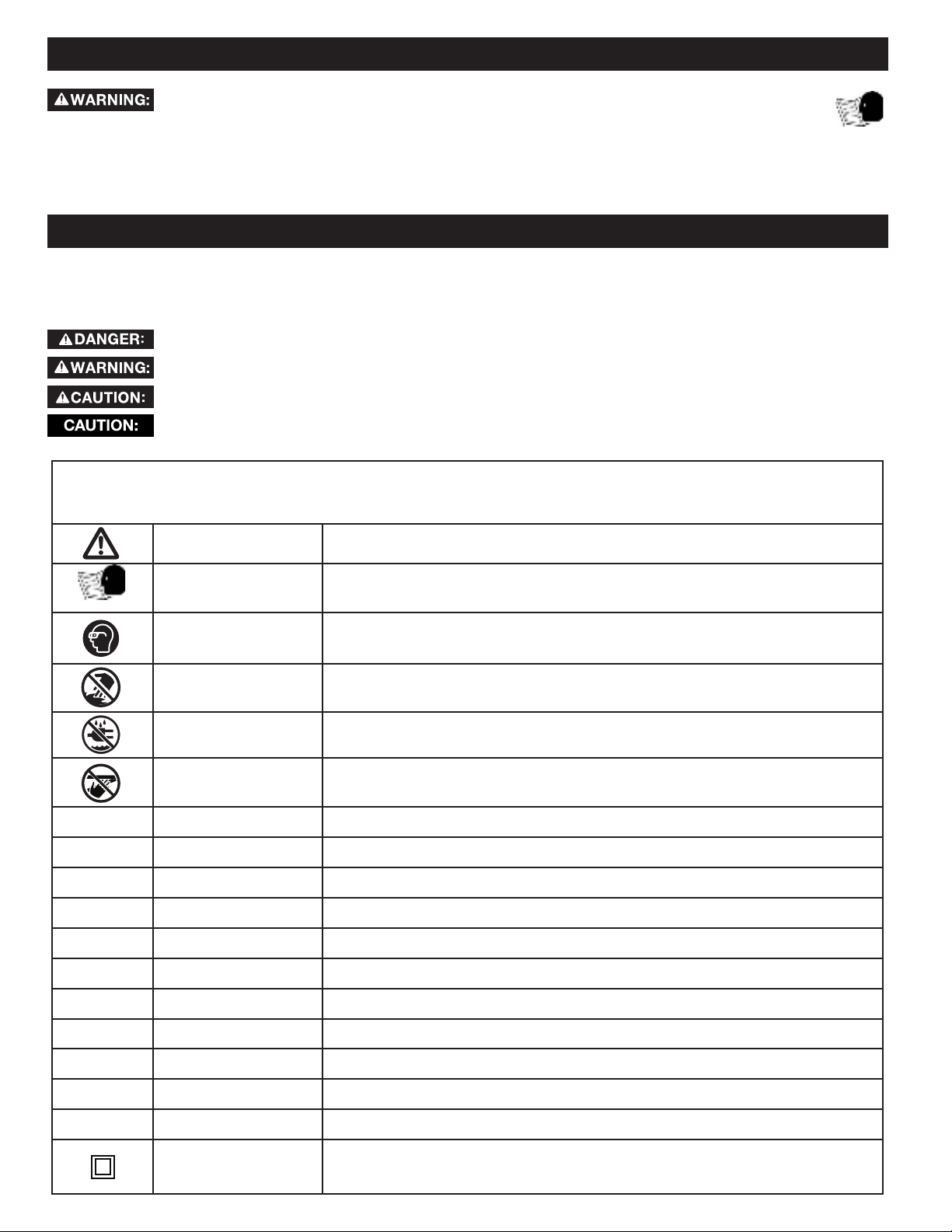
I MPORTANT SAFETY I NSTRUCTI ONS.................................4
SAFETY-SYMBOLS-DEFI NI TI ONS...................................... 4
GENERAL POWER TOOL SAFETY WARNI NGS.................... 5
TABLE SAW SAFETY RULES.................................................6
TERMI NOLOGY ...................................................................6
TABLE SAW SPECI FIC SAFETY RULES...................................6
SAW BLADE GUARD, ANTI-KICKBACK PAWLS AND
RIVING KNI FE.....................................................................8
KI CKBACKS.........................................................................9
PROPOSI TI ON 65 WARNI NG ............................................ 9
POWER CONNECTI ONS ................................................... 10
POWER SOURCE............................................................... 10
EXTENSI ON CORDS........................................................... 10
UNPACKI NG..................................................................... 10
PACKAGE CONTENTS DESCRIPTI ON...................................11
CONTENTS OF HARDWARE BAGS.......................................12
ASSEMBLY.........................................................13
TOOLS NEEDED FOR ASSEMBLY OF ADJUSTMENTS.............13
UNPACKING...................................................................... 13
ASSEMBLING THE STAND .................................... ..............15
HEI GHT ADJUSTMENT KNOB I NSTALLATION ......................16
FENCE ADJUSTMENT KNOB I NSTALLATI ON .. ......................16
INSTALLING THE BLADE....................................................17
THROAT PLATE .................................................................18
ANTI -KI CKBACKS PAWLS ................................................19
BLADE GUARD ................................................................19
INSTALLING THE FENCE..................................... ...............20
REMOVING THE FENCE .....................................................20
ON-BOARD STORAGE.............................................. ..........21
MAKI NG ADJUSTMENTS .................................................. 22
LEVELING THE THROAT PLATE ..........................................22
ADJUSTI NG BLADE PARALLEL TO MITER GAUGE GROOVE
(HEEL) .............................................................................22
SQUARI NG THE BLADE VERTI CALLY TO THE TABLE ............25
ADJUSTI NG THE BEVEL STOPS ..........................................24
ADJUSTI NG THE BLADE HEI GHT........................................25
CHANGING THE BEVEL................................................. .....25
SPECI FI CATI ONS
The RI DGI D®# R4550 10 inch Portable Contractor Table Saw is
designed for portability and high quality performance. It includes:
basic machine, sturdy tubular steel stand, integral 2 1/ 2 inch dust
port, a fence system, T-slot miter gauge, 15 amp motor, on/o
switch, cast aluminum table, extension wing, see-through blade
guard with anti-kickback pawls, and 10 inch carbide blade.
NOTI CE: The manual cover illustrates the current production
model. All other illustrations contained in the manual are
representative only and may not be exact depictions of the actual
labeling or accessories included. They are intended for illustrative
purposes only.
Max depth of cut at 90°: 3 ½ inch
Max depth of cut at 45°: 2 ½ inch
Max rip to right of blade: 32.5 inch
Max rip to left of blade: 22 inch
MOTOR SPECI FI CATI ONS:
Amps 15 inch
Voltage 120 volts
Blade Diameter 10 inch
No Load RPM 5,000
USING THE MI TER GAUGE.................................................25
ADJUSTI NG THE RAI L SYSTEM ..........................................25
USING COLOR CODED SCALES...........................................26
ENGAGING THE FLIP DOWN FENCE ...................................27
RIVING KNI FE HEI GHT SETTI NGS......................................28
RI VI NG KNI FE POSI TI ON AND ALI GNMENT.................28
PARALLEL ALI GNMENT ......................................................29
HORI ZONTAL ALIGNMENT .................................................29
VERTI CAL ALI GNMENT ......................................................29
OPERATI ON......................................................................30
DUST COLLECTION ...........................................................30
TURNI NG THE SAW ON AND OFF.......................................31
TRANSPORTING THE SAW .................................................31
MAKI NG CUTS...................................................................32
RIP CUTS .........................................................................33
BEVEL RIPPING.................................................................33
CROSSCUTTI NG................................................................34
BEVEL CROSSCUTTI NG......................................................34
MITER CUTS.....................................................................34
COMPOUND MI TER CUTS ..................................................35
LARGE PANEL CUTS ..........................................................35
NON-THROUGH CUTS........................................................35
MAKI NG A NON-THROUGH CUT .........................................35
CUTTI NG AI DS AND ACCESSORI ES..................................36
PUSH STICK .....................................................................36
AUXILIARY MITER GAUGE FACING.....................................36
AUXILIARY FENCE (FLIP DOWN) ........................................37
PUSH BLOCK ....................................................................37
GROOVING AND RABBETI NG.............................................37
FEATHERBOARD ...............................................................38
CUT OFF GAUGE ...............................................................38
JIGS.................................................................................38
MAI NTENANCE.......................................................39
KEEP MACHINE CLEAN ......................................................39
MAINTENANCE REMINDERS...............................................39
ACCESSORI ES..................................................40
TROUBLESHOOTI NG.............................................40
PARTS, SERVI CE OR WARRANTY ASSI STANCE............... 41
This tool can ONLY be used w ith woodw orking saw blades.
2

Back View
F5
F6
F7
F8
F9
F10
F11
F12
F13
F14
F15
F16
F17
F18
F19
F9
F10
F11
F12
F13
F14
F15
F16
On Board Storage
Height Adjustment Wheel Knob
Height Adjustment Handwheel
Bevel Lock Lever
Stand
On/O Switch
Saw Body
F17
F18
F19
Rails
Miter Gauge
Riving Knife
Anti-Kickback Pawls
Dust Chute
F1 F2 F3 F4
F5
F6
F7
F8
F1
F2
F3
F4
Blade Guard
Throat Plate
Extension Wing
Rip Fence
Push Stick
Extension Lock
Bevel Scale
FEATURES
3

Some of the following symbols may be used on the tool. Please study them and learn their meaning. Proper interpretation on these
symbols will allow you to operate the tool better and safer.
SYMBOL NAME DESI GNATI ON/ EXPLANATI ON
Safety Alert Indicates a potential personal injury hazard.
Read Operator's Manual To reduce the risk of injury, user must read and understand operator's manual before
using this product.
Eye Protection Always wear eye protection with side shields marked to comply with ANSI Z87.1.
No Hands Symbol Failure to keep your hands away from the blade will result in serious personal injury.
Wet Conditions Alert Do not expose to rain or use in damp locations.
Pinch Warning Always watch for movement paying extra attention to potential areas where pinching
could occur.
V Volts Voltage
A Amperes Current
Hz Hertz Frequency (cycles per second)
min Minutes Time
~ / AC Alternating Current Type of current
ⁿ₀No Load Speed Rotational speed, at no load
.../min Per Minute Revolutions, strokes, surface speed, orbits, etc., per minute
Lbs Pounds Unit of weight
Kg Kilograms Unit of weight
RPM Revolutions Per Minute Speed of rotation of machine
PH:1 Phase 1 This is a 1 phase motor
Double I nsulation
To reduce the risk of electric shock, this equipment has a polarized plug (one blade is wider than the
other). This plug will t in a polarized outlet only one way. If the plug does not t fully in the outlet,
reverse the plug. If it still does not t, contact a qualied electrician to install the proper outlet. DO
NOT change the plug in any way.
I MPORTANT SAFETY I NSTRUCTI ONS
If you have any questions or concerns regarding the use of your tool or the contents of this manual, please stop using the tool and contact
Customer Service, at RI DGID®Portable and Fixed Power Tool Technical Service at (toll free) 1-888-359-4778.
SAFETY SYMBOLS - DEFI NI TI ONS
This manual contains information that is important for you to know and understand. This information relates to protecting YOUR SAFETY
and PREVENTING EQUIPMENT PROBLEMS. To help you recognize this information, we use the symbols below. Please read the manual
and pay attention to these sections.
Indicates an imminently hazardous situation which, if not avoided, will result in death or serious injury.
Indicates a potentially hazardous situation which, if not avoided, could result in death or serious injury.
Indicates a potentially hazardous situation which, if not avoided, may result in minor or moderate injury.
Used without the safety alert symbol indicates potentially hazardous situation which, if not avoided, may result in
property damage.
CAREFULLY READ AND FOLLOW ALL WARNI NGS AND I NSTRUCTI ONS ON YOUR PRODUCT
AND I N THI S MANUAL. SAVE THI S MANUAL. MAKE SURE ALL USERS ARE FAMI LI AR WI TH I TS
WARNI NGS AND I NSTRUCTI ONS WHEN USI NG THE TOOL. I mproper operation, maintenance or modification of tools
or equipment could result in serious injury and/or property damage.
4

The term “power tool” in the warnings refers to your mains-operated (corded) power tool or BATTERY-operated (cordless) power tool.
1. Work area safety
a. Keep work area clean and well-lit. Cluttered or dark areas invite accidents
b. Do not operate power tools in explosive atmospheres, such as in the presence of ammable liquids, gases or dust. Power
tools create sparks which may ignite the dust or fumes.
c. Keep children and bystanders aw ay while operating a power tool. Distractions can cause you to lose control.
2. Electrical safety
a. Power tool plugs must match the outlet. Never modify the plug in any way. Do not use any adapter w ith earthed
( grounded) pow er t ools. Unmodied plugs and matching outlets will reduce risk of electric shock
b. Avoid body contact w ith earthed or grounded surfaces, such as pipes, radiators, ranges and refrigerators. There is an
increased risk of electric shock if your body is earthed or grounded.
c. Do not expose pow er tools to rain or wet conditions. Water entering a power tool will increase the risk of electric shock.
d. Do not abuse the cord. Never use the cord for carrying, pulling or unplugging the power tool. Keep cord away from heat,
oil, sharp edges or moving parts. Damaged or entangled cords increase the risk of electric shock.
e. When operating a power tool outdoors, use an extension cord suitable for outdoor use. Use of a cord suitable for outdoor use
reduces the risk of electric shock.
f. I f operat ing a pow er t ool in a damp location is unavoidable, use a ground fault circuit interrupter ( GFCI ) protect ed supply.
Use of an GFCI reduces the risk of electric shock.
3. Personal safety
a. Stay alert, w atch what you are doing and use common sense w hen operating a power tool. Do not use a power tool while
you are tired or under the inuence of drugs, alcohol or medication. A moment of inattention while operating power tools may
result in serious personal injury.
b. Use personal protective equipment. Always wear eye protection. Protective equipment such as dust mask, non-skid safety shoes,
hard hat, or hearing protection used for appropriate conditions will reduce personal injuries.
c. Prevent unintentional starting. Ensure the switch is in the o-position before connection to power source, picking up, or
carrying the tool. Carrying power tools with your nger on the switch or energising power tools that have the switch on invites accidents.
d. Remove any adjusting key or w rench before turning the power tool on. A wrench or a key left attached to a rotating part of the
power tool may result in personal injury.
e. Do not overreach. Keep proper footing and balance at all times. This enables better control of the power tool in unexpected
situations
f. Dress properly. Do not w ear loose clothing or jewelery. Keep your hair, clothing and gloves away from moving parts.
Loose clothes, jewelery or long hair can be caught in moving parts.
g. I f devices are provided for the connection of dust extraction and collection facilities, ensure these are connected and
properly used. Use of dust collection can reduce dust-related hazards.
h. Do not let familiarity gained from frequent use of tools allow you to become complacent and ignore tool safety principles.
A careless action can cause severe injury within a fraction of a second.
4. Power tool use and care
a. Do not force the pow er tool. Use the correct power tool for you application. The correct power tool will do the job better and
safer at the rate for which it was designed.
b. Do not use the power tool if the switch does not turn it on and o. Any power tool that cannot be controlled with the switch is
dangerous and must be repaired.
c. Disconnect the plug from the power source before making any adjustments, changing accessories, or storing power tools.
Such preventive safety measures reduce the risk of starting the power tool accidentally.
d. Store idle power tools out of the reach of children and do not allow persons unfamiliar with the power tool or these
instructions to operate the power tool. Power tools are dangerous in the hands of untrained users.
e. Maintain power tools and accessories. Check for misalignment or binding of moving parts , breakage of parts and any
other condition that may aect the power tool’s operation. If damaged, have the power tool repaired before use. Many
accidents are caused by poorly maintained power tools.
f. Keep cutting tools sharp and clean. Properly maintained cutting tools with sharp cutting edges are less likely to bind and are easier to
control.
g. Use the power tool, accessories and tools bits etc. in accordance with these instructions, taking into account the working
conditions and the w ork to be performed. Use of the power tool for operations dierent from those intended could result in a
hazardous situation.
h. Keep handles and grasping surfaces dry, clean and free from oil and grease. Slippery handles and grasping surfaces do not allow
for safe handling and control of the tool in unexpected situations.
5. Service
a. Have your power tool serviced by a qualied repair person using only identical replacement parts. This will ensure that the
safety of the power tool is maintained.
GENERAL POWER TOOL SAFETY WARNI NGS
Read all safety warnings, instructions, illustrations and specications provided with this power tool.
Failure to follow all instructions listed below may result in electric shock, re and/or serious injury.
Save all w arnings and instructions for future reference.
5

Failure to follow these rules may result in serious personal injury.
TABLE SAW SPECI FI C SAFETY RULES
WARNING READ ALL SAFETY WARNINGS DESIGNATED BY THE SYMBOL AND ALL I NSTRUCTI ONS.
1. GUARDI NG RELATED WARNI NGS ( FOR TABLE SAW, UL 62841-3-1)
a. Keep guards in place. Guards must be in working order and be properly mounted. A guard that is loose,
damaged, or is not functioning correctly must be repaired or replaced.
b. Alw ays use saw blade guard, riving knife and anti-kickback device for every through-cutting operation. For
through-cutting operations where the saw blade cuts completely through the thickness of the workpiece, the guard and
other safety devices help reduce the risk of injury.
c. I mmediately reattach the guarding system after completing an operation ( such as rabbeting or resawing
cuts) which requires removal of the guard, riving knife and/or anti-kickback device. The guard, riving knife,
and anti-kickback device help to reduce the risk of injury.
d. Make sure the saw blade is not contacting the guard, riving knife or the workpiece before the sw itch is
turned on. I nadvertent contact of these items with the saw blade could cause a hazardous condition.
e. Adjust the riving knife as described in this instruction manual. Incorrect spacing, positioning and alignment can
make the riving knife ineective in reducing the likelihood of kickback.
f. For the riving knife and anti-kickback device to w ork, they must be engaged in the w orkpiece. The riving
knife and anti-kickback device are ineective when cutting workpieces that are too short to be engaged with the riving
knife and anti-kickback device. Under these conditions a kickback cannot be prevented by the riving knife and antikickback
device.
g. Use the appropriate saw blade for the riving knife. For the riving knife to function properly, the saw blade diameter
must match the appropriate riving knife and the body of the saw blade must be thinner than the thickness of the riving
knife and kerf of the saw blade must be wider than the thickness of the riving knife.
2. CUTTI NG PROCEDURES WARNI NGS
a. DANGER: Never place your ngers or hands in the vicinity or in line with the saw blade. A moment of
inattention or a slip could direct your hand towards the saw blade and result in serious personal injury.
b. Feed the w orkpiece into the saw blade or cutter only against the direction of rotation. Feeding the workpiece
in the same direction that the saw blade is rotating above the table may result in the workpiece, and your hand, being
pulled into the saw blade.
TABLE SAW SAFETY RULES
Failure to follow these rules may result in serious personal injury.
SEE GENERAL POWER TOOL SAFETY SECTI ON OF THI S MANUAL. Read entire instruction manual before operating saw. Learning
the saw’s proper applications, limitations, and specic potential hazards will greatly minimize the possibility of accidents and injury. Make
sure all users are familiar with its warnings and instructions before using saw.
SEE POWER CONNECTI ON SECTI ON OF THI S MANUAL for instructions and warnings regarding power cords and connections.
• Through-cut – Any cut that completely cuts through the
workpiece.
• Non-through cut – Any cut that does not completely cut
through the workpiece.
• Push stick – A wooden or plastic stick, usually homemade,
that is used to push a small workpiece through the saw and
keeps the operator’s hands clear of the blade.
• Kickback – Occurs when the saw blade binds in the cut or
between the blade and the fence and thrusts the workpiece
back toward the operator or lowering the workpiece down to
the blade.
• Re-saw ing – Flipping material to make a cut the saw is not
capable of making in one pass.
• Cove cutting – Also known as coving, cove cutting is an
operation where the work is fed at an angle across the
blade. NOTE: This can be a dangerous operation and is not
recommended.
• Freehand – Cutting without the use of a miter gauge or
rip fence or any other means of guiding or holding the
workpiece other than the operator’s hand. NOTE: This can be
a dangerous operation and is not recommended.
• Plunge cutting – Blind cuts in the workpiece made by either
raising the blade through the workpiece. NOTE: This can be a
dangerous operation and is not recommended.
• Rabbet Cut - A cut on the end or face (edge) of a board -
the extruding piece is the tongue.
• Kerf - A cut or incision made by a saw.
TERMI NOLOGY
The following terms will be used throughout the manual and you should become familiar with them.
6

TABLE SAW SAFETY RULES
c. Never use the mitre gauge to feed the w orkpiece when ripping and do not use the rip fence as a length stop
when cross cutting w ith the miter gauge. Guiding the workpiece with the rip fence and the mitre gauge at the same
time increases the likelihood of saw blade binding and kickback.
d. When ripping, always apply the w orkpiece feeding force between the fence and the saw blade. Use a push
stick when the distance between the fence and the saw blade is less than 150mm, and use a push block when this
distance is less than 50mm. "Work helping" devices will keep your hand at a safe distance from the saw blade.
e. Use only the push stick provided by the manufacturer or constructed in accordance with the instructions.
This push stick provides sucient distance of the hand from the saw blade.
f. Never use a damaged or cut push stick. A damaged push stick may break causing your hand to slip into the saw
blade.
g. Do not perform any operation "freehand". Always use either the rip fence or the mitre gauge to position and guide
the workpiece. "Freehand" means using your hands to support or guide the workpiece, in lieu of a rip fence or mitre
gauge. Freehand sawing leads to misalignment, binding and kickback.
h. Never reach around or over a rotating saw blade. Reaching for a workpiece may lead to accidental contact with the
moving saw blade.
i. Provide auxiliary workpiece support to the rear and/ or sides of the saw table for long and/ or w ide
workpieces to keep them level. A long and/ or wide workpiece has a tendency t o pivot on the table’s edge, causing
loss of control, saw blade binding and kickback.
j. Feed w orkpiece at an even pace. Do not bend or tw ist the workpiece. If jamming occurs, turn the tool o
immediately, unplug the tool then clear the jam. Jamming the saw blade by the workpiece can cause kickback or stall the
motor.
k. Do not remove pieces of cut-o material while the saw is running. The material may become trapped between
the fence or inside the saw blade guard and the saw blade pulling your ngers into the saw blade. Turn the saw o and
wait until the saw blade stops before removing material.
l. Use an auxiliary fence in contact with the table top when ripping w orkpieces less than 2mm thick. A thin
workpiece may wedge under the rip fence and create a kickback.
m. Never Cut Metals, Cement Board or Masonry. Certain man-made materials have special instructions for cutting on
table saws. Follow the manufacturer’s recommendations at all times too avoid overheating the saw blade tips as well as
melting the plastic. Avoid overheating blade tips by pushing material through blade evenly. Forcing material to fast can
cause heating and damage to blade or workpiece. If cutting plastics is permitted, cut at a slower pace to avoid melting the
plastic.
3. Kickback causes and related warnings
Kickback is a sudden reaction of the workpiece due to a pinched, jammed saw blade or misaligned line of cut in the workpiece
with respect to the saw blade or when a part of the workpiece binds between the saw blade and the rip fence or other xed
object.
a. Most frequently during kickback, the workpiece is lifted from the table by the rear portion of the saw blade and
is propelled towards the operator. Kickback is the result of saw misuse and/ or incorrect operating procedures or conditions
and can be avoided by taking proper precautions as given below.
b. Never stand directly in line with the saw blade. Always position your body on the same side of the saw blade as
the fence. Kickback may propel the workpiece at high velocity towards anyone standing in front and in line with the saw
blade.
c. Never reach over or in back of the saw blade to pull or to support the workpiece. Accidental contact with the
saw blade may occur or kickback may drag your ngers into the saw blade.
d. Never hold and press the workpiece that is being cut o against the rotating saw blade. Pressing the
workpiece being cut o against the saw blade will create a binding condition and kickback.
e. Align the fence to be parallel w ith the saw blade. A misaligned fence will pinch the workpiece against the saw blade
and create kickback.
f. Use a featherboard to guide the workpiece against the table and fence when making non-through cuts such
as rabbeting, or resawing cuts. A featherboard helps to control the workpiece in the event of a kickback.
g. Use extra caution w hen making a cut into blind areas of assembled workpieces. The protruding saw blade may
cut objects that can cause kickback.
h. Support large panels to minimise the risk of saw blade pinching and kickback. Large panels tend to sag under
their own weight. Support(s) must be placed under all portions of the panel overhanging the table top.
i. Use extra caution when cutting a w orkpiece that is tw isted, knotted, warped or does not have a straight
edge to guide it with a mitre gauge or along the fence. A warped, knotted, or twisted workpiece is unstable and
causes misalignment of the kerf with the saw blade, binding and kickback.
j. Never cut more than one w orkpiece, stacked vertically or horizontally. The saw blade could pick up one or more
pieces and cause kickback.
7

SAW BLADE GUARD, ANTI -KI CKBACK PAWLS AND RI VI NG KNI FE
ASSEMBLY
Your table saw is equipped with a blade guard, anti-kickback
pawls and riving knife assembly that covers the blade and reduces
the possibility of accidental blade contact.
The riving knife is a flat plate that fits into the cut made by
the saw blade and effectively fights kickback by lessening the
tendency of the blade to bind in the cut.
Two anti-kickback pawls are located on the sides of the riving
knife that allow the wood to pass through the blade in the cutting
direction but reduce the possibility of the material being thrown
backwards toward the operator.
The blade guard and anti-kickback pawls can ONLY be used
when making through cuts that sever the wood. When making
rabbets and other non-through cuts, the blade guard and anti-
kickback pawls MUST be removed and riving knife lowered to the
non-through cut position marked on the riving knife.
Use all components of the guarding system (blade guard
assembly, riving knife and anti-kickback pawls) for every
operation for which they can be used including all through-
cutting. I f you elect not to use any of these components for
a particular application, exercise additional caution regarding
control of the workpiece, the use of push sticks, the position of
your hands relative to the blade, the use of safety glasses, the
means to avoid kickback and all other warnings contained in this
manual and on the saw itself. Replace the guarding systems as
soon as you return to through-cutting operations. Keep the guard
assembly in working order.
TABLE SAW SAFETY RULES
k. When restarting the saw w ith the saw blade in the w orkpiece, centre the saw blade in the kerf so that the
saw teeth are not engaged in the material. I f the saw blade binds, it may lift up the workpiece and cause kickback
when the saw is restarted.
l. Keep saw blades clean, sharp, and with sucient set. Never use warped saw blades or saw blades with cracked or
broken teeth. Sharp and properly set saw blades minimize binding, stalling and kickback.
4. Table saw operating procedure warnings
a. Turn o the table saw and disconnect the power cord when removing the table insert, changing the saw
blade or making adjustments to the riving knife, any kickback device or saw blade guard, and when the
machine is left unattended. Precautionary measures will avoid accidents.
b. Never leave the table saw running unattended. Turn it o and don’t leave the tool until it comes to a complete stop.
An unattended running saw is an uncontrolled hazard.
c. Locate the table saw in a well-lit and level area where you can maintain good footing and balance. I t should
be installed in an area that provides enough room to easily handle the size of your workpiece. Cramped, dark areas, and
uneven slippery oors invite accidents.
d. Frequently clean and remove sawdust from under the saw table and/or the dust collection device.
Accumulated sawdust is combustible and may self-ignite.
e. The table saw must be secured. A table saw that is not properly secured may move or tip over.
f. Remove tools, wood scraps, etc. from the table before the table saw is turned on. Distraction or a potential jam
can be dangerous.
g. Alw ays use saw blades w it h correct size and shape ( diamond versus round) of arbor holes. Saw blades that
do not match the mounting hardware of the saw will run o-center, causing loss of control.
h. Never use damaged or incorrect saw blade mounting means such as anges, saw blade washers, bolts or
nuts. These mounting means were specially designed for your saw, for safe operation and optimum performance.
i. Never stand on the table saw, do not use it as a stepping stool. Serious injury could occur if the tool is tipped or if
the cutting tool is accidentally contacted.
j. Make sure that the saw blade is installed to rotate in the proper direction. Do not use grinding wheels, wire
brushes, or abrasive wheels on a table saw. I mproper saw blade installation or use of accessories not recommended may
cause serious injury.
k. DO NOT REMOVE A WORKPI ECE that is damaged or jammed without rst turning o the saw and unplugging it from
the power source.
8

KI CKBACKS
Kickbacks can cause serious injury. A kickback occurs when a part
of the workpiece binds between the saw blade and the rip fence,
or other fixed object, and rises from the table and is thrown
toward the operator. Kickbacks can be avoided by attention to the
following conditions.
HOW TO REDUCE THE RI SK OF KI CKBACKS AND PROTECT
YOURSELF FROM POSSI BLE I NJURY:
Be certain that the rip fence is parallel to the saw blade.
DO NOT rip by applying the feed force to the section of the
workpiece that will become the cut-off (free) piece. Feed force
when ripping should ALWAYS be applied between the saw
blade and the fence; use a push stick for narrow work, 6 inches
(150mm) wide or less.
Keep saw blade guard, riving knife and anti-kickback assembly
in place and operating properly. The riving knife MUST be in
alignment with the saw blade and the anti-kickback assembly
MUST stop a kickback once it has started. Check their action
before ripping by pushing the wood under the anti-kickback
assembly. The teeth MUST prevent the wood from being pulled
toward the front of the saw. If any part of assembly is not
operational, return to the nearest authorized service center for
repair.
Plastic and composite materials (like hardboard) may be cut
on your saw. However, since these are usually quite hard and
slippery, the anti-kickback pawls may not stop a kickback.
Therefore, be especially attentive to following proper set up and
cutting procedures for ripping.
Use saw blade guard, anti-kickback pawls, and riving knife
assembly for every possible operation, including all through-cut
sawing.
Push the workpiece past the saw blade prior to releasing control.
NEVER rip a workpiece that is twisted or warped, or does not
have a straight edge to guide along the fence.
NEVER saw a large workpiece that cannot be controlled.
NEVER use the fence as a guide or length stop when
crosscutting.
NEVER saw a workpiece with loose knots, flaws, nails or other
foreign objects.
NEVER rip a workpiece shorter than 10 inches (254mm).
NEVER use a dull blade. A dull blade should be replaced or
re-sharpened.
PROPOSI TI ON 65 WARNI NG:
SAVE THESE I NSTRUCTI ONS.
Refer to them often and use them to instruct others. • I f tool is loaned to someone, also loan
them these instructions.
Dust created by power sanding, sawing, grinding, drilling, and other construction activities may contain chemicals
known to the state of California to cause cancer, birth defects or other reproductive harm. Some examples are:
• Lead from lead-based paints
• Crystalline silica from bricks and cement and other masonry products
• Asbestos dust
• Arsenic and chromium from chemically-treated lumber
Your risk from these exposures varies depending on how often you do this type of work. To reduce your exposure to these chemicals:
work in a well-ventilated area and work with approved safety equipment, such as dust masks that are specically designed to lter out
microscopic particles.
Avoid prolonged contact with dust from power sanding, sawing, grinding, drilling, and other construction activities.
Wear protective clothing and wash exposed areas with soap and water.
TABLE SAW SAFETY RULES
9

* * Ampere rat ing ( on tool data label)
12A- 16A
Cord Length Wire Size
25' 14 AWG
50' 12 AWG
* * Used on 12 gauge - 20 amp circuit
NOTE: AWG = American Wire Gauge
POWER CONNECTI ONS
POWER SOURCE
This saw is equipped with a 15-amp motor for use with a 120-
volt, 60-HZ alternating current.
For voltage, the wiring in a shop is as important as the motor’s
rating. A line intended only for lights may not be able to properly
carry the current needed for a power tool motor; wire that is
heavy enough for a short distance may be too light for a greater
distance; and a line that can support one power tool may not be
able to support two or three. A separate electrical circuit should
be used for your machines. This circuit should not be less than
# 12 wire and should be protected with a 20-amp time lag fuse
and/ or circuit breaker. I f an extension cord is used, use ONLY
3-wire extension cords which have 3-prong grounding-type plugs
and matching receptacle which will accept the machine’s plug.
Before connecting the machine to the power line, make sure
the switch is in the “OFF” position and be sure that the electric
current is of the same characteristics as indicated on the machine.
A substantial voltage drop will cause a loss of power and overheat
the motor. It may also damage the machine.
DO NOT EXPOSE THE MACHI NE TO RAI N OR OPERATE THE MACHI NE I N DAMP LOCATI ONS.
KEEP the extension cord clear of the work area. Position the cord so it will not get caught on lumber, tools or other
obstructions
• Use proper extension cords. Make sure your extension cord is a 3-wire extension cord which has a 3-prong grounding type plug and
matching receptacle which will accept the machine’s plug. When using an extension cord, be sure to use one heavy enough to carry
the current of the machine. An undersized cord will cause a drop in line voltage, resulting in loss of power and overheating. The
table below shows the maximum gauge to use depending on the cord length. I f in doubt, use the next heavier gauge. The smaller
the gauge number, the heavier the cord. ONLY round, jacketed cords listed by Underwriter’s Laboratories (UL) should be used.
NEVER use a damaged extension cord. Check extension cords before each use. I f damaged, replace immediately.
Touching the damaged area could cause electrical shock resulting in serious injury.
I N ALL CASES, MAKE CERTAI N THE RECEPTACLE I N QUESTI ON I S PROPERLY GROUNDED. I F YOU ARE
NOT SURE, HAVE A QUALI FI ED ELECTRI CI AN CHECK THE RECEPTACLE.
EXTENSI ON CORDS
UNPACKI NG
• Use a safety strap to avoid tip over when lifting machine.
• Prior to tool assembly and use, read this manual thoroughly
to familiarize yourself with proper assembly, maintenance and
safety procedures.
Check shipping carton and machine for damage before unpacking.
Carefully remove components in top foam layer and then
remove the top layer of foam. Lay out all parts on a piece of
cardboard or other clean, flat surface. THE SAW STAND WI LL
BE ASSEMBLED TO THE SAW BODY AS I T I S I N THE
BOX. THE SAW BODY WI LL NOT NEED TO BE REMOVED
UNTI L THE STAND I S COMPLETED AND ATTACHED TO THE
UNDERSI DE OF THE SAW. ALWAYS check for and remove
protective shipping materials around motors and moving parts.
DO NOT discard shipping carton and packing materials until you
have carefully inspected the contents, assembled the machine
and are satisfied that it operates correctly.
Compare package contents to Component Parts List and
Hardware Package List prior to assembly to make sure all items
are present. Carefully inspect parts to make sure no damage
occurred during shipping. I f any parts are missing, damaged
or pre-assembled, DO NOT assemble. I nstead, call RI DGID®
Customer Service at (toll free) 1-888-359-4778.
After assembly remove any protective materials and coatings from
all of the parts and the table saw. The protective coatings can be
removed by spraying WD-40®on them and wiping them off with a
soft cloth. This may need to be redone several times before all of
the protective coatings are removed completely.
10

PACKAGE CONTENTS DESCRI PTI ON
Saw Body
Stand Handle
Pedal Assembly
Upper Stand Assembly
Right Support Tube
10 inch Carbide Tipped Blade
Miter Gauge
Push Stick
Left Support Tube
Fence
Blade Guard Assembly
Anti-Kickback Pawls
Wheels (2)
Support Spreader Bar
Throat Plate
Open End Blade Wrench
Closed End Blade Wrench
Support Rod Connection Base
UNPACKI NG
PC1
PC2
PC3
PC17
PC18
PC4
PC5
PC6
PC7
PC8
PC9
PC10
PC11
PC12
PC13
PC14
PC16
PC15
PC1
PC5
PC9
PC13
PC18
PC17
PC3
PC7
PC11
PC15
PC4
PC8
PC12
PC16
PC2
PC6
PC10
PC14
11

UNPACKI NG
CONTENTS OF HARDWARE BAGS
HP1
HP1
HP6
HP5
HP2
HP2
HP7
HP4
HP9
HP4
HP3
HP3
HP8
HP5
HP10
HP11
HP6 HP7 HP8 HP9 HP10 HP11
M6 x 50mm (1 15/ 16 inch) Hex Bolt (2)
Plastic Spacer (8)
M8 Locknut (12)
M8 x 75mm (2 15/ 16 inch) Carriage Screw (4)
M8 x 37mm (1 15/ 32 inch) Carriage Screw (4)
Wheel Handle Shoulder Screw
005890
003578
003380
003570
003640
006459
004306
006462
005929
004374
003579
Height Adjustment Wheel Knob
Combination 4mm Allen Wrench / Phillips Screwdriver
Fence Adjustments Knob
M6 X 25L Hex Socket Round Head Screw
Flat Washer 6mm x 14mm x 1T
12

ASSEMBLY
• Assemble stand with saw upside down in box, then stand for
nal assembly.
• Stand assembly is an integral and necessary part of the
Support Structure for this Saw.
• DO NOT modify Saw, use or create Accessories not
recommended for use with this Saw.
• Make sure Power Switch is in “OFF” position before
connecting to Power Supply. DO NOT connect to power
supply until assembly is complete.
• Avoid contact with Blade Teeth. Keep Blade stored or
lowered when possible.
UNPACKI NG
1. Remove upper Packing Tray and its components.
2. Cut sides of Box at all four corners. See Figure 1. Leave the
saw body upside down in packaging and proceed to next
page with assembling the sub-components.
Figure 1
TOOLS NEEDED FOR ASSEMBLY OR ADJUSTMENTS.
Straight Edge Combination Square
3mm Hex Key 5mm Hex Key 13mm Combination Wrench
13

ASSEMBLY
ASSEMBLI NG THE STAND
1. First remove Nut and outer Washer on each side of the
Pedal Assembly PC3 . Then attach the Wheels and place the
Washer and Nut back on each side, as shown in Figure 2 .
Be sure not to over-tighten the Nut.
NOTE: The hardware to attach the Wheels will NOT be found with
additional Hardware. Hardware for this is attached to the Pedal
Assembly PC3 . Check orientation of Wheels and if Wheels rub
against Frame, reverse orientation. Set Wheel Assembly aside for
later use.
Figure 2
Figure 3
Figure 4
Figure 5
PC3
HP1
PC14
NUT
PC13
WASHER
1/ 2 inch or
13mm w rench
3. Attach Support Rod Connection Base PC18 into the Upper
Stand Assembly from Figure 3 Secure with M8 x 35mm.
Carriage Screw HP5 and M8 Locknut HP3 . See Figure 4.
NOTE: The Feet on the Support Rod Connection Base PC18 should
face to the outside (left).
4. Secure Upper Stand Assembly PC4 to Upper Stand Support
(pre-attached to Saw) with M8 x 75mm Carriage
Screw HP4 , Plastic Spacer HP2 , and M8 Locknut HP3 . See
Figure 5.
PC9
PC4
HP2
PC18
PC5
HP3
HP5
HP3
HP4
2. Connect the Support Spreader Bar PC14 to Left Support
Tube PC9 and Right Support Tube PC5 with
M6 x 50mm Hex Bolts HP1 . See in Figure 3.
14

ASSEMBLY
5. With Table saw still in Lower Packing Tray, attach Stand
Handle PC2 to Tubular Base of Saw with M8x35mm
Carriage Screw HP5 and M8 Locknut HP3 . See Figure 6.
NOTE: Square and round holes can be aligned together.
Figure 6
Figure 7
Figure 8
PC2
6. Attach Leg Assembly to the Upper Leg Assembly. I nsert
Plastic Spacer HP2 between Legs and secure with
M8 x 75mm Carriage Screw HP4 and M8 Locknut HP3 . See
Figure 7.
7. I nstall the Wheel Assembly from Figure 2 to Leg Assembly
installed in Figure 7. I nsert Plastic Spacer HP2 between
Legs and secure with M8 x 75mm Carriage Screw HP4 and
M8 Locknut HP3 . See Figure 8.
HP3
HP3
HP2
HP2
HP3
HP5
HP4
HP4
8. Raise the Wheel Assembly part of the Stand to help align
the holes with the Leg Assembly. Insert Plastic Spacer HP5
between Legs and secure with M8 x 75mm Carriage Screw
HP4 and M8 Locknut HP3 .
NOTE: DO NOT over-tighten. Cut zip tie securing Pedal. See
Figure 9.
Figure 9
HP3
HP5
HP4
15

ASSEMBLY
2
1
Figure 10
Figure 11
9. Unlock the Bevel Lock and rotate the Motor Assembly
enough to remove the Shipping Foam protecting the Saw
Motor as shown in Figure 10.
10. Once the saw is upright disengage the pedal, push down
on the handles until the catch is engaged, and then
continue the remaining assembly steps.
HEI GHT ADJUSTMENT KNOB
I NSTALLATI ON
1. I nsert Wheel Handle Shoulder Screw HP6 into Height
Adjustment Wheel Knob HP7 as shown in Figure 12.
2. Tighten Shoulder Screw with Combination 4mm Allen
Wrench/ Phillips Screwdriver HP8 or Phillips Screw Driver
into the Hand Wheel. Height Adjustment Wheel Knob
should rotate freely around Shoulder Screw when raising or
lowering the blade with the Height Adjustment Hand
Wheel.
FENCE ADJUSTMENT KNOB
I NSTALLATI ON
1. I nsert and tighten Hex Socket screw HP10 through Flat
Washer HP11 , into Fence Adjustments Knob HP9 as shown in
Figure 13. Make sure the groove in the knob aligns with the
rib on the pinion.
Figure 12
Figure 13
HP6
HP7
HP10
HP9
HP11
16

ASSEMBLY
I NSTALLI NG THE BLADE
1. Raise the Motor/ Arbor Assembly to the upper most posit ion
to provide easy access to Riving Knife Lock Lever and
Arbor Assembly.
2. Ensure Riving Knife Lock Lever is in unlock position. See
Figure 14.
3. Detach the on-board Wrenches located on the right side of
the Saw by loosening and removing M8 Wing Nut.
4. Place the Open End Wrench PC16 on the Spindle Shoulder
between the Arbor Flange and I nner Flange.
5. Place the Closed End Wrench PC17 over the Arbor Nut.
Holding the Spindle Shaft in place, loosen and remove the
Arbor Nut and Arbor Flange. See Figure 14.
NOTE: Use ONLY 10 inch (254mm) diameter Blades with 5/ 8
inch (16mm) Arbor Holes, rated at 5,000 rpm or higher, 0.10 inch
(2.6mm) min. kerf width and 0.073 inch (1.85mm) max body
thickness. ONLY use 10 inch Blades designed for woodcutting.
6. Place Blade PC6 on the Arbor Shaft with the Teeth on the
Blade pointing toward the front of the Saw. Place Outer
Blade Washer Aon Arbor Shaft Bwith the large side
of the Washer against the Blade, then secure Blade
Assembly with Nut C. See Figure 15.
7. Tighten Nut with Blade Wrenches PC16 and PC17 . Open End
Wrench will fit on the Arbor Shaft between the I nner
Flange Washer Dand the Motor Assembly (if necessary,
turn Arbor Shaft to align ats on the Arbor Shaft to the
Wrench). Closed End Wrench will t on the Nut. See Figure
16.
8. Return Blade Wrenches PC16 and PC17 to On-Board Storage
location and secure the M8 Wing Nut. Raise the Riving
Knife in the through cut position prior to installation of
Throat Plate.
Details for positioning the Riving Knife are on page 28 RI VI NG
KNI FE POSI TI ON AND ALI GNMENT Section. See Figure 16.
Figure 14
UNLOCKUNLOCK
POSI TI ONPOSI TI ON
Figure 15
Figure 16
TOOTH
DI RECTI ON
FRONT
OF SAW
PC17
PC16
PC6
A
C
B
PC17
PC16
D
17

ASSEMBLY
1. The Riving Knife MUST be installed for every through cut
and for every non-through cut unless the Riving Knife A
would interfere with the cut.
2. The Riving Knife provided with the table saw shall be
thicker than the body of the matching Saw Blades provided
with the Table Saw but thinner than the kerf width of that
Saw Blade.
3. ALWAYS use a Blade with the correct thickness to match
the Riving Knife. (0.10 inches (2.6mm) min. kerf width and
0.073 inches (1.85mm) max body thickness).
4. The Riving Knife MUST be securely positioned in the up or
through cut position when using the Anti-Kickback Pawls
and Blade Guard.
5. Make sure the Riving Knife is properly aligned to the
Blade. (See page 28 RI VI NG KNI FE POSI TI ON AND
ALI GNMENT Section).
Figure 17
THROUGH CUTTHROUGH CUT
POSI TI ONPOSI TI ON
LOCKLOCK
POSI TI ONPOSI TI ON
Figure 18
Figure 19
PC15
PC15
A
THROAT PLATE
1. To install Throat Plate PC15 , lower Blade below Tabletop,
then carefully feed the Throat Plate, slotted end rst, from
the rear of the Table to the front, keeping the Blade
centered within the slot on the Throat Plate. See Figure 18.
The Throat Plate should rest within the cavity in the
Tabletop.
2. Ensure that the Throat Plate is ush with the top of the
Table.
3. If the Throat Plate is not ush with the Tabletop, adjust the
height of the Throat Plate using the four Set Screws A.
NOTE: For leveling the throat plate see page 22.
4. To remove Throat Plate, lower Blade below Tabletop, then
carefully slide the throat plate out from the front of the
table to the rear, using the cutout on Figure 19.
NOTE: If Throat Plate is not ush with the Table Top the Anti-
Kickback Pawls can interfere with the Blade adjustment.
A
A
A
A
A
A
A
A
To reduce the risk of serious injury,
18

ASSEMBLY
Figure 20
ANTI -KI CKBACK PAWLS AND
BLADE GUARD
ANTI -KI CKBACK PAWLS
To reduce the risk of serious personal injury,
Anti-Kickback Pawls MUST be in place when making a through
cut.
1. Refer to Figure 20 and locate the Anti-Kickback Pawls
mounting slot in the middle of the top edge of the Riving
Knife A.
2. Slide slot in the middle of the Anti-Kickback Pawls
Assembly along the top of the Riving Knife until the Press
Pin Blocates the center slot on the Riving Knife.
3. Depress the Press Pin on the Anti-Kickback Pawls Assembly
PC12 to allow the Assembly to drop into the slot. Push down
on the Anti-Kickback Pawls Assembly until it snaps into
place and locks. Release Press Pin. NOTE: Pull up on the
Anti-Kickback Pawls to make sure it is locked in place.
To remove the Anti-Kickback Pawls, depress the Press Pin and pull
the Anti-Kickback Assembly off the Riving Knife.
PC12
B
A
BLADE GUARD
1. While holding the Blade Guard Assembly PC11 in a vertical
position, hook the Locating Pin Cat the back end of the
Blade Guard Assembly into the slot at the back edge of the
Riving Knife.
2. Rotate the Blade Guard Assembly toward the front of the
saw until Support Arms Dof the Blade Guard Assembly
are parallel to the Table as shown in Figure 21.
3. See Figure 23 (next page). While holding down on the
front of the Support Arms Cpress the Lock Tab Edown
until it snaps into the locked position. Check to make sure
the Guard is locked onto the Riving Knife by pulling on the
guard. If the Guard is not locked, the Lock Tab will ip up
to the unlocked position.
To reduce the risk of serious personal injury,
the Blade Guard MUST be in place when making a through cut.
If the Support Arms Dare not parallel to the table, the Riving
Knife is not in the raised (through-cut) position. Remove Blade
Guard Assembly and Anti-Kickback Pawls and raise Riving Knife,
then re-install the Anti-Kickback Pawls and the Blade Guard
Assembly.
C
A
B
Figure 21
1. I f Blade Guard is not parallel to Table, Riving Knife is not
in raised (through cut) position. Raise and lower each side
of the Blade Guard to verify free movement of the Guard
System. Be sure the Guard System can be raised enough
to clear your workpiece.
Figure 22
D
PC11
C
19

ASSEMBLY
Figure 24
Figure 25
I NSTALLI NG THE FENCE
The fence can be positioned on one of the three pairs of tabs.
Two on the right side of the blade and one on the left side.
1. To engage the fence, hold it at an upward angle while
engaging the desired tab pair into the front and rear fence
notches.
2. Lower the fence until the two latches engage the fence
rails.
See Figure 24 and 25.
REMOVI NG THE FENCE
1. Lift the orange latches Fon the on the sides of the
Fence.
2. Tilt the Fence up at a slight angle.
3. Disengage notches on Fence System from tabs on rail.
See Figure 26. To see Fence installed refer to page 3.
Figure 26
To remove the Blade Guard Assembly:
1. Lift the Lock Tab Eto the unlocked position.
2. Rotate the Guard back and slide the Locating Pin Cfrom
the Riving Knife slot.
See Figure 23.
Figure 23
E
C
F
20
Other manuals for R4550
1
Table of contents
Other RIDGID Saw manuals

RIDGID
RIDGID MS1060 User manual

RIDGID
RIDGID R4091 User manual

RIDGID
RIDGID 550-1 User manual

RIDGID
RIDGID R3020 User manual

RIDGID
RIDGID CM1450 User manual

RIDGID
RIDGID R865 User manual

RIDGID
RIDGID R4113 User manual

RIDGID
RIDGID 5228/530 User manual

RIDGID
RIDGID R4010TR User manual

RIDGID
RIDGID TS3612 User manual