Rieber Varithek-1/1-ik User manual

Operating Instructions
Varithek-1/1-ik, -400-ik
from construction year 2005
[ Universal cooking and
heating units ]
Operating instructions
induction hob
varithek
®
Type: 1/1-ik 3500, 1/1-ik 5000, 400-ik 3500 und 400-ik 5000
Please read carefully before use
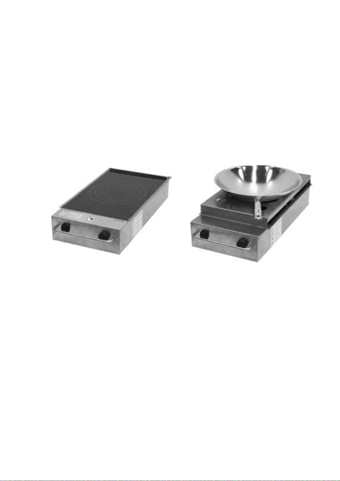
Fig.: varithek®induction hob 1/1-ik 3500 without
accessories and induction hob 1/1-ik 3500
with wok stand and wok
varithek®- The product innovation from Eisfink and Rieber
Page 2
induction hob
The conformity of the induction hobs 1/1-ik 3500, 1/1-ik 5000, 400-ik 3500 and 400-ik 5000 in
accordance with the directive 73/23/EWG, low voltage, is given. The manufacturer has the respective
documents.
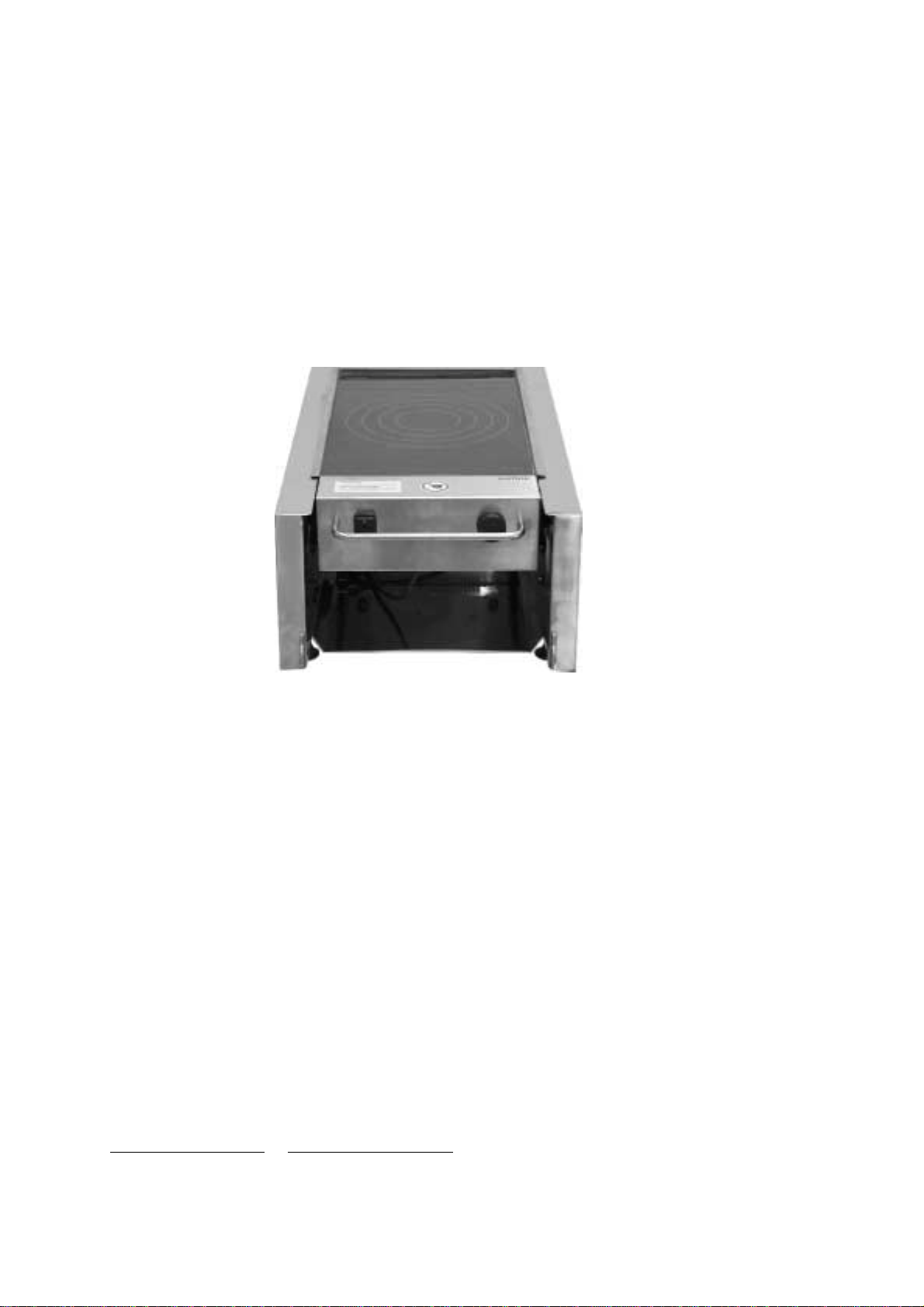
varithekinduction hob 1/1-ik 3500 in
varithektable-top system module
AST 255
Subject to technical changes !
Figures´and technical data may change slightly due to continuous further developments.
Manufacturer’s address
EISFINK MAX MAIER GMBH & CO.KG
Im Werkzentrum Weststadt
Rheinlandstr. 11
D 71636 Ludwigsburg
Fon: +49/7141/479-0
Fax: +49/7141/479-299
http://www.eisfink.de or http://www.varithek.de
As per: 08/04/2005

Page 3
induction hob
Table of contents
1 General 4
1.1 Introduction 4
1.2 Symbols for operating information 4
1.3 Laws, standards and directives 4
1.4 Delivery scope 5
1.5 Information for the operator 5
1.6 Warranty 5
2 Safety 6
2.1 Proper use 6
2.2 Improper use 6
3 Product description 7
3.1 Basic dimensions and technical data 7
3.2 Functional conditions 7
3.3 Equipment and parts in the standard delivery 7
3.4 Accessories and their use: varithek®system modules 8
4 Positioning / assembly 9
4.1 Mechanical 9
4.2 Electrical 9
5 Operation 10
5.1 General safety information 10
5.2 Commissioning and operation 10a
6 Cleaning and care 11
6.1 General 11
6.2 Initial cleaning, everyday cleaning and care 11
7 End of operation and operating breaks 12
8 Troubleshooting and possible causes 13
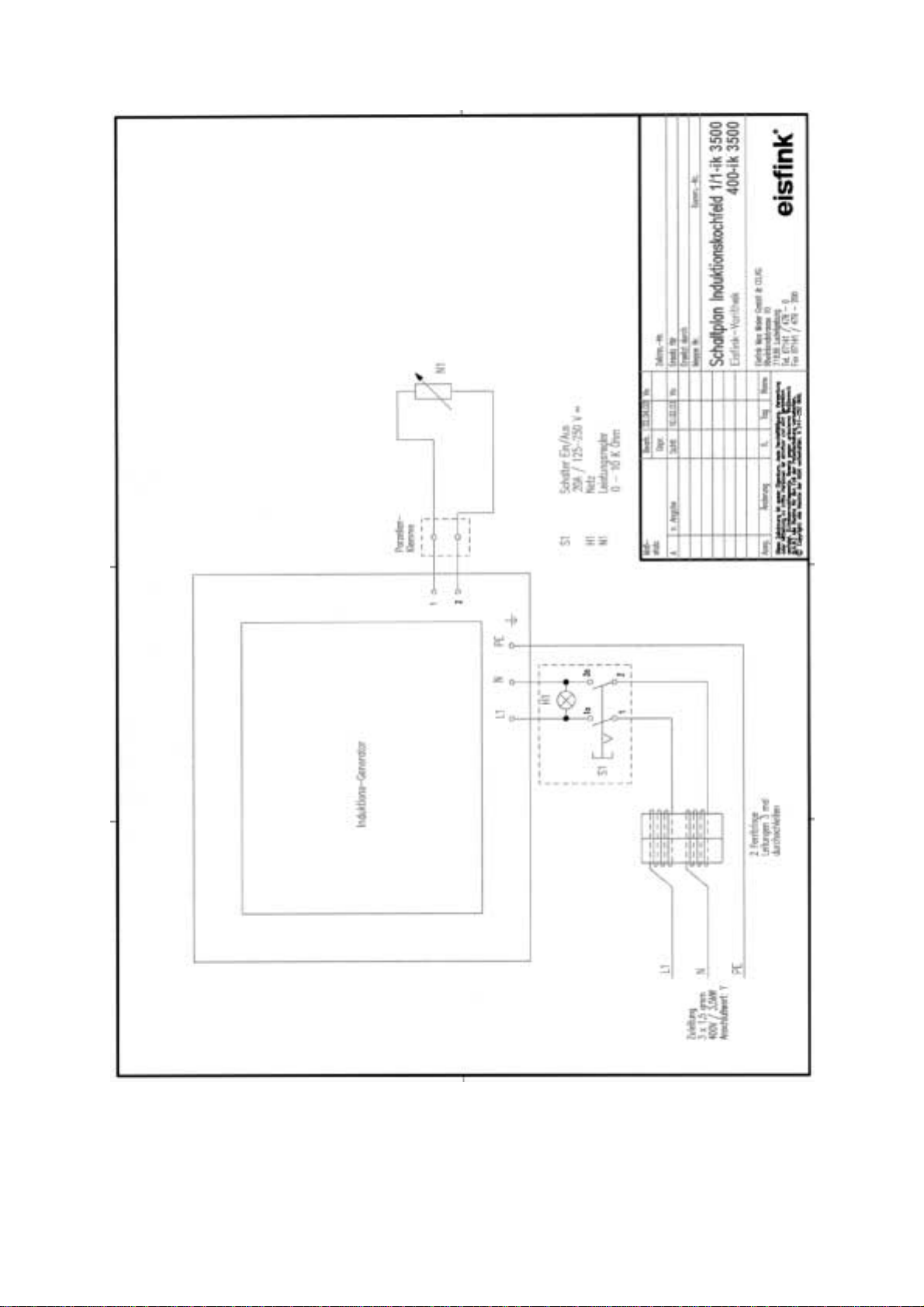
9 Circuit plan 1/1-ik 3500 and 400-ik 3500 14
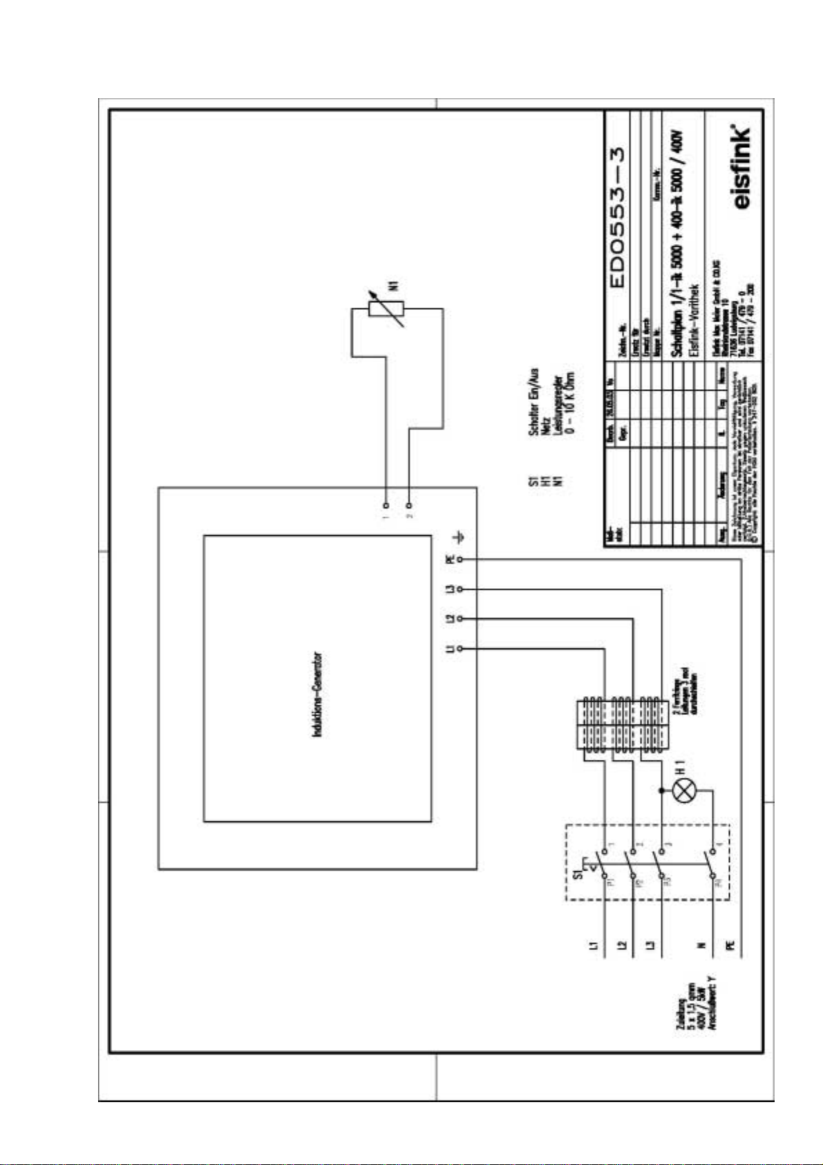
10 Circuit plan 1/1-ik 5000 and 400-ik 5000 15
Page 4
induction hob
1 General
1.1 Introduction
These operating instructions were specially compiled for the personnel operating the varithek®
induction hob. They contain important information about the assembly, operation and cleaning of the
system.
The operating instructions apply to all varithek®induction hobs.
Your induction hob version can be identified from the information on the type plate.
Read these operating instructions carefully before using the unit and ensure that all operators also
read these instructions before use. The operating instructions must always be available wherever the
unit is used. The operating instructions are part of the unit.
1.2 Symbols for operating information
Careful!
Indicates a potentially dangerous situation; non-observance could lead to slight or more serious injury
and/or damage.
Caution hot surfaces!
Indicates a potentially dangerous situation caused by hot surfaces; non-observance could lead to
burns and/or material damage.
Information!
Indicates operating advice for the best use of the appliance and other useful information.
1.3 Laws, standards and directives
The design and manufacture of this appliance conform with the requirements of the following guidelines and
regulations:
•Directive 93/43/EWG: Hygiene directive
•Directive 89/336/EWG: EMC
•Directive 73/23/EWG: Low-voltage directive
•EN 60335-1: Safety of household and similar electrical appliances
•EN 60335-2-36 EN 55011 EN 55014-2 EN 61000-3-2/-3-3

Page 5
induction hob
1.4 Delivery scope
•Please refer to the enclosed delivery papers for the scope of delivery and type of the individual parts.
•Remove the packaging from the parts and dispose the packaging material properly in an
environmentally friendly manner.
•Check the elements for any transportation damage. Record any damage on the haulage company’s
freight note and notify the supplier immediately.
1.5 Information for the operator
As the operator, you are responsible for:
•the proper and intended use of all parts of the varithek®induction hob,
•compliance with the safety provisions and safety information,
•training the operating personnel and ensuring their knowledge of the operating instructions,
•ensuring that the existing safety equipment functions properly,
•providing correct protective and work clothing and
•proper conditions for use.
1.6 Warranty
The current valid terms and conditions of sales and delivery of the company Rieber GmbH & Co. KG will
apply to all warranty claims. The terms and conditions of sales and delivery which are valid on the invoice
date shall apply.
Warranty claims made to the manufacturer must be based on the premise that the appliance has been used
properly (see the following chapter “Safety”).
Page 6
induction hob
2 Safety
2.1 Proper use
The varithek®induction hob is a professional cooking unit which allows a number of cooking processes to be
performed. This is only possible with pots and pans that are made of inductive material. The operating
instructions of the pot/pan manufacturers need to be observed for proper use of the pots and pans.
The following functions can be performed with the induction hob:
•Cooking, warming food up, keeping food warm,
•Frying and roasting.
Any other type of use is improper and could have unforeseeable consequences.
We recommend pot and pan material from Demeyère. We use pans from this manufacturer as
reference material which we test periodically.
2.2 Improper use
Improper use comprises all activities that are not listed in the cooking types above.
The following are particularly improper and dangerous:
•Heating objects other than food.
•Use of the induction hob to heat or humidify rooms.
Caution!
Never operate the unit unattended!
Warning! Danger of burns!
The Ceran®glass surface will become hot due to the radiation from the pots and pans.
The pots and pans heat up very quickly.
On a 5 KW unit at full power, oil will burn in max. 2 minutes.
Never pour oil / grease into pots and pans that are already hot. Danger of fire!
Never operate the unit with empty pots /pans
The safety and operating information stated in these operating instructions are not a substitute for
observance of legal and professional regulations (e.g. ZH1/37 –Safety rules for kitchens). These must be
observed in addition to the information provided in these instructions.
Caution!
People with pacemakers should consult their doctor as to whether they should stay close to an
induction hob.
Page 7
induction hob
3 Product description
The varithek®induction hob is a professional cooking unit designed as a table-top unit that can be used in
the varithek®table-top system modules AST 155 and AST 255 and the built-in system modules EST1 to
EST5. Inductive pots and pans with a diameter of 14 cm to 28 cm can be used on the induction hob.
The induction hob can be used as an induction wok when equipped with the varithek®wok stand and a
varithek®wok.
3.1 Basic dimensions and technical data
Dimensions / Model 1/1-ik 3500 1/1-ik 5000 400-ik 3500 400-ik 5000
Width 325 mm 325 mm 400 mm 400 mm
Depth 635 mm 635 mm 720 mm 720 mm
Height 140 mm 140 mm 140 mm 140 mm
Height with
wok stand 190 mm 190 mm 190 mm 190 mm
Connected load 1/N/PE 3/N/PE 1/N/PE 3/N/PE
AC 230 V 50 Hz AC 400 V 50 Hz AC 230 V 50 Hz AC 400 V 50 Hz
Connected output 3.5 kW 5.0 kW 3.5 kW 5.0 kW
Fuse 16 A 3x16 A 16 A 3x16 A
Electrical connection Earthed socket CEE plug Earthed socket CEE plug
IP protection class IP X4 IP X4 IP X4 IP X4
Weight: 9 kg 9 kg 9 kg 9 kg
3.2 Functional conditions
Tolerance, power supply Nominal voltage +6/-10%
Frequency 50 Hz
Diameter of pots/pans 140 mm (min.) to 280 mm (max.)
Wok diameter 380 mm
Ambient temperature +5°C to + 40°C
Relative humidity 30% to 90% (max.)
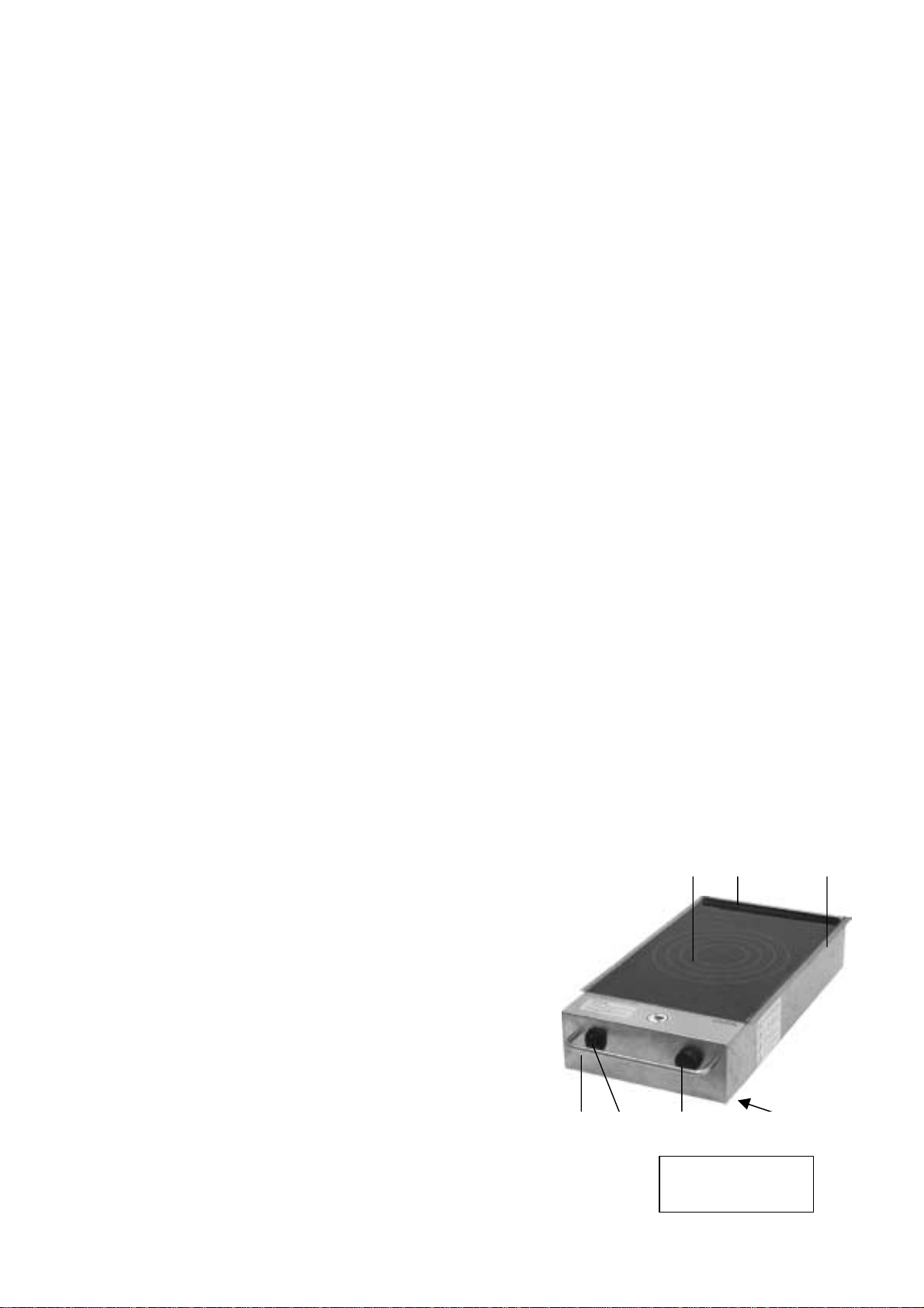
3.3 Equipment and parts in the standard delivery:
1: Carcass in stainless steel with integrated control casing
1.1: 4 rubber feet
1.2: Bracket for insertion in varithek®system module
1.3: Ceran®glass surface with markings on the induction
hob
1.4: Venting grille
1.5: Grease filter
1.6: Cleaning grille
1.7: Type plate
2: Carrying handle
3: Main switch with control lamp (1/1-ik 3500)
or rotary knob (1/1-ik 5000)
4: Output control (stepless)
5: Power cable with earthed plug (1/1-ik 3500)
or CEE plug (1/1-ik 5000)
1.3 1.4 1.2
Underneath not
shown
2 3 4 5

Page 8
induction hob
Information: ‘Cooking side’
3.4 Accessories and their use
1: varithek®wok WA
Use: The wok stand is placed on the carcass. Its opening must be placed exactly over the
markings on the Ceran®glass plate. It is the right way round if the information is on
the cooking side.
2: varithek®wok, stainless steel
Use: The wok is placed in the circular space of the wok stand which holds it in position.
The cut-out is designed so that there is a clearance of 1.5 mm between the lowest
point of the outer base of the wok and Ceran®glass plate.
3: varithek®table-top system module
AST 155 / AST 255
Use: The table-top system module is available in 2 different heights. It serves to hold
different varithek®function elements. It has moulded shelf rails on the left and right
inside walls which are used to hold the respective function element at the selected
height. The surface upon which the system module is placed must be horizontal.
When using varithek®function elements in the system modules, ensure that the
electrical power cables of the function elements are not caught and do not come into
contact with hot parts of the casing.
Correct positioning of the
induction hob without wok
on the upper shelf of the
system module
Correct positioning of the
induction hob without wok
stand in the second rail of the
side wall
4: varithek®built-in system module
EST 1 - 5
Use: As described in 3, however the built-in system module is usually permanently fitted
into an appropriate kitchen unit. The electrical power cables of the varithek®function
elements must either be reduced to the right length ex-works or shortened by a
specialist company as the built-in system module is equipped with 230 V earthed
sockets. 400 V units (induction hob 1/1-ik 5000) must be connected to a separate
400 V CEE socket with a 16 A fuse.

Page 8a
induction hob
Careful! Possible material damage!
Only the upper part of the front section of the system module may be opened.
The lower part of the front section must always remain closed so that the unit cannot slip out.

Page 9
induction hob
4 Positioning / assembly
When positioning and installing the unit, observe the electro-technical regulations, the fire safety and local
building regulations. There should be no flammable parts and objects close by. To ensure that the unit
functions properly and its operational safety, the unit must be installed, operated and serviced in accordance
with these operating instructions.
Careful! Possible material damage!
If the induction hob is moved to another location, the electrical connections should first be
disconnected and the accessories removed and transported separately.
4.1 Mechanical
Move the induction hob to its intended location. This must be even and clean.
The induction hob may not be placed on a flammable surface, next to flammable walls or on a hot surface.
When operating the induction hob close to a wall, partitions, kitchen furniture, decorative panelling etc. it is
recommended that these are made of non-flammable material, otherwise they must be cladded in a suitable
fire-proof heat-insulation material. The work surface must be able to bear a weight of at least 40 kg.
Careful! Possible material damage!
The openings for the ventilation and aeration should not be blocked or covered. Danger of
overheating!
2 Electrical
Before commissioning, check the power supply voltage and the type of power. In particular, check that these
comply with the information on the type plate. The type plate is located on the base of the control casing.
Observe the regulations of DIN / VDE 0100 ff. and the technical connection conditions (TAB) of the power
supply company (EVU).
The induction hob is equipped with a power cable with a 230 V earthed plug (1/1-ik 3500, 400-ik 3500)
and/or with a 400 V CEE plug (1/1-ik 5000, 400-ik 5000) for connection to a socket on site. Ensure that the
on-site socket has a fuse (16 A). The socket must be freely accessible so that the unit can be disconnected
from the power supply at all times. As a unit of the protection class 1, it must always be connected to the
protective conductor.
Careful! Possible material damage!
The power cable must be positioned so that it cannot become caught or overheated.
If in doubt, consult an electrician.
If the unit’s power cable is damaged, this must be replaced by the manufacturer, its customer service
or an electrician to avoid danger. Neutral conductor breaks may damage the unit.

Page 10
induction hob
5 Operation
5.1 General safety information
Careful! Possible material damage! Danger of injury! Danger of fire!
•Induction cooking units may only be operated with inductive pot and pan material.
Non-inductive pots will be recognised by the induction generator as unsuitable and
no energy will be radiated. Pots and pans that are made of semi-inductive material
will impair the cooking performance. The level of efficiency is significantly reduced;
the inductive generator may turn off automatically.
The induction generator can become damaged if unsuitable pots and pans
are used; in this case all warranty rights will be forfeited.
•The induction cooking units may never be operated unattended.
•Do not touch the Ceran®glass plate during operation. This becomes hot from the
heat radiated by pans used.
•The unit must be switched off and disconnected from the power supply if it is not
used for a longer period of time.
•Do not place any flammable substances (paper, card, material etc.) between the
cooking zone and the pots / pans as they may ignite.
•Do not place any metallic objects such as cutlery, tins, jewellery etc. on the cooking
area within the cooking zone. These will become hot very quickly.
•Do not keep any parts that are sensitive to magnetic energy (credit cards,
telephone cards, cassettes, watches etc.) close to the induction cooking units.
•The unit must be switched off immediately if there is any damage to the glass plate,
in particular tears.
•Aluminium foil or plastic vessels may not be placed on the glass ceramic surface.
•Please be aware that metal objects that the user wears, e.g. watches, rings and
other similar objects, may become hot if close to the surface of the cooking area.
•Any repairs may only be performed by qualified persons or persons recommended
by the manufacturer.
•Never operate the unit with empty pots/pans.
•The unit may not be transported during operation or as long as hot pots/pan are on
top.

Page 10a
induction hob
5.2 Commissioning and operation
The function of the induction hob was checked after production. Before commissioning for the first time,
please ensure that there is no packaging material or any other objects inside ventilation grille, cleaning grille
and the filters and that the unit is positioned correctly.
The induction hob is switched on by pressing the main switch or the rotary knob (0/1) and switched off again
by resetting the switch/knob. If the induction hob is switched on, the control lamp will shine (green).
Place the inductive pan in the centre of the induction hob (see markings on the hob) so that the base of the
pot/pan is heated evenly.
By turning the stepless output control to the right, energy is supplied immediately. Set the output control to
the required level.
If the pot / pan is removed from the hob, the induction generator will automatically regulate down.
Warning! Danger of fire! Danger of burns!
Never heat a pot or pan which is empty.

Page 11
induction hob
6 Cleaning and care
6.1 General
Careful! Danger of injury!
Allow the induction hob and the used pots / pans to completely cool down before starting to clean
them.
Careful! Possible material damage!
Do not use acidic cleaning agents. Cleaning agents may not contain any hydrochloric or
hydrofluoric acid because these can cause discoloration on the surfaces or even rust. Do not use
sharp-edged cleaning objects.
Careful!
Never clean with a water jet!
Cleaning agents
The casing parts of the unit should only be cleaned with the defined cleaning agents and a little
water. The cleaning agent is used in accordance with the manufacturer’s specifications. Heavy
soiling can be removed by first cleaning with e.g. a soft plastic fleece and then rinsing with clean
water. Then remove any cleaning agent residues with a damp cloth.
6.2 Initial cleaning, everyday cleaning and care
Before commissioning for the first time, clean the unit thoroughly to remove all packaging and soiling caused
by transportation.
Careful! Possible material damage!
Before cleaning the units, disconnect all electrical connections. Protect those parts (plastic parts)
that could react sensitively to the cleaning agent.
To clean the casing parts use a soft cloth and soaked in water containing a mild, grease-releasing, non-
abrasive cleaning agent. Grease and greasy pigment dirt can be removed easily using a general cleaning
agent, neutral cleaning agents or alkaline cleaning agents.
Solvent cleaning agents and non-abrasive emulsions are effective for removing heavy greasy soiling
(hardened oils and grease) on parts of the casing.
The casing parts, the connecting parts of the elements and the lower edges and reverse joints need to be
cleaned very carefully as this is where bits of food and dirt can collect.

Page 12
induction hob
Careful! Danger of injury
When cleaning the induction hob, take care of sharp edges. For this reason, always wear gloves
that are suitable for cleaning.
To clean the Ceran®glass, use a special Ceran®glass cleaner with a soft cloth or possibly a Ceran®glass
scraper to remove heavier soiling.
To completely remove all cleaning agent residues, clean with a damp soft cloth and water (not water jets)
until no more residues can be seen.
Careful! Possible material damage!
Do not use sharp-edged objects to clean the Ceran®glass as the Ceran®glass may become
scratched.
The induction hob must be cleaned after each use otherwise dirt will burn the next time it is used. Sugar and
food and residues containing sugar need to be removed from the Ceran®glass plate as soon as possible.
Please ensure that the induction unit is equipped with a grease filter in the base. The air cooling system and
the service life of the unit will be impaired by a heavily soiled grease filter.
Careful! Possible material damage!
Please ensure that the grease filter is cleaned in the dishwasher once a week!
Before inserting the grease filter, ensure that it does not contain any residual water.
7 End of operation and operating breaks
Switch the unit off after every use or before operational breaks by turning the output control to the left to
position “1”and the ON/OFF switch to “OFF”. The green control light will extinguish.
Careful! Danger of burns!
The used pots / pans store heat even after the unit has been switched off so that there is still a
danger of burns.
Careful! Danger of crushing!
Secure the induction hob against slipping.
Careful! Keep children out of danger zone!
Ensure that no children are allowed near the induction hob or play with the unit.

Page 13
induction hob
8 Troubleshooting and possible causes
In case of case of a malfunction, switch the induction hob off with the main switch or rotary knob (1/1-ik 5000,
400-ik 5000) and disconnect from the power supply.
Repairs to the induction hob may only be performed by a specialist company authorised by the manufacturer.
Careful!
Any work inside the casing or unit technology that is not performed by qualified personnel
authorised by the manufacturer will automatically lead to a forfeit of all warranty rights.
In case of any malfunctions that are not caused by dirt or inadequate cleaning, we recommend contacting
the supplier who will then name an authorised specialist company.
Warning!
Only original spare parts of the respective manufacturer may be used for repairs.
If the connecting cable of the induction hob has been damaged, the unit may no longer be used and
must remain disconnected from the power supply until the power cable has been replaced with an
original spare part by the manufacturer or an authorised specialist company.
Malfunction Possible cause Rectified by / with
Does not heat up
ON/OFF switch remains dark No power supply Check the fuse
Check plug connection
Defective cable Customer service should rectify
Does not heat up
ON/OFF switch shines green No inductive pan material Use the pan material recommended
by the manufacturer
Unit has been overheated Output will automatically reduce to 0
Switch off unit and allow to cool
Diameter of pan is less than
140 mm Use larger pan
Insufficient heating output Ventilation and aeration slits are
covered Uncover ventilation and aeration slits
Ventilator defective or dirty Customer service should rectify
Cleaning grille dirty Clean the cleaning grille in the
dishwasher and allow to dry

Vertretungen Inland (Domestic agents)
Baden-Württemberg Nord
Hans-Joachim Merkle
Hoffmannstraße 44
D-72770 Reutlingen
Tel. (0 71 21) 518-0
Fax (0 71 21) 518-302
Mobil (0172) 717 31 37
hans.merkle@rieber.de
Baden-Württemberg Süd
Martin Müller
Hoffmannstraße 44
D-72770 Reutlingen
Tel. (0 71 21) 518-0
Fax (0 71 21) 518-302
Mobil (0172) 939 98 42
martin.mueller@rieber.de
Berlin
Rieber Vertriebszentrum Nord
Am Bohldamm 5
D-14959 Trebbin
Tel. (03 37 31) 8 59-0
Fax (03 37 31) 8 06 45
hartmut.gutt@rieber.de
Dresden
Rieber
Vertriebszentrum Süd
Kieler Straße 41a
D-01109 Dresden
Tel. (03 51) 88 54 70
Fax (03 51) 8 80 78 34
gerhard.jacob@rieber.de
Frankfurt
Rieber Verkaufsbüro Mitte
Limburger Straße 74
D-65555 Limburg - Offheim
Tel. (0 64 31) 77 87-0
Fax (0 64 31) 77 87-29
hans.bien@rieber.de
Hamburg
Rieber Verkaufsbüro Nord
Meckelfelder Weg 2
D-21079 Hamburg
Tel. (040) 55 49 21-0
Fax (040) 55 49 21-90
sacha.lindenberg@rieber.de
Hannover
(Home Office)
Wolfgang Hirsch
Hannoversche Straße 34
D-30916 Isernhagen
Tel. (05 11) 61 00 30
Fax (05 11) 61 09 31
Mobil (0172) 717 33 97
wolfgang.hirsch@rieber.de
Köln
Rieber Vertriebszentrum West
Siemensstraße 1-5
D-50259 Pulheim
Tel. (0 22 38) 30 24-0
Fax (0 22 38) 30 24-24
werner.juhnke@rieber.de
Lotte (Home Office)
Andreas aus dem Moore
An der Dorfkirche 39
D-49504 Lotte
Tel. (0 54 04) 99 79 79-1
Fax (0 54 04) 99 79 79-2
Mobil (0172) 939 98 32
andreas.aus-dem-moore
@rieber.de
München
Rieber Verkaufsbüro Süd
Grabmeirstraße 1a
D-85276 Pfaffenhofen
Postfach 1331
D-85263 Pfaffenhofen
Tel. (0 84 41) 2775-0
Fax (0 84 41) 2775-27
uwe.kleinbeck@rieber.de
Tochtergesellschaften (Subsidiaries)
Österreich
Austria
Rieber + Grohmann GesmbH
Seybelgasse 13
A-1230 Wien
Tel. + 43 [0] 1/ 8 65 15 10
Fax + 43 [0] 1/ 8 65 15 10-10
www.rieber.at
office@rieber.at
Schweiz
Switzerland
Rieber ag
Handelszentrum Schöntal
Rorschacher Straße
Postfach 118
CH-9402 Mörschwil
Tel. + 41 [0] 71/ 868 93 93
Fax+ 41 [0] 71/ 866 27 37
www.rieber.ch
mail@rieber.ch
Holland
Netherlands
Rieber Benelux B. V.
Kamerlingh Onnesweg 2
NL-2952 BK Alblasserdam
Tel. + 31 [0] 78/ 6 91 83 05
Fax + 31 [0] 78/ 6 93 14 39
www.rieber.de
jerry.hol@nl.rieber.de
Frankreich
France
Rieber S.à.r.l.
8, rue du Périgord
B. P. 37
F-68272 Wittenheim Cedex
Tel. + 33 [0] 3 89/ 62 50 60
Fax+ 33 [0] 3 89/ 57 17 94
www.rieber.de
daniel.rewell@fr.rieber.de
Großbritannien
Great Britain
BGL-Rieber Ltd.
Unit 6 Lancaster Park
Industrial Estate, Bowerhill,
Melksham
GB-Wiltshire SN12 6TT
Tel. + 44 [0] 1225/ 70 44 70
Fax + 44 [0] 1225/ 70 59 27
www.bglrieber.co.uk
sales@bglrieber.co.uk
Tschechien
Czech Republic
Rieber spol. s.r.o.
Pod Zvahovem 25 A/1059
CZ-152 00 Praha 5
Tel. + 420 [0] 2/ 51 68 05 89
Fax+ 420 [0] 2/ 51 68 06 31
www.rieberCZ.cz
rieber@rieberCZ.cz
Polen
Poland
Gastromedia Sp.z.o.o.
ul. Sobocka 19
PL-01-684 Warszawa
Tel. + 48 [0] 22/ 8 33 87 07
Fax + 48 [0] 22/ 8 33 87 22
www.gastromedia.pl
gastro@gastromedia.pl
Vertretungen (Agencies)
Italien
Italy
Rational Distribution S.r.l.
Via Giotto 6 B
Zona Commerciale Sud
I-39100 Bolzano
Tel. + 39 [0] 471/ 93 13 31
Fax + 39 [0] 471/ 93 15 91
www.rational.it
staff@rational.it
Spanien
Spain
Oms y Vinas S.R.C.
Carrer Pere IV, 459
E-08020 Barcelona
Tel. + 34 [0] 93/ 2 78 09 60
Fax + 34 [0] 93/ 2 78 12 02
www.oyv.es
oyv@oyv.es
Adresse (address)
Rieber GmbH & Co. KG
Hoffmannstraße 44
D –72770 Reutlingen
Tel. +49 [0] 7121 / 518 - 0
Fax +49 [0] 7121 / 518 - 302
E-Mail: info@rieber.de
www.rieber.de
Stempel des Fachhändlers
(Dealer stamp)
ZNW 11930924,000,00,1 09/2005
Nr.:36642607/
This manual suits for next models
3
Table of contents
Other Rieber Commercial Food Equipment manuals


Popular Commercial Food Equipment manuals by other brands


Giorik
Giorik Stoddart 700 Series Installation, operation & maintenance manual

Henny Penny
Henny Penny FlexFusion Platinum installation manual

Frigomat
Frigomat AGG.2014 Series Use and maintenance manual

Atlas Metal
Atlas Metal WQHC Series Service and installation manual

FM
FM STF 610 user manual

Royal Catering
Royal Catering RCCC-238-W user manual


