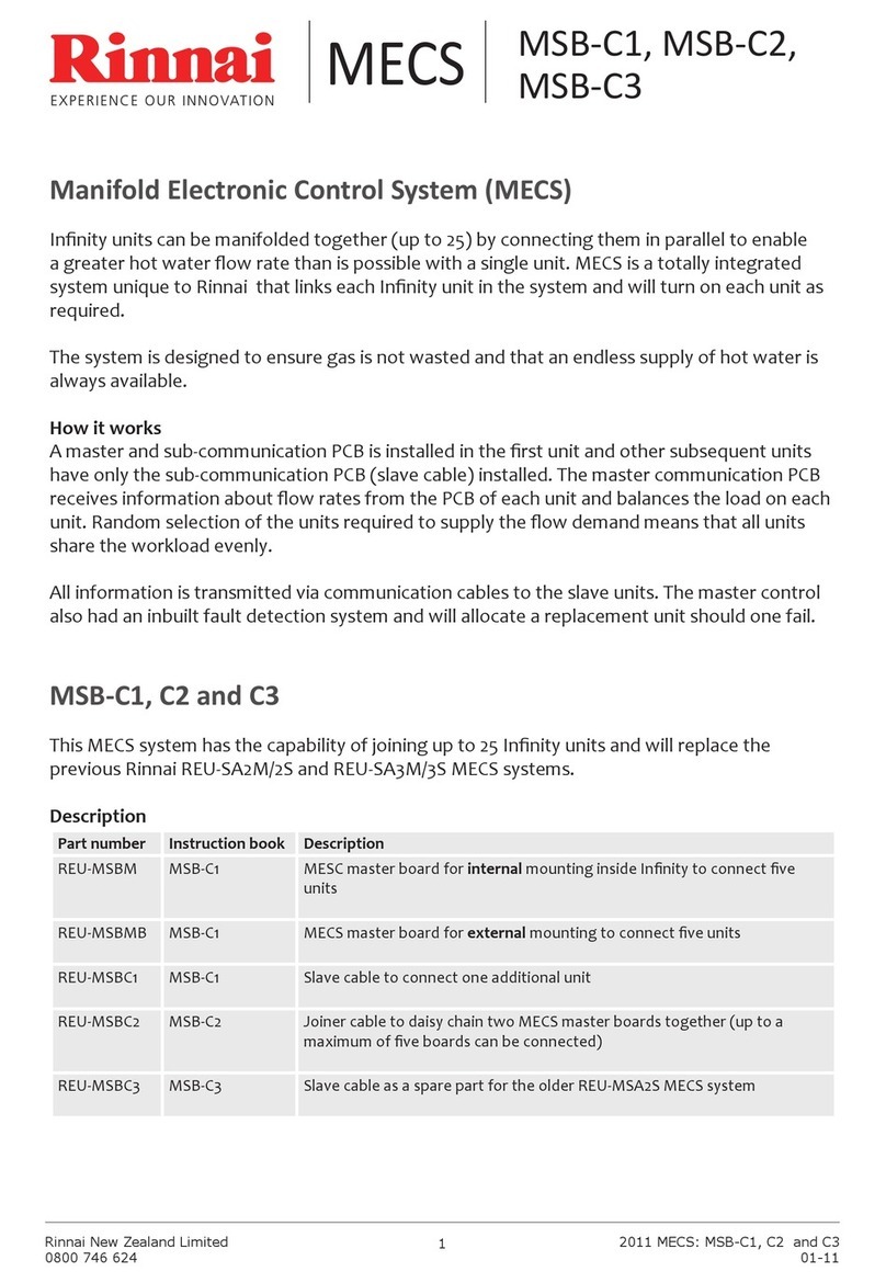
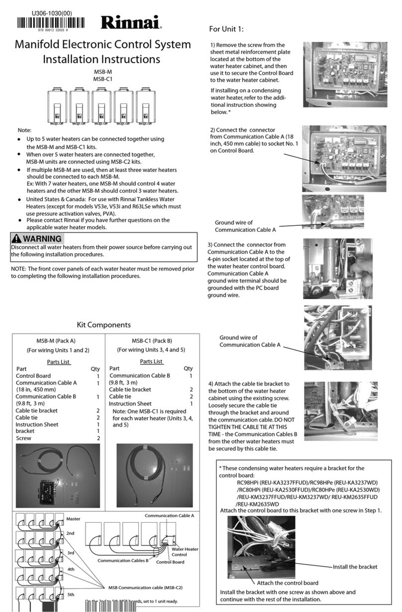
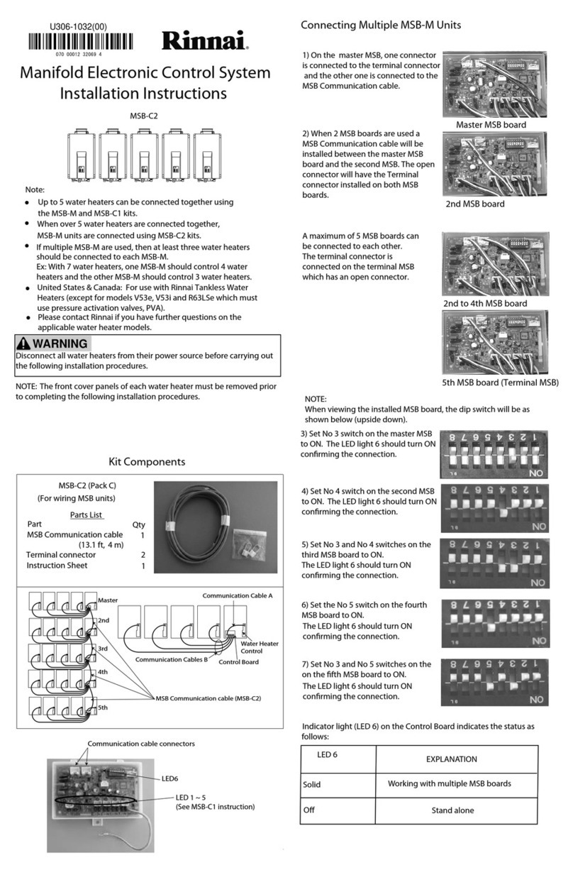
Rinnai brivis ZonePlus User manual

ZonePlus
Owner’s Manual
NOTE TO INSTALLER: THIS MANUAL SHOULD BE LEFT WITH THE HOME OWNER.

i
Introduction
Congratulations on purchasing a ZonePlus Climate Control System.
ZonePlus brings the possibility of total indoor climate control. It allows
you to optimize the performance of your Ducted Gas Heater or Dual
Comfort System throughcustomized comfort control.
Your specialist Rinnai Dealer has divided your home into zones that can
be operated and controlled separately. The exact configuration of your
ZonePlus system will determine the programming features that are
enabled, as well as the number of zones that can be heated (or cooled)
simultaneously. ZonePlus may be operated manually, or you can
program your comfort schedule and let the system automatically do the
rest.
Please take the time to review this guide and enjoy the benefits of your
ZonePlus ClimateControl System.
Specifications subject to change without notice.
© Rinnai Australia Pty Ltd 2018
Application
ZonePlus may be used on the following Ducted Systems:
•StarPro Ducted Gas Heaters produced after 20 May 2013 (serial
number greater than 995000)
•Dual Comfort Systems StarPro Heaters and ICE Refrigerated
Cooling)
•StarPro Ducted Gas Heaters and Evaporative Cooling
•Zoning is not available duringEvaporative Cooling mode
•The NC-6 Master Controller, or any other ZonePlus NC-6, where
fitted, will operate a Evaporative cooler with all normal features and
functionality
Note: ZonePlus systems should only be installed by
authorised Rinnai Dealers who have successfully completed
the ZonePlus Training Module.
Note: Your Rinnai Dealer has specified your ZonePlus System
Configuration Summary in Table 2.

ii
Table of Contents
INTRODUCTION....................................................................... i
APPLICATION..........................................................................i
1.0 ZONEPLUS – AT A GLANCE..............................................1
1.1 ZonePlus Sensors / Components ....................................... 2
1.2 ZonePlus System Configuration - Summary....................... 5
1.3 The Comfort Schedule........................................................6
2.0 MULTI TEMPERATURE SET POINT SYSTEMS (MTSP)... 8
2.1 MTSP Quick Start Guide..................................................... 8
2.2 Setting the Time & Day....................................................... 9
2.3 User Settings......................................................................9
2.4 Zone Identification ..............................................................10
2.5 Manual Operation ...............................................................11
2.6 Automatic Operation........................................................... 12
2.6.1 Programming Your Comfort Schedule ............................. 12
2.6.2 Operating in “Auto” ..........................................................14
2.6.3 Temporarily Overriding “Auto”.......................................... 14
2.6.4 Advancing the Current “Auto Program” Period................. 15
3.0 SINGLE TEMPERATURE SET POINT SYSTEMS (STSP) . 16
3.1 STSP Quick Start Guide..................................................... 16
3.2 Setting the Time & Day....................................................... 18
3.3 User Settings...................................................................18
3.4 Zone Identification...........................................................18
3.5 Manual Operation............................................................18
3.6 Automatic Operation........................................................19
3.6.1 Programming Your Comfort Schedule..........................20
3.6.2 Operating in “Auto Program” ........................................21
3.6.3 Temporarily Overriding “Auto” ......................................21
3.6.4 Advancing the Current Program Period........................21
4.0 OPERATING THE FAN ONLY - MTSP & STSP...............22
5.0 NETWORKER - SECURITY ............................................22
5.1 Setting the PIN................................................................22
5.2 Locking the Networker.....................................................23
5.3 Unlocking the Networker .................................................23
6.0 ERROR MESSAGES ......................................................23
6.1 Fault Message Retrieval..................................................24
6.2 System Reset..................................................................24
7.0 TROUBLESHOOTING ....................................................24
Appendix...............................................................................26
Terms of Warranty.................................................................31

1
1.0 ZONEPLUS – AT A GLANCE
Zone
One room or a group of rooms, normally selected on the basis of usage
or that have similar heating or cooling needs.
Controlled Zone
A zone that is separately controlled by its own zone sensor and zone
damper. There are as many zone sensors in the home comfort system
as there are ControlledZones.
Common Zone
A zone that is not separately controlled by its own sensor and
zone damper. It operates whenever heating or air conditioning
is on.
Constant Zone
A predetermined zone, typically the largest and containing the return air,
is designated the Constant Zone and functions as a Common Zone
only during refrigerated cooling mode to ensure the minimum cooling
airflow requirements are met.
Multi Temperature Set Point (MTSP) ZonePlus System
The zone temperature set point can be set independently across all
Networkers and/orTemperature Sensors.
Single Temperature Set Point (STSP) ZonePlus System
The zone temperature set point is the same across all Networkers and/or
TemperatureSensors.
NC-6 Networker Controller
Primary user interface with LCD display. Where multiple NC-6s are
installed, the “Master” Networker Controller can be identified by the
word “Clock” displayed adjacent to Key “5” when system is OFF.
NT-1 Remote Temperature Sensor
Zone temperature sensor with LED that blinks during communication
with Master NC-6. Additional NC-6 Networkers can be used in place of
up to 3x NT-1 sensors.
Sensor
Both the NC-6 and NT-1 function as zone (room) temperature sensors
–in this context, the word “sensor” in this manual can apply to both.
System Configuration
Details of your system configuration and capabilities are summarized
in Table 2: ZonePlus System Configuration Summary.
Comfort Schedule
The NC-6 Networker Controller of your ZonePlus System enables
you to program up to five time periods and temperature settings per
day, for each controlled zone, for both Heating and Refrigerated
Cooling modes.
This manual separately details operation and functionality for:
- Multi Temperature Set Point (MTSP) systems (p.8)
- Single Temperature Set Point (STSP) systems (p.17)

2
1.1 ZonePlus Sensors / Components
Diagram 1. NC-6 Networker Controller
Diagram 2. NT-1 Remote Temperature Sensor
Note: These components do not require batteries.

3
Table 1:Networker NC-6 Functions
The On/Off Button
This is the button to turn the Networker ON or OFF
The Function Key
The Function Key, when used in conjunction with Keys “1” & “2”, allows the user to perform specialised functions such as
message repeating and Networker locking
The Mode Key
If both Heating and Cooling systems are connected to the Networker, this Key allows you to switch between them.
When an appliance is selected, the mode will appear at the bottom of the screen e.g. “Heating” or “Cooling”
Heartbeat
A flashing heart icon in the bottom right hand corner indicates that the room temperature is being sensed from this Networker
Program Key
This control Key is used to set the Networker's automatic program
Auto Key
The auto function allows the user toswitch betweenthe Auto Program andthe Manual Operation.
The Rotary Dial
This Dial is used to change the settings and parameters
Variable Keys
The Keys numbered“1” -“5” vary their function depending onthe program or mode displayed. They will only have a function if text
appears on the screen besidethe Key and in some cases ablack rectangular box. Keys used for zone function may also displayan Arrow.

4
Table 1:Networker NC-6 Functions (Cont’d)
The NC-6 LCD Display Screen
•Displays information about the system. The screen shows the current time via a Digital Clock in the top left corner, the Day of the Week on the left-hand
side, and the type of applianceselectedat thebottom
•The display will also show scrolling messages across the top of the screen, which can display some of the appliance’s operational states
Flame Symbol
The flame symbol will appear on the display when the heater is switched on. This symbol will flash during cool down
at the end of the heating cycle
Fan Symbol
The fan symbol will appear on the display when the heater is switched on. This symbol will flash during cool down at theendof theheating
cycle.
Thermometer
The thermometer on the display registers the current room temperature. Beside it is a small marker which indicates the
temperature that the heater is currently set to maintain
Padlock Symbol
When the child-proof lock has been set, a padlock will appear on the screen. For more information, refer to the section on
Locking the Networker.
Snowman Symbol –Dual Comfort systems only (Add-On Air Conditioning)
The snowman symbol indicates the refrigeration compressor is running. A flashing snowman indicates the compressor is in a
safeguard time off period

5
1.2 ZonePlus System Configuration -
Summary
Below is a summary of your system’s configuration. A detailed
version of this table (located in the Appendix) should also be
completed by your installer and retained for future reference.
Table 2: System Configuration Summary
ZONE
SENSOR TYPE^^
(NC-6 / NT-1)
ZONE A
ZONE B
ZONE C
ZONE D
COMMON
(If applic) --
CONSTANT
(MTSP - If applic)
--
ZONE: A B C D NIL
(circle one only)
^^NC-6 Master Controller displays 'Clock' indicator when OFF.
^Zoning is not available during Evaporative Cooling mode.
Maximum no. of Zones for HEATING:
Max. no. of Zones for REFRIGERATED COOLING:
ROOM(S)
ZONEPLUS SYSTEM CONFIGURATION - TO BE COMPLETED BY INSTALLER
HEATING ONLY
DUAL COMFORT
HEATING & EVAPORATIVE COOLING^
MULTI TEMPERATURE SET POINT
SINGLE TEMPERATURE SET POINT
SYSTEM DESIGN CONDITIONS

6
1.3 The Comfort Schedule
NC-6 Networker Controllers and NT-1 Remote Temperature
Sensors are programmed from factory with a default “Comfort
Schedule”times and temperatures detailed in Table 3.
In MTSP systems the “Comfort Schedule”settings for each
zone sensor is unique, i.e. four zones require four Comfort
Schedules. This provides you with ultimate flexibility, allowing you
to vary your Periods, Times and Temperatures for each zone.
In STSP systems the “Comfort Schedule” operates within the
same Period, time and temperature setting for all zones; i.e. up to
four zones will require one Comfort Schedule, with zones
activated or deactivated as required.
Table 3. Default Comfort Schedule Times and Temperatures
Use the templates located in the Appendix to customize your
personal “Comfort Schedule”.
First you need to decide what time you want each of the Periods to
begin for the Day Block selected, i.e. the “Wake” Period for Monday
to Friday. For MTSP systems this time can vary for all zones while for
STSP systems there can only be one time for all zones.
Second, select the desired Heating temperatures for winter operation.
Then select the Time and Temperatures for each of the remaining
Periods and days as required.
You may also program your Refrigerated Cooling (if fitted) “Comfort
Schedule”.
•Refer to Table 3for the default Comfort Schedule
•Refer to Table 4for an example of a MTSP Comfort Schedule
•Refer to Table 5for an example of a STSP Comfort Schedule
Time Heat°Cool°Time Heat°Cool°Time Heat°Cool°Time Heat°Cool°Time Heat°Cool°
Mon - Fri 6.00 20 20 9.00 -- -- 4.00 20 20 9.30 20 20 10.00 -- --
Sat - Sun 6.00 20 20 9.00 -- -- 4.00 20 20 9.30 20 20 10.00 -- --
Wake
Leave
Return
Pre-Sleep (Optional)
Sleep

7
Table 4. MTSP Comfort Schedule Example (2zone system example is shown)
ZONE A
Living
Time Heat°Cool°Time Heat°Cool°Time Heat°Cool°Time Heat°Cool°Time Heat°Cool°
Mon - Fri 7.00 19 24 8.00 -- 28 5.00 21 24 10.30 -- --
Sat - Sun 8.00 20 24 8.00 21 24 6.00 21 24 11.00 -- --
ZONE B
Sleeping
Time Heat°Cool°Time Heat°Cool°Time Heat°Cool°Time Heat°Cool°Time Heat°Cool°
Mon - Fri 6.00 19 24 8.00 -- 28 6.00 21 24 8.30 -- --
Sat - Sun 8.00 20 24 9.00 18 24 6.00 21 24 9.00 -- --
Sleep
Wake
Leave
Return
Pre-Sleep
Sleep
Wake
Leave
Return
Pre-Sleep (Optional)
Table 5. STSP Comfort Schedule Example (2zone system example is shown)
Time Heat°Cool°Time Heat°Cool°Time Heat°Cool°Time Heat°Cool°Time Heat°Cool°
Mon - Fri 7.00 20 24 8.00 -- 28 5.00 21 24 11.00 -- --
Zone A ON ON OFF ON ON ON OFF OFF
Zone B ON ON OFF OFF OFF OFF OFF OFF
Time Heat°Cool°Time Heat°Cool°Time Heat°Cool°Time Heat°Cool°Time Heat°Cool°
Sat - Sun 6.00 20 24 9.00 20 24 6.00 21 24 11.00 -- --
Zone A ON ON ON ON ON ON OFF OFF
Zone B OFF OFF OFF OFF ON ON OFF OFF
Sleep
Wake
Leave
Return
Pre-Sleep (Optional)
Sleep
Wake
Leave
Return
Pre-Sleep (Optional)
Note: “- -” in the temperature location indicates the zone has
been set to “OFF”

8
2.0 MULTI TEMPERATURE SET POINT
SYSTEMS (MTSP)
A MTSP system provides you with ultimate conditioning
flexibility, allowing you to set the temperature of each zone
independently. MTSP does not apply to Evaporative Cooling
(if fitted).
2.1 MTSP Quick Start Guide
The following quick start procedure enables you to use your
ZonePlus before you learn all the details of the system’s operation.
Please ensure your dealer has provided you with details on zone
identification, the capabilities of your heating and cooling system, and
the maximum or minimum number of zones that can be operated
simultaneously for heating or cooling design conditions (see Table 2).
Quick Start Guide: Heating
1. Press the Mode Key “M” until “Heating” is displayed at the
bottom of the screen
2. Press Key “3” until “A” appears in the top right hand corner of
the screen, indicating Zone “A” access
3. Press the On/Off button to turn on and call for Heating
4. Increase the desired temperature set point to above the room
temperature by turning the rotary dial clockwise
5. Press Key “3” to gain access to Zone “B”
6. Increase the desired temperature set point to above the room
temperature by turning the rotary dial clockwise
7. Repeat steps 5 & 6 for Zone “C” and Zone “D” (if installed)
Quick Start Guide: Refrigerated Cooling
1. Press the Mode Key“M” until “Cooling” is displayed at the
bottom of the screen
2. Press Key “3” until “A” appears in the top right hand corner of
the screen, indicating Zone “A” access
3. Press the On/Off button to call for Cooling
4. Decrease the temperature set point to below room temperature by
turning the rotary dial anticlockwise
5. Press Key “3” to gain access to zone “B”.
6. Decrease the temperature set point to below room temperature by
turning the rotary dial
7. Repeat steps 5 & 6 for Zone “C” and Zone “D” (if installed)

9
2.2 Setting the Time & Day
This is to be done at the NC-6 Master Controller, identified by
the word “Clock” opposite Key “5” or the Clock Key.
Diagram 4:NC-6 Setting the Time & DayDisplay
1. Press the On/Off button to turn the system OFF
2. Press Key “5”, Clock Key, and the screen will display the
message "Clock setting mode", then the Digital Clock will flash
3. Use the Rotary Dial to set the correct time
4. To set the day, press Key “1”, the Day Key until the correct day of
the week appears on the left of the screen, e.g. "Tue"
5. Press Key “5” the Clock Key again to save your new settings
2.3 User Settings
Accessing the user settings allows you to customise certain
features on the NC-6 display and modify “Auto Program”
functions; these include:
•Clock displayed in either 12hr or 24hr time
•Temperature displayed in either °C or °F
•Day grouping (3 options) when in “AUTO” mode
•Enable or disable the “Pre Sleep” option
Diagram 5:NC-6 User Settings in Heating Operation Display
To access and change the user settings at the NC-6 Master
Controller:
1. Press Key “5” and release
2. Press and hold Key “4” until the following message begins
to scroll across the top of the screen. “User setting mode”
3. You now have access to the user settings. Please refer to
Table 6 for user setting options and change as required
4. Press the On/Off button to save and exit user setting
Note:If multiple NC-6 Networker Controllers are installed, only
the Master NC-6 Controller has the ability to set the Clock Ti
me
and Day. The Master NC-6 Controller
can be identified by the
word "Clock" beside Key “5”, when the ZonePlus system is
in
the OFF position.
Day Key
Clock Key

10
Table 6: User Setting Options
2.4 Zone Identification
Your Rinnai Dealer has divided your home into zones that can be
operated and controlled separately. The exact configuration of your
ZonePlus system will determine the programming features that are
enabled, as well as the number of zones that can be heated (or cooled)
simultaneously. You may operate your ZonePlus system in either
“Auto Program” or “Manual”.
Diagram 6:NC-6Heating Operation Display
Only the zones that have been installed and configured by the
installer will be displayed. For MTSP systems when the system is
OFF the available zones can be viewed by pressing Key “3”.
With a four zone system the NC-6 Controller will cycle through zones
“A”, “B”, “C”& “D”when Key “3” is pressed. The zone in view can
be identified in the top right hand corner of the screen.When the
system is ON the installed zones are displayed adjacent to Keys“4”
& “5”, as shown in Diagram 6.
The zone Arrow indicators:
•Solid indicates the associated zone is Heating (or Cooling) as the
zone set temperature has not been satisfied
•Flashing indicates the associated zone set temperature has been
satisfied
User Input
Option
Key “1”
Changes the day grouping to one of the
following:
- Individual days: Selected when each day
flashes individually and sequentially
- Week day and weekend Block:Selected
when Mon to Fri flash and then Sat-Sun flash
- All week days: Selected as one group
when Mon to Sun are all displayed at once
Key “2”
Enables and disables the “Pre Sleep” option
Key “3”
Displays the temperature in either °C or °F
Key “5”
Displays the time in either 12hr or 24hr format

11
2.5 Manual Operation
Operating your system in “Manual” will require you to turn zones ON
and OFF as desired and adjust zone temperature set points
independently.
Diagram 7:NC-6 Manual Operation Display
To operate yoursystem in “Manual”:
1. Use the On/ Off buttonto turn theNetworker OFF
2. If you have multiple appliances on the Network, press the Mode Key
“M” until the word “Heating” or “Cooling” appears (as required) at
the bottom of the screen. If you have the Networker ON while
switching between appliances you could start the wrong one
inadvertently
3. Turn the Networker ON and press the “AUTO” Key until “Manual”
appears in the bottom left-hand corner of the screen
4. The Zone(“A”in Diagram 7)Set Temperature (24°C in Diagram 7)
will now appear at the top of the screen. The current zone (Room)
temperature (22°C in Diagram 7) is still visible in the top right hand
corner ofthe screenbeside the associated zone “A”
5. This Set Temperature is the temperature the system is required to
maintainforthe nominatedzone
•To increase the Set Temperature rotate the dialclockwise
•To decreasethe Set Temperature rotate the dial anti-clockwise
6. To view and or adjust the set point of another zone in the system
press Key “3”. Review the associated zones temperature set point
and adjust if required by rotating the dial to the desired temperature –
the zone being accessed will flash in the top right hand corner of the
LCD display
7. To turn the zone OFF change the Set Temperature to “0°” ; the Set
Temperature will display“--“
8. Repeat the above stepsfor other zones as required
9. To turnthe entire system OFF, press the On/ Off button
The system will operate until all zone set temperatures are
satisfied, at which time it will shut off.
Once the temperature set point for a zone is satisfied the zone
description (i.e. “Zone A”) and an Arrow, both adjacent to Key “4” &
“5”, will flash. If the zone set point is not satisfied the zone description
andArrowwill remainsolid.
Note: The Networker remembers your last settings, and reverts
back to them the next time you select “Manual” operation.

12
2.6 Automatic Operation
The Networker allows you operate your system automatically in
accordance with a predetermined “Comfort Schedule” (also
known as the “Auto Program”).
The Networker has a pre-set (default) Comfort Schedule for
Heating and Cooling already stored in its memory. This “Auto
Program” covers the entire week and is based on the average
operating time of the unit with all temperatures for Heating and
Cooling set to 20°C.The “Auto Program” default settings are
detailed in Table 3.
Diagram 8:NC-6 Auto Program Display
2.6.1 Programming Your Comfort Schedule
You may alter the default “Auto Program”to suit your
requirements.
This will require you to enter the Period start time, desired Heating (and
Cooling) temperatures for each “Period”, “Day”Block and zone. For
an example of this please refer to Table 4. Take a few moments to
complete the MTSP Comfort Schedule template in the Appendix
prior to accessing the “Auto Program”.
Diagram 9:NC-6 Programming Comfort Schedule Display
Note: When accessing the Comfort Schedule of another zone,
the “Set Temperature” value (22° in Diagram 8) on the LCD
may temporarily display “??”.
Note: If at any time you wish to reset the entire Comfort Schedule
(Time & Temperature for all Periods) for the associated zone,
press Key “4”, the “Reset” Key.
Note: A MTSP ZonePlus system can operate zones in either
“Auto” or “Manual” simultaneously.
Period
Time/Temp
Current
Period
Day
Week
Block
Reset

13
Programming the Comfort Schedule:
1. Turn the Networker OFF and confirm you are in your desired Mode,
either Heating or Cooling. If not, press the Mode Key “M” until the
word “Heating” or“Cooling” appears in the bottom of the screen
2. Please note Heating and Cooling program changes must be
completed independently for each zone. Also when changing Mode
from “Heating” to “Cooling” and vice-versa, this must be conducted
prior toentering theprogrammingscreen
3. Press the “PROG” Key and you will notice the word “Auto
Program” appear at the bottom ofthe screen. The Digital Clock (e.g.
“10:28p”, Diagram 9)at the top of the screen will also begin to flash.
4. Select the Day Block (e.g. “Mon to Fri”)
Press Key “1” to select the Block you want to change settings to.
This selects either the Weekday Block or the Weekend Block. These
were previously set upin Section 1.3 User Settings
5. Select the Period (e.g.“Wake”)
Press Key“2” (Period) until the required Period is displayed.
6. Setting the Period Start Time
Press Key “3” until the time begins to flash. Rotate the dial to set the
desired Start Timefor theselected “Period” and “Day” Block
7. Setting thePeriod Temperature
Press Key “3” to change from time to temperature. Rotate the dial to
set the desired Temperature for the selected “Period”, “Day” Block
and“Time”
8. ChangePeriod
Press Key“2” (Period) until the next Period is displayed.
Repeat steps 6 and 7 until all Periods are complete for the selected
“Day”Block and zone
9. Change Day Block
If there is more that one Day Block (e.g. “Mon-Fri”& “Sat-Sun”)
Press Key“1” to select the next Block and repeat steps 5 to 8
10. ChangeZone
When programming of the first zone is complete (typically “A”) you
will need to now program the remaining zones. To enter another
zone for programming, please refer to the below steps:
•
Press Key “PROG” to exit the programming screen
•
Press Key “3” andcycle to the next zone (typically“B”)
•
Press Key “PROG” to enter the programming screen of the
next zone. Repeat steps 4 to 9
11. Save and Exit
Press the “PROG” Key to Save andExit
Note: To turn a zone OFF, change the set temperature to
“0°C”. The display will show “- -” in the “Set” temperature
location.

14
2.6.2 Operating in “Auto”
1. Determine the desired Mode, either Heating or Cooling, by pressing
the Mode Key marked “M” to select. The bottom of the screen will
read“Heating” or “Cooling” (if installed)
2. Select the zone you want to operate in “Auto” by pressing Key “3”
The zone can be identified inthe top right hand corner of the screen
3. Turn thesystem ON by pressing the On/Off button
4. Press the “AUTO” Key until “Auto Program” appears on the LCD
screen (if not already in“Auto Program”)
5. Cycle through all zones by pressing Key “3”and at each zone repeat
step 4 to set the zone into “Auto”
2.6.3 Temporarily Overriding “Auto”
If the “Auto Program”temperature settings do not suit your
immediate requirements, you may want to temporarily override
each zone.
This modification must be completed for each zone independently
and it is not a requirement to temporarily override all zones; i.e.
you may want to temporarily increase or decrease the
temperature of zone “B” only.
Diagram 10:NC-6 MTSP Temporary Override Display
To temporarily override “Auto Program”:
1. With the unit ON and in the “Auto Program” select the zone you
wish to modify the pre-set room temperature of by pressing Key “3”,
refer toDiagram 10,currentlyin Zone “C”
2. Use the Rotary Dial to increase or decrease the current temperature
setting
3. While in override, the word “Temporary” will flash at the bottom of
the screen until the current Period ends, or the “Cancel” Temporary
Override (Key “2”) is pressed to returnto the normal program; referto
Diagram 10
4. To temporarily change theset temperature of another zone press Key
“3” until the desired zone is displayed in the top right hand corner of
the screenand repeat step 2
Note: A MTSP ZonePlus system can operate separate zones in
either “Auto”or “Manual” simultaneously.
Note: The Networker will revert to “Auto Program” at the
next scheduled Time Period.

15
2.6.4 Advancing the Current “Auto Program”
Period
You may wish to skip to the next Period, e.g. advance from
“Wake”to “Leave”.
1. With the unit ON and in “Auto Program”, press Key “2” to advance
the Period
2. Key “2”, normally the “Adv Period” Key,has now become the
“Cancel Adv Period” Key. Press this Key to return to the normal
program
3. To advance the Period of another zone, press Key “3” until the
desired zone is displayed in the top right hand corner of the LCD
screen and repeatstep 1
Note: The Networker will revert to “Auto Program” after the
current period ends.

16
3.0 SINGLE TEMPERATURE SET POINT
SYSTEMS (STSP)
A STSP system provides you with the capability of setting one
temperature for Heating and another temperature for Cooling.
The zone temperature set point is the same across all
Networkers and/or Temperature Sensors.
3.1 STSP Quick Start Guide
The following quick start procedure enables you to use your
ZonePlus before you learn all the details of the system’s operation.
Please ensure your dealer has provided you with details on enabling
zones, the capabilities of your Heating and Cooling system, and the
maximum or minimum number of zones that can be operated
simultaneously for Heating or Cooling design conditions (see Table 2).
Quick Start Guide: Heating
1. Press the Mode Key “M” until “Heating” is displayed at the
bottom of the screen
2. Press the On/Off button to turn the system on
3. Increase the desired temperature set point to above the room
temperature by turning the rotary dial clockwise
4. Press Key“4” to enable and disable zones “A” & “B” for heating.
An Arrow will appear adjacent to Key “4” on the screen to inform
you that the zone is enabled
5. Press Key “5” to enable and disable zones “C” & “D” (if
installed) for heating. An Arrow will appear adjacent to Key “5”
on the screen to inform you that the zone is enabled
Quick Start Guide: Cooling
1. Press the Mode Key “M” until “Cooling” is displayed at the
bottom of the screen
2. Press the On/Off button to turn the system on
3. Decrease the desired temperature set point to above the room
temperature by turning the rotary dial anticlockwise
4. Press Key “4” to enable and disable zones “A” & “B” for cooling.
An Arrow will appear adjacent to Key “4” on the screen to inform
you that the zone is enabled
5. Press Key “5” to enable and disable zones “C” & “D” (if
installed) for cooling. An Arrow will appear adjacent to Key “5” on
the screen to inform you that the zone is enabled

17
Diagram 11. STSP NC-6 Networker Controller
Mode
(Heating / Cooling)
Auto Program
or Manual
On / Off
Zone Keys
Mode
Selected
Set Temperature
Room (zone) Temperature
Rotary Dial
Set Temp
Marker
Fan
Symbol
Day
Auto Program
or Manual
Digital
Clock
Flame
Symbol
Table of contents
Other Rinnai Control System manuals
Popular Control System manuals by other brands

Comunello Automation
Comunello Automation BORDER 400 Installation and user manual

Crestron
Crestron 4 Series product manual

LG
LG niagara4 MultiSITE Edge 10 user guide

Devolo
Devolo Home Control First steps

Rain Bird
Rain Bird ESPLXD-ET Installation, programming & operation guide

Vinten
Vinten HD-VRC user guide

Siemens
Siemens SIMATIC PCS 7 Function manual

Gamma Vacuum
Gamma Vacuum Digitel MPC 635941 Technician manual

Svarog
Svarog 105 PLASMA CNC operating manual

Spike
Spike TC-100 user guide

Woodward
Woodward AtlasSC 8273-040 Installation and operation manual

Mitsubishi Electric
Mitsubishi Electric MELDAS C6 Maintenance manual