Rinnai 4 POWERFLUEDFLAMEFIREFIM
REGULATIONS, CLEARANCES & GENERAL INFORMATION
The heater and the flue system shall be installed in accordance with the following:
• The requirements of the current version
of AS/NZS 5601 (Gas Installations)
Note that AS/NZS 5601 is referred to in
this instruction and was current at the
time of printing, but may have since been
superseded. It is the Installer’s
responsibility to ensure that requirements
of the current version of AS/NZS 5601
are met.
• Manufacturers installation instructions.
Before commencing an installation, read
the installation sections of the ‘Customer
and Installation Manual’ supplied with the
heater.
• Local & Municipal building codes.
• Any other relevant Statutory Regulation.
• Rinnai RHFE-750ETR / RHFE-752ETR,
RHFE-951ETR & RHFE-1250ETR Flame
Fires when correctly installed with Rinnai
approved flue components are room-
sealed appliances and no internal
ventilation is required. These models are
fan-assisted. Therefore the fan assisted
flue clearance dimensions from AS/NZS
5601 extract shown on this page must be
used.
• The outer plastic section of the Co-axial
flue complies with temperature hazard
requirements and can be installed with
zero clearance to combustible material.
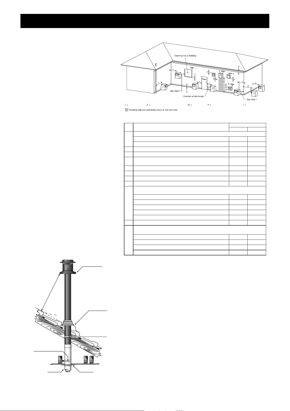
• Vertical clearances when using a roof
terminal (ESROOFCOWL) are shown in
Fig.1.
• If in doubt contact Rinnai (phone number
on the back page).
Horizontal Clearances (Extract AS/NZS 5601 Fig. 6.2)
Vertical Clearances Fig.1
Flue terminal Fan assisted flue appliance only Gas meter Electricity meter or fuse box Mechanical air inlet
Natural draft Fan assisted
•Appliances 002003tupnih/JM05otpu
•Appliances 003005tupnih/JM05revo
003003*ecafrusrehtoroynoclabaevoba,dnuorgehtmorFb
003005*renroclanretxerollawnruteratnorFc
d
From a gas meter (M) (see 5.11.5.9 for vent terminal location of regulator )
00010001)stnemeriuqerdnalaeZweNr
of6.6elbaTees(
e From an electricity meter 005005†)P(xobesufro
57051epipliosroepipniardamorFf
g Horizontally from any building structure* = or obstruction facing a terminal 500 500
h From any other flue terminal , cowl, or combustion air intake † 500 300
•Appliances 003005*tupnih/J
M051otpu
•Appliances over 150 MJ/h input up to 200 MJ/h input * 1500 300
•Appliances over 200 MJ/h input up to 250 MJ/h input * 1500 500
•Appliances 00510051*tupnih/JM052revo
• All fan-assisted flue appliances , in the direction of discharge - 1500
00010051rewolbaps
agnidulcni,telnirialacin
ahcemamorFk
051051tupnirh/JM05otpusretaehecapS•
• Other appliances 005005tupnirh/JM05otpu
•Appliances over 50 MJ/h input and up to 150 MJ/h input 1000 1000
•Appliances 00510051tupn
ih/JM051revo
1Where dimensions c, j or kcannot be achieved an equivalent horizontal distance
measured diagonally from the nearest discharge point of the terminal to the opening
may be deemed by the Technical Regulator to comply.
2See Clause 6.9.4 for restrictions on a flue terminal under a covered area.
3See Figure J3 for clearances required from a flue terminal to an LP Gas cylinder.
Aflue terminal is considered to be a source of ignition.
4
metI.feR
a
Min. clearances (mm)
Below eaves, balconies and other projections:
j
Horizontally from an openable window, door, non-mechanical air inlet, or any other opening into a building
with the exception of sub-floor ventilation:
Vertically below an openable window, non-mechanical air inlet, or any other opening into a building with the
exception of sub-floor ventilation:
NOTES:
† - Prohibited area below electricity meter or fuse box extends to ground level.
FIGURE 6.2 (in-part) MINIMUM CLEARANCES REQUIRED FOR BALANCED FLUE TERMINALS, FAN-ASSISTED FLUE
TERMINALS, ROOM-SEALED APPLIANCE TERMINALS AND OPENINGS OF OUTDOOR APPLIANCES
* - unless appliance is certified for closer installation
For appliance snot addressed above acceptance should be obtained from the Technical Regulator.
n
Minimum
Clearance
500 mm
ESROOFCOWL
Decktite or lead
collar flashing
ESPLATE
ESPIPE900
Flue pipe clip
supplied with
ESPIPE900
Flue pipe clip
supplied with
ESROOFCOWL


 User manual")