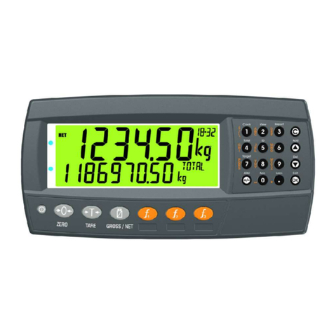
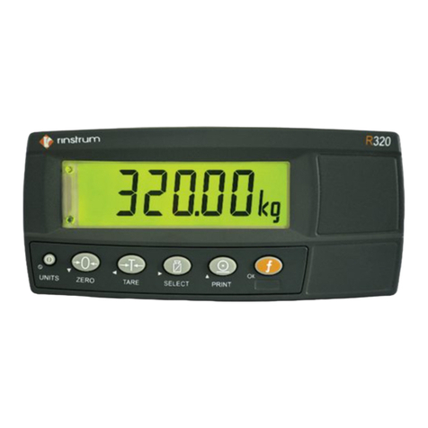
Rinstrum 2100 Instruction manual

2100
Digital Indicator
Quick StartManual
Foruse with Software Versions 2.0 and above
2100-601-250

Rinstrum -2100 Digital IndicatorQuick StartManual Rev2.50
Page 2
Copyright
All RightsReserved. Nopart of thisdocument maybe copied,
reproduced, republished, uploaded, posted, transmitted, distributed,
stored inor introduced intoaretrieval systeminanyform, or byany
means (electronic, mechanical, photocopying, recording or otherwise)
whatsoever without prior written
permission of RinstrumPtyLtd.
Disclaimer
RinstrumPtyLtdreserves the right tomake changes tothe products
contained inthismanual inorder toimprovedesign,
performance or reliability.
The information inthismanual isbelieved tobe accurateinall respects
at the timeof publication, but issubject tochange without notice.
RinstrumPtyLtdassumes no responsibilityfor anyerrors or omissions
and disclaimsresponsibilityfor anyconsequences resulting fromthe
use of the information provided herein.
SPECIALNOTE
Trade Use of the Rinstrum 2100
Thismanual mayoccasionallymake reference toTrade Use
settingsof the 2100. Onlyproperlymarked Trade Certified versions
of the 2100 can be used in LegalforTrade applications. Trade
Certification is onlyavailable on 2100 instrumentswith software
Versions2.0 and above.
Someindividual settings maynot be legal for trade use. Please check
regulations withthe appropriateWeightsand Measures Authority.
“Everything shouldbe made as simpleas possible, but not
simpler.”
- Albert Einstein-

Rinstrum -2100 Digital IndicatorQuick StartManual Rev2.50
Page 3
Tableof Contents
1. INTRODUCTION............................................................4
1.1. Approvals...............................................................4
1.2. Features.................................................................4
1.3. rin-SMARTSoftwareOptions.................................4
1.4. Manuals.................................................................4
2. SPECIFICATIONS.........................................................5
3. WARNINGS...................................................................6
3.1. General..................................................................6
3.2. DC PowerSupply...................................................6
3.3. Load Cell Signalsand Scale Build .........................6
3.4. Configuration Issues..............................................6
4. INSTALLATION.............................................................7
4.1. Special Function Key.............................................7
4.2. Electrical Safety.....................................................7
5. CONNECTIONS.............................................................8
5.1. Connecting Shields................................................8
5.2. Cable Shield Connection and Earthing ..................9
5.3. Unused Pins...........................................................9
5.4. Load Cell Connection...........................................10
6. FULL SETUP...............................................................12
7. SAFESETUP...............................................................20
8. OPERATORMENU SETUP.........................................20
9. ENABLING SOFTWAREOPTIONS............................20
10.RS-485 COMMUNICATIONS.......................................22
11.ERRORMESSAGES...................................................22
12.BATTERYOPERATION..............................................22
13.DIAGNOSTICERRORS...............................................23

Rinstrum -2100 Digital IndicatorQuick StartManual Rev2.50
Page 4
1.Introduction
Thismanualcontains information on the installation, calibration
and setup of the 2100.
1.1.Approvals
•NSCS403 approval(6000 divisions at 1µV/division).
•NMI TC6033 approval(6000 divisions at 1µV/division).
•C-tick approved and CEapproved.
1.2.Features
•27mm alphanumericLCD display(LEDback-lighting).
•Programmablespecialfunction keyand three remoteinputs.
•Full setup and calibration.
•Sixwireload cell wiring.
•Checkweighing, kg/lbswitching, totalising, intelligent
batching, counting, live weight, hold/peak holdfunctions.
•Five point linearitycorrection.
•RealTimeClock and Calendar.
•RAMforstoring Zero, Tareand Totalsettings, etc.
•Soft PowerOn/Off forinactivityautopowerdown.
1.3.rin-SMART Software Options
•0224 (SERIAL)EnableRS-232 serialcommunications
•0225 (SETP)Enablesetpoint output
1.4.Manuals
Formoreinformation on the 2100 refertothe 2100
Reference Manual and 2100 OperatorManual (available
free of charge from www.rinstrum.com).

Rinstrum -2100 Digital IndicatorQuick StartManual Rev2.50
Page 5
2.Specifications
Performance
Display Backlit alphanumericLCD withsix27mm high digits
Backlight LEDbacklight withadjustablebrightness
DisplayResolution Upto30,000 divisions, minimumof 0.25µV/division
(Trade 6000 divisionsat 1µV/division)
Count-by 1, 2, 5, 10, 20, 50, 100 (Entered inDisplayed Weight)
ZeroCancellation +/ –2.0mV/V
Span Adjustment 0.1mV/V to3.0mV/V full scale
Stability/Drift Zero: <0.1uV/°C, Span <10ppm/°C,
Linearity<20ppm, Noise<0.05µVp-p
Operating
Environment Temperature: –10 to+50°Cambient, Humidity: <90%
non-condensing
Digital
Setup and Calibration
Full digitalwithvisualprompting inplainmessages
MemoryRetention Full non-volatileoperation
DigitalFilter Averaging from1to100 consecutivereadings
ZeroRange Adjustablefrom+/–2% to+/–20% of full capacity
A/DConverter
Type 24bit SigmaDelta
Resolution
8,388,608 internalcounts
A/DSyncFilter Selectable25/30Hz, FIRfilter>80dB
LoadCells
Excitation 8 voltsforup to8x350 ohmload cells(6-wire+
shield)
Serial Comms(SoftwareOption 0224)
Serialoutput SingleRS-232 asautomatictransmit, network or
printerdrive
PowerInput
Standard General10 to15VDC (60mA to400mA depending on load cells
and backlight)
ON/OFF keywithoverride and Auto-Off software
Variants AC ACPower: 110/240VAC50/60Hz 10VA fitted ins/s
housing
DC DC Power: 12-24VDC 10VA fitted ins/shousing
BatteryRechargeable: 12VDC Batteryfitted ins/shousing
Dimensions
Bodysize 189mm (L)x99mm (H) x23mm (D)
Panelcutout Flushmounted withcableholesdrilled separately
(templateprovided)

Rinstrum -2100 Digital IndicatorQuick StartManual Rev2.50
Page 6
3.Warnings
3.1.General
•Instrument not tobe subject toshock, excessive vibration or
extremes of temperature(beforeorafterinstallation).
•Inputsareprotected against electricalinterference, but
excessive levelsof electro-magneticradiation and RFI may
affect the accuracyand stability.
•Forfull EMCorforRFI immunity, termination of the load cell
shieldat the 2100 end isimportant.
•Instrument and load cell cablearesensitive toexcessive
electricalnoise. Install well awayfromanypowerorswitching
circuits.
3.2.DC Power Supply
•DC supplyneed not be regulated provided it isfree of
excessive electricalnoise and sudden transients.
•Instrument can be operated fromhigh qualityplug-pack
provided thereissufficient capacitytodrive bothit and load
cells.
•Use plug packs witharating of 10VDC to12VDC with
current outputsof 0.5to1A.
3.3.Load Cell Signalsand ScaleBuild
•Verylowoutput scalebases can be used but mayinduce
someinstabilityinweight readings when used withhigher
resolutions (ie. higheroutput/lowernumberof divisions
equalsgreaterdisplaystability/accuracy).
3.4.Configuration Issues
•Configuration and calibration can be performed fromfront
panel, using digitalsetup. When Full Setup isused, all menu
itemsareaccessibleand caremust be taken toensureno
accidentalchanges aremade tocalibration and trade
settings.
•Enterapasscode toprevent unauthorised oraccidental
tampering.

Rinstrum -2100 Digital IndicatorQuick StartManual Rev2.50
Page 7
4.Installation
The following steps arerequired toset up the 2100 indicator.
•Inspect indicatortoensuregood condition.
•Ensuremounting options and connectorsareavailable.
•Use connection diagramstowireup load cell, powerand
auxiliarycables as required. Connectorsforall cables are
supplied withindicator.
•Instrument has built inpanelmounting screws. Use the
"PanelDrilling Template" provided forholelocations.
•Connect Powertoinstrument and press <POWER> key(if
not overridden)tostart instrument.
•Followinstructions inFull Setup section page 12 toconfigure
and calibrateinstrument.
•Enterpasscode toprotect settings fromtampering. Record
passcode forfuturereference.
•Toturninstrument OFF press and hold <POWER> keyfor
three seconds (until displayblanks).
4.1.Special Function Key
•The SpecialFunction Keyon the 2100 ships as ablank key.
If anyof the specialfunctions aretobe used on the indicator
it isimportant that the matching function keysticker
(supplied)isapplied tothe keypad.
•Ensurekeypad isclean and drybeforeaffixing sticker.
Cleaning Keypad: Wipe withasoft clothslightlydampened
witheithermethylated spiritsorwarm soapywater.
4.2.Electrical Safety
•Foryourprotection all mains electricalhardwaremust be
rated forenvironmentalconditions of use.
•Pluggableequipment must be installed nearan easily
accessiblepowersocket outlet.
•Toavoidthe possibilityof electricshock ordamage tothe
instrument, alwaysswitch off orisolatethe instrument from
the powersupplybeforemaintenance iscarried out.

Rinstrum -2100 Digital IndicatorQuick StartManual Rev2.50
Page 8
5.Connections
5.1.Connecting Shields
To obtainfull EMCorforRFI immunitywiththe2100, the
loadcell shieldMUST beconnectedelectricallytothe
metal shell oftheDB9connector. Refertodiagrams
belowortoinstructionssuppliedwiththeconnector.
Fold shield wiresback
overoutside of cable
insulation socable
clampof backshell
makesgood electrical
contact withshield
when installed.
Twist shield wires
togetherand solder
endstoDB9casing.

Rinstrum -2100 Digital IndicatorQuick StartManual Rev2.50
Page 9
5.2.CableShield Connection and Earthing
•Careshouldbe taken when connecting shields tomaximise
RFI immunityand minimise earthloops and cross-talk
(interference)between instruments.
•ForRFI immunity, termination of the load cell shieldat the
2100 end isimportant (ie. withconnection tothe 2100 case
viathe shieldconnection).
•The 2100 enclosureisdirectlyconnected tothe shield
connections on the cables.
•The 2100 shouldbe connected toearthviaasinglereliable
link toavoidearthloops.
•Whereeach instrument isseparatelyearthed,
interconnecting cableshields shouldbe connected at one
end only.
•Caution: Someload cellsconnect the cableshielddirectlyto
the load cell (and thereforethe scalebase). Connection of
the shieldinthissituation maybe sitespecific.
•The instrument complies withrelevant EMCstandards
provided case ground connection iscorrectlymade.
Resistance measured between 2100 case and nearest earth
point shouldbe less than 2ohms.
•If staticproblemsareexpected, options 0084/0085 maybe
required toprotect the serialoutputs.
5.3.Unused Pins
UnusedpinsareNOTtobeconnected.
Reason: The functions of the pins maynot be compatiblewith
equipment at the otherend (eg. connecting output pins toaPC
communications port mayaffect the operation of the PC).

Rinstrum -2100 Digital IndicatorQuick StartManual Rev2.50
Page 10
5.4.Load Cell Connection
5.4.1.6-Wire Connection
Note: Sense lines MUSTbe connected.
5.4.2.4-Wire Connection
*Formoreinformation on shielding refertopage 8.

Rinstrum -2100 Digital IndicatorQuick StartManual Rev2.50
Page 11
5.4.3.AuxiliaryConnection
*Formoreinformation on shielding refertopage 8.
Note: DoNOTconnect unused pins. Formoreinformation
refertopage 9.
RemoteDisplay
2100 Pin RemoteDisplayPlug
3(TXD) RXD/ Receive
5(GND) GND / Ground
Printer
2100 Pin PrinterPlug -DB25F
3(TXD) RXD-Pin 3
5(GND) GND -Pin 7
4(DTR) DTR-Pin 20
DirectComputer Link
2100 Pin ComputerDB-9F (DB-25F)
2(RXD) TXD-Pin 3(Pin 2)
3(TXD) RXD-Pin 2(Pin 3)
5(GND) GND -Pin 5(Pin 7)

Rinstrum -2100 Digital IndicatorQuick StartManual Rev2.50
Page 12
5.4.4.IO Connections
5.4.5.Power
Warning
For2100 use only10-15 VDC
Voltagesoutside thisrange maycause
improperoperation ordamage.
Note: Variantsof the 2100 mayrequiredifferent power
requirements. RefertoVariant DataSheet.
6.Full Setup
Full Setup provides access toconfigureand
calibratethe instrument.
•Ensureinstrument isOn. Press the <ZERO>
and <POWER> keystogetherfortwoseconds.
•Tosave settings, exit and returntonormalweighing mode,
press the <ZERO> and <POWER> keystogetherfortwo
seconds orselect -End - fromthe menus.
⊗
Indicatessetting istrade critical and calibration counter
will be incremented if setting ischanged.
®
Indicatesfunctionsareonlysuitable forremoteinputs.

Rinstrum -2100 Digital IndicatorQuick StartManual Rev2.4
Page 13
GRP
ITM
SEL
EDT
Underline=Defaults
OK
BUILD DP⊗Decimal PointPosition 000000, 00000.0, 0000.00, 000.000, 00.0000, 0.00000 Accept
CAP⊗MaximumCapacity SEL changes position, EDT changes digit. Accept
RES⊗Resolution (Count-By) 1, 2, 5, 10, 20, 50, 100 Accept
UNITS⊗Units ofMeasure none, g, kg, lb, t, oz Accept
HI.RES⊗Resolution x10 Mode OFF, ON Accept
OPTION USE⊗Industrial or TradeUse TRADE (Trade), INDUST (Industrial)(+and –weighing) Accept
FILTER Digital Filtering/Averaging 1, 2, 5, 10 , 25, 50, 75, 100 (number of readings) Accept
MOTION⊗Motion Detection Setting none, 0.5-1.0t, 1.0-1.0t, 0.5-0.5t (fine), 1.0-0.5t,
0.5-0.2t, 1.0-0.2t, 5.0-0.2t (coarse)
Default =0.5graduations per 1.0second (Time)
Accept
AUTO.Z AutoZeroon Power Up OFF, ON Accept
Z.TRAC⊗ZeroTracking Setting OFF, SLOW (0.5div/sec), MED (2 div/sec),
FAST (10 div/sec)Accept
Z.RANGE⊗ZeroKey Range –2+2, –1+3, –20+20 (% of full scale) Accept
Z.BAND⊗Zero'Dead'Band SEL changes position, EDT changes digit. Accept

Rinstrum -2100 Digital IndicatorQuick StartManual Rev2.4
Page 14
GRP
ITM
SEL
EDT
Underline=Defaults
OK
CAL ZERO⊗ZeroCalibration Routine
(Current weight displays) Removeall weight.
OK starts routine (Z.inP displays).
ITM key toexit, OK torepeat routine.
SPAN⊗SpanCalibration Routine
(Current weight displays) Add test weight.
Set correct weight.
SEL changes position, EDT changes digit.
OK starts routine (S.inP displays).
ITM key toexit, OK torepeat routine.
ED.LIN⊗EditLinearisation Points
L1. --- Select Linearisation
point 1to5(L2, L3, L4, L5).
(Approx. % of full scale)
Set capacity of test weight.
SEL changes position, EDT changes digit.
OK starts routine (L.inP displays).
ITM key toexit, OK torepeat routine.
CLR.LIN⊗Clear Linearisation Points
L1. --- Select Linearisation
point 1to5(L2, L3, L4, L5).
(Approx. % of full scale)
OK toclear point or ITM key toexit.
FAC.CAL⊗FactoryCalibration
Cont.N (No)
Cont.Y (Yes)
Cont.N
Warning: Choosing Cont.Y will restore default factory
calibration in BUILD and CAL menus.
Accept

Rinstrum -2100 Digital IndicatorQuick StartManual Rev2.4
Page 15
SPEC OP.PC Security Passcodefor
Operator Menu Setup (0000 no passcode).
Set 4digit passcode (eg. 1234).
SEL changes position, EDT changes digit.
Activated only when FULL.PC is alsoset.
Accept
FULL.PC⊗Full Security Passcodefor
Digital Setup (0000 no passcode).
Set 4digit passcode (eg. 1234).
SEL changes position, EDT changes digit.
Accept
KEY.LOC⊗
FrontPanel Key Locking
Zero, Tare, Gross/Net, Print ZTGP Letter indicates key is unlocked.
(-)Dashindicates key is locked.
SEL changes position, EDT changes digit.
Accept
KEY.FN Key Functions
Position 1: Keypad Function
Key
Positions 2, 3&4: Remote
Inputs
®Front PanelKeys:ZZero,
TTare, GGross/Net, P Print
(---- no functions assigned).
KeypadFunction Key: U lb/kgswitching, C Count,
H Hold, E Peak Hold, L LiveWeight, S ShowTotal,
B Batch, (-)Nofunction.
Remote Inputs: Z Zero, T Tare, G Gross/Net, P Print,
U lb/kgswitching, CCount, HHold, E Peak Hold,
L LiveWeight, S ShowTotal, B Batch, K Blank®,
(-)Nofunction (enableIOpinas output).
Accept
B.LIGHT BacklightOperation ON, AUTO, OFF
(Automatically turns instrument off after 10 seconds of
inactivity)
Accept
BRIGHT BacklightBrightness 01 to 10
(01=10%, 10=100%) Accept

Rinstrum -2100 Digital IndicatorQuick StartManual Rev2.4
Page 16
GRP
ITM
SEL
EDT
Underline=Defaults
OK
SPECctd.
AUT.OFF AutomaticPower Off NEVER, 20 S, 30 S, 60 S, 300 S, 600 S
(Seconds of inactivity before power down) Accept
AUX.DSP AuxiliaryDisplay (Time)
(Recommended for batching
Operations)
OFF, TIMEAccept
SYNC⊗A/DFrequency 25Hz or 30Hz (This setting may affect calibration.) Accept
SERIAL TYPE Serial OutputType OFF, NET, AUTO, PRINT, MASTER Accept
ADDR Serial Address 00 to 31 (Default = 01)
SEL changes position, EDT changes digit. Accept
BAUD Serial Baud Rate 1200, 2400, 4800, 9600, 19200 Accept
BITS Serial Format Options
Position 1: Parity
Position 2: DataBits
Position 3: Stop Bits
Position 4: DTR Handshake
N81- (Default SerialFormat Options)
SEL changes position, EDT changes digit.
Parity: NNone, OOdd, EEven
Data Bits: 7or 8databits
Stop Bits: 1or 2stop bits
DTR: (-)DTR disabled or dDTR enabled
Accept
PRN.ID PrintoutID OFF, ON (Adds ADDR IDtoprintouts) Accept

Rinstrum -2100 Digital IndicatorQuick StartManual Rev2.4
Page 17
SERIAL
ctd.
PRN.ROW
RowPadding on Printout
00.0
to10.10
00.00 Number of line feeds toadd before printout.
00.00 Number of line feeds toadd after printout. If
padding is set to10 then aformfeed character is sent.
Accept
PRN.COL
ColumnPadding on Printout
00
to
20
(Number of spaces toadd at start of eachline of
printout.)
Accept
SET.PTS
OPTN A
-
G
O
H
-
-
GOH
-
(Default Setpoint Settings
)
Accept
-
none
-
None disables the setpoint when not inuse
A
ctive
A
Activefor levelcontroland overload alarms
S
low
S
Slow
Fill
used inconjunction withFast Fill
G
ross
G
Gross (usegross weight)
N
et
N
Net (usenet weight, Tare
s before operating relay)
R
eading
R
Reading (usecurrent displayed weight)
H
eld
H
Held(useHeldreading)
O
ver
O
Over (weight increasing)
U
nder
U
Under (weight decreasing, negativeweighing)
H
igh
H
High (ActiveHigh logic)
L
ow
L
Low(ActiveLowlogic)
-
none
-
None (no internalbeep during relay operation)
S
ingle
S
Single(one internalbeep during operation)
D
ouble
D
Double(doubleinternalbeeps during operation)
F
lash
F
Flash(Displa
y flashes)
TARGA
Target A
(Primary target inbatching)
SEL
changes position,
EDT
changes digit.
Accept

Rinstrum -2100 Digital IndicatorQuick StartManual Rev2.4
Page 18
GRP
ITM
SEL
EDT
Underline=Defaults
OK
SET.PTS
ctd.
OPTN B
-
G
O
H
-
-none Gross Over High -none
Active Net Under Low Single
Fast Reading Double
H
eld
F
lash
-
GOH
-
(Default)
Same as OPTN Aexcept:
FFast Fill used inconjunction withSlowFill.
Accept
TARGB
Target B
(Preliminary value inbatching)
SEL
changes position,
EDT
changes digit.
Accept
OPTN C
-
G
O
H
-
-none Gross Over High -none
Active Net Under Low Single
Dump Reading Double
Pass HeldFlash
-
GOH
-
(Default)
Same as OPTN Aexcept:
DDumpsignalfor weight toreturn tozero or dump
time(refer toD.TIMEbelow).
PPass output for setpoint 3only.
(checkweigh appl
ication)
Accept
TARGC
Target C
(Not used inbatching)
SEL
changes position,
EDT
changes digit.
Accept
FLIGHT
In
-
Flight
SEL
changes position,
EDT
changes digit.
Accept
HYS
Hysteresis
SEL
changes position,
EDT
changes digit.
Accept
D.TIME
DumpTime
00.0
to
20.0
seconds
0for dumptozero weight, otherwiseoperated for
the timespecified.
Accept

Rinstrum -2100 Digital IndicatorQuick StartManual Rev2.4
Page 19
CLOCK
TIME TimeSetting 24 hour clock
HH.MM.SS displays Set timeinthe format HH.MM
SEL changes position, EDT changes digit. Accept
DATE Date Setting
DD.MM.YY displays Set day and monthinthe format DD.MM
Set the year inthe format YYYY Accept
Accept
QA.OPT⊗Quality Assurance Reminder OFF, ON (Flashes QA Due on due date) Accept
QA.DATE⊗Quality Assurance DueDate Set day and monthinthe format DD.MM
Set the year inthe format YYYY Accept
Accept
TEST SCALE LoadCell Test
Displays load cell output inmV/V(Format=0.0000)
Trade Mode=5sec display
FRC.OUT Force Outputs --- (Default display)
EDT advances through eachoutput (1--, -2-, --3)
TST.INP Test Inputs --- (Default display)
EDT advances through eachinput (1--, -2-, --3)
FACTRYDEFLT RestoreFactoryDefaults
Cont.N (No)
Cont.Y (Yes)
Cont.N
Warning: Choosing Cont.Y will clear all stored
dataexcept calibration.
Accept
CONFIG ConfigureSoftwareOptions Used toenter licensecodes for software options. Accept
-END - EXITSETUP
Acceptsettingsand returnto
normal weighing mode Accept

Rinstrum- 2100 Digital Indicator Quick Start Manual Rev2.4
Page 20
7.SafeSetup
SafeSetup providesaccess toconfigurethe
instrument without access totrade or
calibration specificitems.
•Ensureinstrument isOn. Press the <GROSS/NET> and
<POWER> keystogetherfortwoseconds.
•Tosavesettings, exit and returntonormal weighing
mode, press the <GROSS/NET> and <POWER> keys
togetherfortwosecondsorselect -End - fromthe
menus.
8.Operator Menu Setup
The OperatorMenu providesaccess tosetpoint
target and flight settings.
•Ensureinstrument isOn. Press the <TARE>
keyfortwoseconds.
•Tosavesettings, exit and returntonormal weighing
mode, press the <TARE> keyfortwosecondsorselect
-End - fromthe menus.
9.Enabling Software Options
Toenable anyof the rin-Smart Softwareoptionsalicense
code must be entered. The licensecodesareunique to
eachoption and toeachinstrument. Theseoptionsmaybe
factoryinstalled orinstalled in the field.
Followthe stepsbelowtodiscoverwhichoptionsare
installed ortoinstall anotheroption:
•Ensure the instrument is On.
•Press the <POWER> and
<FUNCTION> keys togetherfortwo
seconds.
Other manuals for 2100
1
Table of contents
Other Rinstrum Measuring Instrument manuals
Rinstrum
Rinstrum 5200 Use and care manual

Rinstrum
Rinstrum K405 User manual

Rinstrum
Rinstrum 400 Series User manual

Rinstrum
Rinstrum 400 Series Instruction manual

Rinstrum
Rinstrum R300 Series Instruction manual

Rinstrum
Rinstrum 5200 Instruction manual

Rinstrum
Rinstrum 400 Series User manual
Rinstrum
Rinstrum R300 Series User manual

Rinstrum
Rinstrum 400 Series Instruction manual
Rinstrum
Rinstrum M4202 User manual